EP0918436B1 - Umwandlung von ins Zeilensprung-System dekodiertem Video in Vollbild-Video unter Berücksichtigung des Abtastsystems vor Kodierung - Google Patents
Umwandlung von ins Zeilensprung-System dekodiertem Video in Vollbild-Video unter Berücksichtigung des Abtastsystems vor Kodierung Download PDFInfo
- Publication number
- EP0918436B1 EP0918436B1 EP19980121030 EP98121030A EP0918436B1 EP 0918436 B1 EP0918436 B1 EP 0918436B1 EP 19980121030 EP19980121030 EP 19980121030 EP 98121030 A EP98121030 A EP 98121030A EP 0918436 B1 EP0918436 B1 EP 0918436B1
- Authority
- EP
- European Patent Office
- Prior art keywords
- image data
- line
- scanning system
- signal
- output
- Prior art date
- Legal status (The legal status is an assumption and is not a legal conclusion. Google has not performed a legal analysis and makes no representation as to the accuracy of the status listed.)
- Expired - Lifetime
Links
- 230000000750 progressive effect Effects 0.000 title claims description 60
- 238000006243 chemical reaction Methods 0.000 title description 13
- 230000015654 memory Effects 0.000 claims description 49
- 230000004044 response Effects 0.000 claims description 18
- 238000000034 method Methods 0.000 claims description 16
- 230000002401 inhibitory effect Effects 0.000 claims 3
- 230000002596 correlated effect Effects 0.000 claims 2
- 230000033001 locomotion Effects 0.000 description 29
- 238000010586 diagram Methods 0.000 description 13
- 230000005540 biological transmission Effects 0.000 description 5
- 230000006870 function Effects 0.000 description 4
- 230000001934 delay Effects 0.000 description 3
- 230000003111 delayed effect Effects 0.000 description 3
- 238000004891 communication Methods 0.000 description 2
- 230000008054 signal transmission Effects 0.000 description 2
- 230000001419 dependent effect Effects 0.000 description 1
- 238000001514 detection method Methods 0.000 description 1
- 238000003672 processing method Methods 0.000 description 1
- 238000005070 sampling Methods 0.000 description 1
Images


Classifications
-
- H—ELECTRICITY
- H04—ELECTRIC COMMUNICATION TECHNIQUE
- H04N—PICTORIAL COMMUNICATION, e.g. TELEVISION
- H04N7/00—Television systems
- H04N7/01—Conversion of standards, e.g. involving analogue television standards or digital television standards processed at pixel level
- H04N7/0117—Conversion of standards, e.g. involving analogue television standards or digital television standards processed at pixel level involving conversion of the spatial resolution of the incoming video signal
- H04N7/012—Conversion between an interlaced and a progressive signal
-
- H—ELECTRICITY
- H04—ELECTRIC COMMUNICATION TECHNIQUE
- H04N—PICTORIAL COMMUNICATION, e.g. TELEVISION
- H04N19/00—Methods or arrangements for coding, decoding, compressing or decompressing digital video signals
- H04N19/10—Methods or arrangements for coding, decoding, compressing or decompressing digital video signals using adaptive coding
- H04N19/134—Methods or arrangements for coding, decoding, compressing or decompressing digital video signals using adaptive coding characterised by the element, parameter or criterion affecting or controlling the adaptive coding
- H04N19/157—Assigned coding mode, i.e. the coding mode being predefined or preselected to be further used for selection of another element or parameter
- H04N19/16—Assigned coding mode, i.e. the coding mode being predefined or preselected to be further used for selection of another element or parameter for a given display mode, e.g. for interlaced or progressive display mode
-
- H—ELECTRICITY
- H04—ELECTRIC COMMUNICATION TECHNIQUE
- H04N—PICTORIAL COMMUNICATION, e.g. TELEVISION
- H04N19/00—Methods or arrangements for coding, decoding, compressing or decompressing digital video signals
- H04N19/44—Decoders specially adapted therefor, e.g. video decoders which are asymmetric with respect to the encoder
-
- H—ELECTRICITY
- H04—ELECTRIC COMMUNICATION TECHNIQUE
- H04N—PICTORIAL COMMUNICATION, e.g. TELEVISION
- H04N19/00—Methods or arrangements for coding, decoding, compressing or decompressing digital video signals
- H04N19/85—Methods or arrangements for coding, decoding, compressing or decompressing digital video signals using pre-processing or post-processing specially adapted for video compression
Definitions
- the present invention relates to a scanning system converting apparatus and a method for the same, and more particularly to the technique in which a scanning system is converted from an interlace scanning system into a progressive scanning system when an image data which is coded by a coding system such as the MPEG2 (Moving Picture Expert Group 2) is decoded.
- a coding system such as the MPEG2 (Moving Picture Expert Group 2)
- image data which can be coded in accordance with MPEG2 there are image data which are coded by an interlace scanning system which is used in monitors such as an NTSC TV monitor and image data which are coded by a progressive scanning system which is used in monitors such as a monitor of a personal computer.
- image data coded in accordance with the MPEG2 are received through a communication line, decoded image data must be outputted to the NTSC TV monitor in the interlace scanning system.
- the image data is outputted in the interlace scanning system and, at the same time, is outputted to a monitor of the progressive scanning system such as the monitor of the personal computer.
- a scanning system converting apparatus it is necessary for a scanning system converting apparatus to convert the scanning system of the image data outputted from the interlace scanning system into the progressive scanning system.
- the sampling position of the image data is shifted between a previous field and the current field in a vertical direction, as shown in relation of frame period and vertical axis of Fig. 1 .
- there is a method of calculating a difference between a signal interpolated from the upper line and the lower line and a signal in the previous field as shown in Fig. 1 .
- this method there is a case where the signal which is obtained by the interpolation greatly differs from an actual signal in the region with a high vertical resolution.
- JP-A-9-182111 a video signal processing method is described in Japanese Laid Open Patent Application ( JP-A-9-182111 ).
- an interlace component signal of 270 MHz in a (4: 2: 2) signal format is inputted to the video processing circuit from an input terminal 1, and converted into a 10-bit signal of 27 MHz in parallel in the processing circuit.
- first and second blocks of a progressive component signal are inputted from the input terminals 1 and 2.
- An interpolating operation is performed to the color components of the first and second signal blocks so as to generate a serial signal of 360 MHz in a (4: 2: 2: 4) signal format.
- the serial signal is converted into a 10-bit parallel signal of 36 MHz.
- these component signals are re-converted into the signal formats in the input.
- a video display system is described in Japanese Laid Open Patent Application ( JP-A-8-251504 , also published under EP-A-0714203 ).
- a video signal is received in a switch 106.
- a user can select, by the switch 106, at least one of auxiliary channel by which a main channel image and a special function image can be viewed, when he does not want to view the main channel image for the special function image.
- a main video channel data is converted in scanning system from an interlace scanning system into a progressive scanning system by a scanning system converter 216.
- a logic unit 212 processes an auxiliary channel data to format into a selected special function. The data is inputted into the scanning converter 216 and the special function image is displayed at a proper position to the main channel image.
- the TV signal transmission apparatus is composed of a first motion detecting section for detecting a motion in a frame of an image data of a progressive scanning system and a second motion detecting section for detecting a motion between frames of an image data of an interlace scanning system.
- a fixed value is added to a transmission signal so that the motion can be detected based on the fixed value.
- an automatic scanning format converter with seamless switching is disclosed. More specifically, an apparatus which converts different scanning formats of different sources and can switch seamless between different formats, e.g. interlace and progressive format is disclosed. Therefore, different conversion paths, namely a P-I conversion path and an I-P conversion path are provided. In the P-I and I-P conversion paths different signal processing delays occur which are compensated by a frame memory (delay) network. This allows seamless switching between, for example, a television commercial in the progressive scan format and a television main program material in interlace scan format.
- US-A-5 444 491 discloses a television receiver for receiving and decoding a transmitted television signal.
- the television signal comprises image frames encoded in different transmission formats, which may include progressive scanning formats. These formats are selected from a set of transmission formats and differ from each other in non-program-content characteristics, such as spatial-resolution and frame-rate.
- the television receiver comprises means for receiving this format identification information and means for decoding the encoded image frames using the format identification information.
- the television receiver additionally may include transmission format means for using the decoded identification information to transform the format, e.g. an interlaced format, of the received image frames from transmission format to the display format, e.g. progressive format.
- JP-A-09 182 032 , EP-A-0 757 482 , EP-A-0 710 018 an US-A-5 365 273 disclose further alternatives of scanning format conversion.
- an object of the present invention is to provide a scanning system converting apparatus and a method for the same, in which the image quality of an image after conversion is not degraded, compared with the image quality of an original image, when a scanning system of an image data is converted from an interlace scanning system into a progressive scanning system.
- a scanning system converting system for a display unit of a progressive scanning system according to claim 1.
- the coded image data is desirably obtained by coding the first image data based on a MPEG2, and a decoder desirably decodes the coded image data based on the MPEG2.
- original image data may be obtained by coding an image data based on a MPEG2, and a decoding step may include decoding the coded image data based on the MPEG2.
- Fig. 3 is a block diagram which shows the structure of the scanning system converting apparatus according to the first embodiment of this embodiment.
- the image output system is composed of an MPEG2 decoder 1, an NTSC encoder 2, a scanning system converting circuit 3, a transfer control section 4 and a graphic system 5.
- the scanning system converting circuit 3 is composed of a field memory 3a, an average value interpolating section 3b, a line memory 3c, a motion detecting section 3d, a field correlation determining section 3e, a timing signal generating section 3f, a switch 3g, FIFO memories 3h and 3i and a switch 3j.
- the MPEG2 decoder 1 decodes an MPEG2 coded image data which has been coded in accordance with the MPEG2 and which is supplied through a communication line. Then, the MPEG2 decoder 1 outputs the decoded image data in the field frequency of the NTSC video signal of the (2:1) interlace scanning system. Also, the MPEG2 decoder 1 outputs a sync signal of the NTSC video signal.
- the MPEG2 coded image data which is supplied to the MPEG2 decoder 1 is obtained by coding an image data of the interlace scanning system or an image data of the progressive scanning system. Therefore, in order to distinguish the scanning system of the image data, a signal, Progressive_sequence, is provided in a sequence extension of a sequence header in the MPEG2 coded image data. This signal is "1" when the image data of the progressive scanning system is coded into the MPEG2 coded image data, and is "0" when the image data of the interlace scanning system is coded.
- the image data of the progressive scanning system includes the image data of a movie film.
- the frame rate of the image data is 24 Hz and is different from 30 Hz of NTSC.
- a signal, repeat_first_field is provided in the picture coding extension of the image header. When this signal is "1", the frame is repeatedly outputted so that the frame rate can be converted.
- the MPEG2 decoder 1 can recognize a field having correlation in accordance with these two kinds of signals, and generates and supplies a 2-bit field correlation signal to the field correlation determining section 3e.
- the field correlation signal has the following meaning to each value. That is,
- the NTSC encoder 2 generates an NTSC video signal based on the decoded image data and the sync signal which are outputted from the MPEG2 decoder 1.
- the generated NTSC video signal is supplied to an NTSC TV monitor (not shown) so that a corresponding image is displayed on the NTSC TV monitor.
- the scanning system converting circuit 3 converts the decoded image data which is outputted in the interlace scanning system from the MPEG2 decoder 1, into the progressive scanning system and supplies it to the transfer control section 4.
- the structure of the scanning system converting circuit 3 will be described in detail.
- the field memory 3a delays the decoded image data which is outputted from the MPEG2 decoder 1 and whose original image data is of the interlace scanning system, for one field timing and outputs to the motion detecting section 3d and the switch 3g.
- the line memory 3c delays the decoded image data which is outputted from MPEG2 decoder 1, for one line timing of the NTSC interlace scanning system and outputs to the average value interpolating section 3b.
- 1 line is composed of 720 pixels
- 1 field is composed of 240 lines
- 1 frame is composed of 2 fields, i.e., 480 lines.
- the average value interpolating section 3b calculates an average value of a twice previous field of the image data which is outputted from the MPEG2 decoder 1 and a current field of the image data which is outputted from the line memory 3c for every pixel, and outputs the average value to the motion detecting section 3d and the switch 3g.
- the motion detecting section 3d operates in accordance with an instruction from the field correlation determining section 3e.
- the motion detecting section 3d issues an instruction to the switch 3g such that the switch 3g selects the image data outputted from the field memory 3a.
- the motion detecting section 3d determines whether a difference between the image data which is outputted from the field memory 3a and the image data which is outputted from the average value interpolating section 3b is equal to or larger than a predetermined value.
- the motion detecting section 3d issues an instruction to the switch 3g such that the switch 3g selects the image data outputted from the average value interpolating section 3b, when the difference is equal to or larger than the predetermined value, and such that the switch 3g selects the image data outputted from the field memory 3a when the difference is smaller than the predetermined value.
- the field correlation determining section 3e determines the field correlation signal outputted from the MPEG2 decoder 1.
- the field correlation determining section 3e issues an instruction to the motion detecting section 3d such that the switch 3g always outputs the image data which is outputted from the field memory 3a, when the field correlation is effective (when the field correlation signal is "01", "10" or "11").
- the field correlation determining section 3e issues an instruction to the timing signal generating section 3f such that the transfer control section 4 transfers, to the graphic system 5, only an effective portion of the image data which has been converted into the progressive scanning system, e.g., only the effective portion of the first one of fields of the frame of the image data.
- the field correlation determining section 3e When the field correlation is invalid (when the field correlation signal is "00"), the field correlation determining section 3e does not issue any instruction to the motion detecting section 3d. Also, the field correlation determining section 3e issues an instruction to the timing signal generating section 3f such that the timing signal generating section 3f outputs an instruction to the transfer control section 4 so that the transfer control section 4 transfers all of the image data which has been converted into the progressive scanning system, to the graphic system. That is, the instruction is effective for the effective portion of each field of the frame of the image data.
- the timing signal generating section 3f sends a timing signal to the switch 3j in accordance with the determining result by the field correlation determining section 3e and the sync signal which is outputted from the MPEG2 decoder 1 such that the switch 3j is always switched for every line.
- the switch 3j alternately selects and outputs one of the image data which is outputted from the FIFO memory 3h and the image data which is outputted from the FIFO memory 3i based on this timing signal. Also, the timing signal generating section 3f sends to the transfer control section 4a a timing signal (hereinafter, to be referred to as an effective signal) indicating that the image data which is outputted from the switch 3j is effective, when the timing signal is in the high level.
- an effective signal a timing signal
- the switch 3g selects and outputs one of the image data which is outputted from the field memory 3a and the image data which is outputted from the average value interpolating section 3b for every line or every pixel in accordance with the instruction from the motion detecting section 3d.
- Each of the FIFO memories 3h and 3i is composed of the First-In First-Out memory which has a memory capacity of at least one line.
- One of the output signal of the field memory 3a and the output signal of the average value interpolating section 3b which is selectively outputted by the switching of the switch 3g is written in the FIFO memory 3h.
- the decoded image data which is outputted from the MPEG2 decoder 1 is written in the FIFO memory 3i.
- the transfer control section 4 has a buffer memory which stores the image data outputted from the switch 3j temporarily. Also, the transfer control section 4 supplies the effective portion of the image data which has been stored in the buffer memory to the graphic system 5 at the frame rate of 60 frames per one second, based on the signal which indicates the effective portion which is supplied from the timing signal generating section 3f.
- the graphic system 5 has a frame memory for storing the effective portion of the image data which has been transferred from the transfer control section 4. Also, the graphic system 5 displays an image on the monitor in the progressive scanning system. In this case, the graphic system displays the image data which is transferred from the transfer control section 4. However, when no image data is transferred from the transfer control section 4, the graphic system 5 displays the previous field or frame of the image data.
- scanning system converting circuit 3 In the scanning system converting apparatus of this embodiment, an operation in the case where the decoded image data is converted by the scanning system converting circuit 3 will be described.
- the operation of scanning system converting circuit 3 is different depending upon whether the MPEG2 coded image data is obtained by coding the image data of the progressive scanning system or by coding from the image data of the interlace scanning system.
- an operation in each case will be described.
- the MPEG2 decoder 1 receives the MPEG2 coded image data having Progressive_Sequence of "1". Therefore, the MPEG2 decoder 1 decodes the received MPEG2 coded image data to sequentially output as the image data of the interlace scanning system. At the same time, the MPEG2 decoder 1 supplies a sync signal to the timing signal generating section 3f, and supplies, to the field correlation determining section 3e, the field correlation signal which takes either of "01", "10” or "11” value in accordance with the field.
- An instruction is sent from the field correlation determining section 3e to the motion detecting section 3d in response to such a value of the field correlation signal with such that the switch 3g selects the image data outputted from the field memory 3a.
- the operation of the motion detecting section 3d is stopped and the switch 3g is switched to always output the image data which has been outputted from the field memory 3a.
- the image data which is outputted from the field memory 3a is delayed for one field time from the image data which has been outputted from the MPEG2 decoder 1. That is, when the image data for the first field of one frame is outputted from the field memory 3a and is written in the FIFO memory 3h, the image data for the following field is outputted from the MPEG2 decoder 1 and is written in the FIFO memory 3i.
- the timing signal to switch the switch 3j is supplied from the timing signal generating section 3f based on the sync signal which has been supplied from the MPEG2 decoder 1.
- the switch 3j is switched in response to the timing signal such that the image data outputted from the FIFO memory 3h and the image data outputted from the FIFO memory 3i are alternately outputted for every line.
- the image data which is outputted from the switch 3j is the image data of the progressive scanning system having no skip of any line.
- the image data of this progressive scanning system is supplied to the transfer control section 4 and is temporarily stored in a buffer memory of the transfer control section 4.
- the field correlation determining section 3e when it is determined that the field correlation signal value is "10", an instruction is sent to the timing signal generating section 3f so as to send an effective indication signal with the high level to the transfer control section 4. As shown in Figs. 4A and 4B , based on this instruction, the effective indication signal with the high level is sent from the timing signal generating section 3f to the transfer control section 4.
- the transfer control section 4 transfers the effective portion of the image data which is stored newly in the buffer memory to the graphic system 5. Thus, the image data which has been transferred from the transfer control section 4 is displayed on the monitor of the graphic system 5.
- the field correlation determining section 3e when it is determined that the field correlation signal value is "01" or "11", an instruction is not sent to the timing signal generating section 3f. Therefore, as shown in Figs. 4A and 4B , the effective indication signal which is sent from the timing signal generating section 3f to the transfer control section 4 becomes the low level, so that the transfer control section 4 does not transfer image data to the graphic system 5. As a result, in the graphic system 5, the image data which has been transferred last is displayed, i.e., the same image is repetitively displayed.
- Fig. 5 The timings from the decoding of the MPEG2 coded image data to the display which are described above are shown in Fig. 5 , taking as an example the case that the image data before coding is the movie film which has the frame rate of 24 Hz.
- image data of the progressive scanning system is obtained from one field of the movie film with the frame rate of 24 Hz through the scanning system conversion.
- the image data is supplied to the graphic system 5 with the frame rate 75 Hz. Therefore, the same image data is repetitively displayed to eliminate the frame rate difference.
- the MPEG2 decoder 1 receives the MPEG2 coded image data with Progressive_Sequence of "1". At that time, the MPEG2 decoder 1 decodes the received MPEG2 coded image data to sequentially output in the interlace scanning system. Also, the MPEG2 decoder 1 supplies the sync signal to the timing signal generating section 3f, and supplies the field correlation signal of the value of "00" to the field correlation determining section 3e.
- the image data which has been outputted from the MPEG2 decoder 1 is delayed for one line time and outputted to the average value interpolating section 3b.
- An average of the image data which is outputted from the line memory 3c and the image data which is outputted from the MPEG2 decoder 1 is calculated by the average value interpolating section 3b, and a signal is generated which interpolates the line which is skipped in the interlace scanning system.
- the motion detecting section 3d compares the image data which is outputted from the field memory 3a and the image data which is outputted from the average value interpolating section 3b, in response to the instruction. As to the comparing result, when it is determined that a difference between both of the image data is smaller than a predetermined value, that is, when it is determined that there is no movement between images, the motion detecting section 3d outputs an instruction to the switch 3g.
- the switch 3g is switched in response to the instruction from the motion detecting section 3d in such a manner that the image data outputted from the field memory 3a is selected.
- the motion detecting section 3d outputs an instruction to the switch 3g.
- the switch 3g is switched in response to the instruction from the motion detecting section 3d in such a manner that the average of the image data outputted from the average value interpolating section 3b is selected.
- the selected image data is written in the FIFO memory 3h.
- the writing of the image data which is outputted from the MPEG2 decoder 1 in the FIFO memory 3i, the generation of the timing signal by the timing signal generating section 3f, the switching by the switch 3j, the writing of the image data which is outputted from the switch 3j into the buffer memory of the transfer control section 4 are the same as those in the case that the image data before coding is the image data of the progressive scanning system.
- an instruction is sent to the timing signal generating section 3f such that the effective indication signal with the high level is sent to the transfer control section 4.
- the effective indication signal with the high level is sent from the timing signal generating section 3f to the transfer control section 4.
- the transfer control section 4 transfers to the graphic system 5, the effective portion of the image data which is stored newly in the buffer memory therein. Then, the image data which is transferred from the transfer control section 4 is displayed on the monitor of the graphic system 5.
- Fig. 7 The timings from the decoding of the MPEG2 coded image data to the display on the graphic system which are described above are shown in Fig. 7 , taking as an example the case that the image data before coding is the NTSC video signal which has the frame rate of 30 Hz.
- the image data before coding is the NTSC video signal which has the frame rate of 30 Hz.
- each field of each frame of the image data of the progressive scanning system after the scanning system conversion is transferred to the graphic system 5.
- the same image are repetitively displayed sometimes to cancel the difference.
- the image data which is outputted from the switch 3j and which is converted into the progressive scanning system is substantively the same as the image data before coding, so that the image quality is not degraded.
- the image data of the progressive scanning system which is outputted from the switch 3j is the same as the image data before coding in the frame rate, and a data amount of the image data which is transferred from the transfer control section 4 is a few.
- the image data which is outputted from the MPEG2 decoder 1 is of the NTSC interlace scanning system, the image data is possible to be displayed on the NTSC TV monitor and on the monitor of the graphic system through the scanning system converting circuit 3 and the transfer control section 4.
- the MPEG2 decoder 1 outputs the image data of the NTSC 2:1 interlace scanning system.
- n:1 (n is an integer equal to or more than 3) interlace scanning system.
- a plurality of field memories which have the delayed field times different from each other are provided and the FIFO memories which correspond to the plurality of field memories are provided.
- the average value interpolating section 3b is sufficient to calculate an average weighted in accordance with the vertical distance determined in order of the fields.
- the decoded data and the field correlation signal are outputted onto the different signal lines from the MPEG2 decoder 1.
- they may be outputted on the identical signal line in a time division multiplexing manner.
- the image data which is coded in accordance with MPEG2 is described as the example.
- the present invention is not limited to this.
- the present invention is possible to be applied to all cases in which when the image data of the interlace scanning system or of the progressive scanning system has been coded by a coding system other than MPEG2 and is decoded and outputted in the interlace scanning system, the image data is converted into the progressive scanning system.
- the image data after the scan conversion is substantively the same as the image data before coding so that the image quality is not degraded.
Landscapes
- Engineering & Computer Science (AREA)
- Multimedia (AREA)
- Signal Processing (AREA)
- Computer Graphics (AREA)
- Television Systems (AREA)
- Compression Or Coding Systems Of Tv Signals (AREA)
Claims (6)
- Abtastsystem-Konvertierungsvorrichtung für eine Displayeinheit eines Vollbild-Abtastsystems (Progressive Scanning System), mit:a) einer Decodiereinrichtung (1) zum Decodieren codierter erster Bilddaten in decodierte erste Bilddaten in einem Zeilensprung-Abtastsystem (Interlaced Scanning System) und zum Ausgeben von Steuerdaten, wobei die codierten ersten Bilddaten durch Codieren von Bilddaten eines Zeilensprung- oder eines Vollbild-Abtastsystems erhalten werden, und wobei die Steuerdaten anzeigen, ob das Abtastsystem der codierten ersten Bilddaten das Vollbild-Abtastsystem oder das zeilensprung-Abtastsystem ist, und ob Felder der ersten Bilddaten korreliert sind;b) einer Steuereinrichtung (3e, 3f) zum Erzeugen eines effektiven Anzeigesignals und eines ersten und eines zweiten Steuersignals basierend auf den von der Decodiereinrichtung zugeführten Steuerdaten;c) einer Feldspeichereinrichtung (3a) zum Speichern eines aktuellen Feldes der von der Decodiereinrichtung (1) ausgegebenen decodierten ersten Bilddaten und zum Ausgeben eines vorangehenden Feldes der decodierten Bilddaten für jede Zeile mit einer Verzögerung von einer Feldzeit als erste Zeilenbilddaten;d) einer ersten Zeilenspeichereinrichtung (3c) zum Speichern einer aktuellen Zeile eines aktuellen Feldes der von der Decodiereinrichtung (1) ausgegebenen decodierten ersten Bilddaten für jede Zeile und zum Ausgeben der gespeicherten vorangehenden Zeile des aktuellen Feldes für jede Zeile als zweite Zeilenbilddaten;e) einer Interpolationseinrichtung (3b) zum Erzeugen interpolierter Bilddaten für jede Zeile von der aktuellen Zeile des aktuellen Feldes und den von der ersten zeilenspeichereinrichtung (3c) ausgegebenen zweiten Zeilenbilddaten, um dritte Zeilenbilddaten auszugeben;f) einer ersten Schalteinrichtung (3g) zum Auswählen der ersten Zeilenbilddaten oder der dritten Zeilenbilddaten in Antwort auf ein erstes Schaltsignal, um die ausgewählten Bilddaten als vierte Zeilenbilddaten auszugeben;g) einer Erfassungseinrichtung (3d) zum Erfassen einer Differenz zwischen den ersten Zeilenbilddaten und den dritten Zeilenbilddaten zum Ausgeben des ersten Schaltsignals an die erste Schalteinrichtung (3g) in Antwort auf das erste Steuersignal und basierend auf dem Erfassungsergebnis, wobei, wenn die ersten Bilddaten Daten eines Vollbild-Abtastsystems sind, das erste Schaltsignal die erste Schalteinrichtung (3g) in Antwort auf das erste Steuersignal veranlasst, die ersten Zeilenbilddaten auszuwählen, und wobei, wenn die ersten Bilddaten Daten eines zeilensprung-Abtastsystems sind, das erste Schaltsignal die erste Schalteinrichtung (3g) basierend auf dem Erfassungsergebnis in Antwort auf das erste Steuersignal veranlasst, die ersten Zeilenbilddaten auszuwählen, wenn die Differenz kleiner ist als ein vorgegebener Wert, und andernfalls die dritten Zeilenbilddaten auszuwählen;h) einer zweiten Zeilenspeichereinrichtung (3h) zum Speichern der vierten Zeilenbilddaten und zum Ausgeben der gespeicherten vorangehenden Zeile der vierten Zeilenbilddaten als fünfte Zeilenbilddaten;i) einer dritten Zeilenspeichereinrichtung (3i) zum Speichern der aktuellen Zeile des von der Decodiereinrichtung (1) ausgegebenen aktuellen Feldes für jede Zeile und zum Ausgeben der gespeicherten vorangehenden Zeile des aktuellen Feldes als sechste Zeilenbilddaten;j) einer zweiten Schalteinrichtung (3j) zum abwechselnden Auswählen der fünften Zeilenbilddaten oder der sechsten Zeilenbilddaten in Antwort auf das zweite Steuersignal als ein zweites Schaltsignal, um die ausgewählten Bilddaten als Ausgangsbilddaten auszugeben; undk) einer Übertragungseinrichtung (4) mit einem Puffer zum zwischenspeichern der Ausgangsbilddaten und zum Übertragen der Ausgangsbilddaten vom Puffer zur Displayeinheit in Antwort auf einen aktiven Zustand des effektiven Anzeigesignals; wobei(l) die Steuereinrichtung (3e, 3f) das effektive Anzeigesignal derart ausgibt, dass das effektive Anzeigesignal aktiv ist, wenn die ersten Bilddaten Daten des zeilensprung-Abtastsystems sind, und derart, dass das effektive Anzeigesignal nur für das erste der Felder eines Rahmens der Ausgangsbilddaten aktiv ist, die durch den Puffer von der zweiten Schalteinrichtung empfangen werden, wenn die ersten Bilddaten Daten des Vollbild-Abtastsystems sind.
- Abtastsystem-konvertierungsvorrichtung nach Anspruch 1, wobei die codierten Bilddaten durch Codieren der ersten Bilddaten basierend auf einem MPEG2-Standard erhalten werden und die Decodiereinrichtung (1) die codierten Bilddaten basierend auf dem MPEG2-Standard decodiert.
- Verfahren zum Konvertieren eines Abtastsystems (3) eines Bilddatensignals in ein Vollbild-Abtastsystem einer Displayeinheit, mit den Schritten:a) Decodieren codierter erster Bilddaten in decodierte erste Bilddaten in einem Zeilensprung-Abtastsystem und Ausgeben von Steuerdaten, wobei die codierten ersten Bilddaten durch Codieren von Bilddaten eines Zeilensprung- oder eines Vollbild-Abtastsystems erhalten werden, und wobei die Steuerdaten anzeigen, ob das Abtastsystem der codierten ersten Bilddaten das Vollbild-Abtastsystem oder das Zeilensprung-Abtastsystem ist, und ob Felder der ersten Bilddaten korreliert sind;b) Erzeugen eines effektiven Anzeigesignals und eines ersten und eines zweiten steuersignals basierend auf den Steuerdaten;c) Speichern eines aktuellen Feldes der decodierten ersten Bilddaten und zum Ausgeben eines vorangehenden Feldes der decodierten Bilddaten für jede Zeile mit einer Verzögerung von einer Feldzeit als erste Zeilenbilddaten;d) Speichern einer aktuellen Zeile eines aktuellen Feldes der für jede Zeile ausgegebenen decodierten ersten Bilddaten und Ausgeben der gespeicherten vorangehenden Zeile des aktuellen Feldes für jede Zeile als zweite Zeilenbilddaten;e) Erzeugen interpolierter Bilddaten für jede Zeile von der aktuellen Zeile des aktuellen Feldes und den zweiten Zeilenbilddaten (3c), um dritte Zeilenbilddaten auszugeben;f) Auswählen (3g) der ersten Zeilenbilddaten oder der dritten Zeilenbilddaten in Antwort auf ein erstes Schaltsignal, um die ausgewählten Bilddaten als vierte Zeilenbilddaten auszugeben;g) Erfassen (3d) einer Differenz zwischen den ersten Zeilenbilddaten und den dritten Zeilenbilddaten zum Ausgeben des ersten Schaltsignals in Antwort auf das erste Steuersignal und basierend auf dem Erfassungsergebnis, wobei, wenn die ersten Bilddaten Daten eines vollbild-Abtastsystems sind, das erste Schaltsignal in Antwort auf das erste Steuersignal veranlasst, die ersten Zeilenbilddaten auszuwählen, und wobei, wenn die ersten Bilddaten Daten eines Zeilensprung-Abtastsystems sind, das erste Schaltsignal basierend auf dem Erfassungsergebnis in Antwort auf das erste Steuersignal veranlasst, die ersten Zeilenbilddaten auszuwählen, wenn die Differenz kleiner ist als ein vorgegebener Wert, und andernfalls die dritten Zeilenbilddaten auszuwählen;h) Speichern der vierten Zeilenbilddaten und Ausgeben der gespeicherten vorangehenden Zeile der vierten Zeilenbilddaten als fünfte Zeilenbilddaten;i) Speichern der aktuellen Zeile des im Decodierschritt ausgegebenen aktuellen Feldes für jede Zeile und Ausgeben der gespeicherten vorangehenden Zeile des aktuellen Feldes als sechste Zeilenbilddaten;j) abwechselndes Auswählen der fünften Zeilenbilddaten oder der sechsten Zeilenbilddaten in Antwort auf das zweite steuersignal als ein zweites Schaltsignal, um die ausgewählten Bilddaten als Ausgangsbilddaten auszugeben; undk) zwischenspeichern der Ausgangsbilddaten und Übertragen der zwischengespeicherten Ausgangsbilddaten zur Displayeinheit in Antwort auf einen aktiven Zustand des effektiven Anzeigesignals; wobei(l) das effektive Anzeigesignal derart erzeugt wird, dass das effektive Anzeigesignal aktiv ist, wenn die ersten Bilddaten Daten des Zeilensprung-Abtastsystems sind, und derart, dass das effektive Anzeigesignal nur für das erste der Felder eines Rahmens der Ausgangsbilddaten aktiv ist, die zum Zwischenspeichern empfangen werden, wenn die ersten Bilddaten Daten des Vollbild-Abtastsystems sind.
- Verfahren nach Anspruch 3, wobei die Originalbilddaten durch Codieren von Bilddaten basierend auf einem MPEG2-Standard erhalten werden, und wobei der Decodierschritt das Decodieren der codierten Bilddaten basierend auf dem MPEG2-Standard aufweist.
- Verfahren nach Anspruch 3, ferner mit dem Schritt zum selektiven Unterdrücken der Ausgabe der sechsten Zeilenbilddaten, wenn die Originalbilddaten Daten des Vollbild-Abtastsystems sind.
- Verfahren nach Anspruch 5, wobei der selektive Unterdrückungsschritt das selektive Unterdrücken der Ausgabe der sechsten Zeilenbilddaten derart aufweist, dass die sechsten Zeilenbilddaten für eines von Feldern des Rahmens ausgegeben werden, und derart, dass die fünften Bildzeilendaten für die anderen Felder des Rahmens nicht ausgegeben werden.
Applications Claiming Priority (3)
| Application Number | Priority Date | Filing Date | Title |
|---|---|---|---|
| JP32159797A JP3360586B2 (ja) | 1997-11-21 | 1997-11-21 | スキャン変換装置及び方法 |
| JP321597/97 | 1997-11-21 | ||
| JP32159797 | 1997-11-21 |
Publications (3)
| Publication Number | Publication Date |
|---|---|
| EP0918436A2 EP0918436A2 (de) | 1999-05-26 |
| EP0918436A3 EP0918436A3 (de) | 2000-04-12 |
| EP0918436B1 true EP0918436B1 (de) | 2012-01-11 |
Family
ID=18134326
Family Applications (1)
| Application Number | Title | Priority Date | Filing Date |
|---|---|---|---|
| EP19980121030 Expired - Lifetime EP0918436B1 (de) | 1997-11-21 | 1998-11-05 | Umwandlung von ins Zeilensprung-System dekodiertem Video in Vollbild-Video unter Berücksichtigung des Abtastsystems vor Kodierung |
Country Status (3)
| Country | Link |
|---|---|
| US (1) | US6072531A (de) |
| EP (1) | EP0918436B1 (de) |
| JP (1) | JP3360586B2 (de) |
Families Citing this family (29)
| Publication number | Priority date | Publication date | Assignee | Title |
|---|---|---|---|---|
| EP0933942B1 (de) * | 1997-07-15 | 2006-11-22 | Matsushita Electric Industrial Co., Ltd. | Überträger, empfänger und medium für progressives bildsignal |
| KR100297776B1 (ko) * | 1998-06-23 | 2001-10-26 | 윤종용 | 영상신호복호시의움직임정보를이용한3차원신호처리장치 |
| JP4158232B2 (ja) * | 1998-07-23 | 2008-10-01 | ソニー株式会社 | 画像情報変換装置および画像表示装置 |
| US6407775B1 (en) * | 1999-04-16 | 2002-06-18 | Avid Technology, Inc. | Image resizer and frame rate converter with pulldown controller |
| US8429699B2 (en) * | 1999-12-14 | 2013-04-23 | Arturo A. Rodriguez | Systems and methods for resource-adaptive processing of scaled video and graphics |
| US6940911B2 (en) * | 2000-03-14 | 2005-09-06 | Victor Company Of Japan, Ltd. | Variable picture rate coding/decoding method and apparatus |
| US6414719B1 (en) * | 2000-05-26 | 2002-07-02 | Sarnoff Corporation | Motion adaptive median filter for interlace to progressive scan conversion |
| US7095445B2 (en) * | 2000-12-20 | 2006-08-22 | Samsung Electronics Co., Ltd. | Method of detecting motion in an interlaced video sequence based on logical operation on linearly scaled motion information and motion detection apparatus |
| US7110612B1 (en) | 2001-10-11 | 2006-09-19 | Pixelworks, Inc. | Weighted absolute difference based noise reduction method and apparatus |
| JP3596520B2 (ja) * | 2001-12-13 | 2004-12-02 | ソニー株式会社 | 画像信号処理装置及び方法 |
| JP3596521B2 (ja) * | 2001-12-13 | 2004-12-02 | ソニー株式会社 | 画像信号処理装置及び方法 |
| US7274857B2 (en) * | 2001-12-31 | 2007-09-25 | Scientific-Atlanta, Inc. | Trick modes for compressed video streams |
| JP2003228920A (ja) * | 2002-01-31 | 2003-08-15 | Toshiba Corp | 番組配列情報を記憶する情報記憶媒体、情報記録装置、及び情報再生装置 |
| US7154556B1 (en) * | 2002-03-21 | 2006-12-26 | Pixelworks, Inc. | Weighted absolute difference based deinterlace method and apparatus |
| WO2004028160A1 (en) | 2002-09-23 | 2004-04-01 | Silicon Image, Inc. | Detection and repair of mpeg-2 chroma upconversion artifacts |
| KR100563866B1 (ko) * | 2003-05-19 | 2006-03-23 | 매크로영상기술(주) | 영상 신호의 디인터레이스 방법 및 장치 |
| TWI222831B (en) * | 2003-07-09 | 2004-10-21 | Mediatek Inc | Video playback system to generate both progressive and interlace video signals |
| US7966642B2 (en) * | 2003-09-15 | 2011-06-21 | Nair Ajith N | Resource-adaptive management of video storage |
| GB2411305A (en) * | 2004-02-19 | 2005-08-24 | Tandberg Television Ltd | Selecting between a de-interlaced signal and a delayed progressive signal dependent on the type of input signal detected |
| US8600217B2 (en) * | 2004-07-14 | 2013-12-03 | Arturo A. Rodriguez | System and method for improving quality of displayed picture during trick modes |
| US7542095B2 (en) * | 2005-01-20 | 2009-06-02 | Samsung Electronics Co., Ltd. | Method and system of noise-adaptive motion detection in an interlaced video sequence |
| US20090033791A1 (en) * | 2007-07-31 | 2009-02-05 | Scientific-Atlanta, Inc. | Video processing systems and methods |
| JP4751413B2 (ja) * | 2008-04-08 | 2011-08-17 | 株式会社東芝 | 情報処理装置およびデコーダの判定モード設定方法 |
| US8300696B2 (en) | 2008-07-25 | 2012-10-30 | Cisco Technology, Inc. | Transcoding for systems operating under plural video coding specifications |
| JP5238850B2 (ja) * | 2011-05-18 | 2013-07-17 | 株式会社東芝 | 情報処理装置および動画像ストリームの復号方法 |
| JP5336003B2 (ja) | 2011-06-15 | 2013-11-06 | パナソニック株式会社 | 動画像符号化装置 |
| EP2723072A4 (de) | 2011-06-17 | 2014-09-24 | Panasonic Ip Corp America | Videodekodierungsvorrichtung und videodekodierungsverfahren |
| US9998750B2 (en) | 2013-03-15 | 2018-06-12 | Cisco Technology, Inc. | Systems and methods for guided conversion of video from a first to a second compression format |
| CN120179200B (zh) * | 2025-05-22 | 2025-08-22 | 山东云海国创云计算装备产业创新中心有限公司 | 一种图像显示方法、程序产品、基板管理控制器及系统 |
Citations (4)
| Publication number | Priority date | Publication date | Assignee | Title |
|---|---|---|---|---|
| US5365273A (en) * | 1992-04-24 | 1994-11-15 | Deutsche Thomson-Brandt Gmbh | Method and device for film-mode detection |
| EP0710018A2 (de) * | 1994-10-31 | 1996-05-01 | Victor Company Of Japan, Ltd. | Vorrichtung zum Interpolieren von Abtastzeilen mit einem Bewegungsvektordetektor |
| EP0757482A2 (de) * | 1995-07-31 | 1997-02-05 | Hewlett-Packard Company | System zum Umwandeln von Zeilensprungvideo in Video mit einer progressiven Abtastung auf Basis der Flanken |
| JPH09182032A (ja) * | 1995-12-22 | 1997-07-11 | Hitachi Ltd | 映像信号処理装置 |
Family Cites Families (10)
| Publication number | Priority date | Publication date | Assignee | Title |
|---|---|---|---|---|
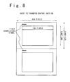
| JPH0479685A (ja) * | 1990-07-23 | 1992-03-13 | Toshiba Corp | テレビ信号の伝送装置 |
| JP3531186B2 (ja) * | 1992-09-18 | 2004-05-24 | ソニー株式会社 | ビデオ信号符号化方法及び装置 |
| US5444491A (en) * | 1993-02-26 | 1995-08-22 | Massachusetts Institute Of Technology | Television system with multiple transmission formats |
| JP3617088B2 (ja) * | 1994-10-20 | 2005-02-02 | 株式会社日立製作所 | テレビジョン受像機 |
| KR960020415A (ko) * | 1994-11-23 | 1996-06-17 | 윌리엄 이. 힐러 | 디지탈 텔레비젼을 위한 특수 기능 |
| KR960028124A (ko) * | 1994-12-30 | 1996-07-22 | 이몬 제이. 월 | 필름 소스에 의해 생성된 비디오 필드 식별 방법 및 장치 |
| US5610661A (en) * | 1995-05-19 | 1997-03-11 | Thomson Multimedia S.A. | Automatic image scanning format converter with seamless switching |
| JP2861902B2 (ja) * | 1995-12-27 | 1999-02-24 | 日本電気株式会社 | 映像信号処理方法と装置 |
| US5754248A (en) * | 1996-04-15 | 1998-05-19 | Faroudja; Yves C. | Universal video disc record and playback employing motion signals for high quality playback of non-film sources |
| JP3698189B2 (ja) * | 1997-11-12 | 2005-09-21 | 株式会社岡村製作所 | キャスター付き家具の免震装置 |
-
1997
- 1997-11-21 JP JP32159797A patent/JP3360586B2/ja not_active Expired - Fee Related
-
1998
- 1998-11-04 US US09/185,710 patent/US6072531A/en not_active Expired - Lifetime
- 1998-11-05 EP EP19980121030 patent/EP0918436B1/de not_active Expired - Lifetime
Patent Citations (4)
| Publication number | Priority date | Publication date | Assignee | Title |
|---|---|---|---|---|
| US5365273A (en) * | 1992-04-24 | 1994-11-15 | Deutsche Thomson-Brandt Gmbh | Method and device for film-mode detection |
| EP0710018A2 (de) * | 1994-10-31 | 1996-05-01 | Victor Company Of Japan, Ltd. | Vorrichtung zum Interpolieren von Abtastzeilen mit einem Bewegungsvektordetektor |
| EP0757482A2 (de) * | 1995-07-31 | 1997-02-05 | Hewlett-Packard Company | System zum Umwandeln von Zeilensprungvideo in Video mit einer progressiven Abtastung auf Basis der Flanken |
| JPH09182032A (ja) * | 1995-12-22 | 1997-07-11 | Hitachi Ltd | 映像信号処理装置 |
Also Published As
| Publication number | Publication date |
|---|---|
| EP0918436A3 (de) | 2000-04-12 |
| US6072531A (en) | 2000-06-06 |
| EP0918436A2 (de) | 1999-05-26 |
| JP3360586B2 (ja) | 2002-12-24 |
| JPH11155132A (ja) | 1999-06-08 |
Similar Documents
| Publication | Publication Date | Title |
|---|---|---|
| EP0918436B1 (de) | Umwandlung von ins Zeilensprung-System dekodiertem Video in Vollbild-Video unter Berücksichtigung des Abtastsystems vor Kodierung | |
| EP0743788B1 (de) | Automatischer Bildabtastformatumwandler mit nahtloser Umschaltung | |
| KR100426890B1 (ko) | 고선명텔레비전시스템에적절한영상주사포맷변환기 | |
| EP1011267B1 (de) | Empfänger zur gleichzeitigen Darstellung von Signalen mit unterschiedlichen Anzeigeformaten und/oder unterschiedlichen Bildraten und deren Anzeigeverfahren | |
| EP0637889A2 (de) | Einrichtung zur Bildformatumsetzung | |
| JPH0795852B2 (ja) | テレビジョン信号用コーディング装置 | |
| EP0933942B1 (de) | Überträger, empfänger und medium für progressives bildsignal | |
| EP0860992B1 (de) | Fernsehempfänger mit Abtastkonverter und entsprechende Methode | |
| JPH0422075B2 (de) | ||
| EP0637175A2 (de) | Bilddatenkodierungsvorrichtung | |
| JP2000500318A (ja) | 適応画像遅延装置 | |
| US7295245B2 (en) | Method and apparatus for converting frame rate using time shifting and motion compensation | |
| JPS61118085A (ja) | 画像信号の符号化方式およびその装置 | |
| JP4119092B2 (ja) | 画像信号のフレーム数変換方法および装置 | |
| US5801777A (en) | Device and method for decoding digital video data | |
| US7092444B2 (en) | Image signal decoder for determining interframe motion | |
| US7239353B2 (en) | Image format conversion apparatus and method | |
| EP1592246A1 (de) | Film-Mode-Bestimmung in unbeweglichen Videobildbereichen | |
| US7012648B2 (en) | Image conversion method and image conversion apparatus | |
| EP1592249B1 (de) | Umkehr-Filmmodus-Extrapolation | |
| US20040017510A1 (en) | Video signal processing apparatus | |
| WO2000011612A1 (en) | Methods and apparatus for reducing the amount of buffer memory required for decoding mpeg data and for performing scan conversion | |
| EP1418754B1 (de) | Auf kodierter Datenströmanalyse basierte Progressivumwandlung von einem Zeilensprungvideo | |
| KR100385975B1 (ko) | 비디오 포맷 변환장치 및 방법 | |
| KR100311009B1 (ko) | 공통 포맷을 이용하는 영상 포맷 변환 장치와 그 방법 |
Legal Events
| Date | Code | Title | Description |
|---|---|---|---|
| PUAI | Public reference made under article 153(3) epc to a published international application that has entered the european phase |
Free format text: ORIGINAL CODE: 0009012 |
|
| AK | Designated contracting states |
Kind code of ref document: A2 Designated state(s): DE GB NL |
|
| AX | Request for extension of the european patent |
Free format text: AL;LT;LV;MK;RO;SI |
|
| PUAL | Search report despatched |
Free format text: ORIGINAL CODE: 0009013 |
|
| AK | Designated contracting states |
Kind code of ref document: A3 Designated state(s): AT BE CH CY DE DK ES FI FR GB GR IE IT LI LU MC NL PT SE |
|
| AX | Request for extension of the european patent |
Free format text: AL;LT;LV;MK;RO;SI |
|
| 17P | Request for examination filed |
Effective date: 20000302 |
|
| AKX | Designation fees paid |
Free format text: DE GB NL |
|
| 17Q | First examination report despatched |
Effective date: 20040903 |
|
| RAP1 | Party data changed (applicant data changed or rights of an application transferred) |
Owner name: ACER INCORPORATED |
|
| REG | Reference to a national code |
Ref country code: DE Ref legal event code: R079 Ref document number: 69842561 Country of ref document: DE Free format text: PREVIOUS MAIN CLASS: H04N0005440000 Ipc: H04N0007010000 |
|
| RIC1 | Information provided on ipc code assigned before grant |
Ipc: H04N 7/01 20060101AFI20110418BHEP |
|
| RTI1 | Title (correction) |
Free format text: CONVERSION OF DECODED INTERLACED VIDEO INTO PROGRESSIVE SCANNING SYSTEM TAKING ACCOUNT OF SCANNING SYSTEM BEFORE CODING |
|
| GRAP | Despatch of communication of intention to grant a patent |
Free format text: ORIGINAL CODE: EPIDOSNIGR1 |
|
| RIN1 | Information on inventor provided before grant (corrected) |
Inventor name: SHIBANO, MOTOYOSHI |
|
| GRAS | Grant fee paid |
Free format text: ORIGINAL CODE: EPIDOSNIGR3 |
|
| GRAA | (expected) grant |
Free format text: ORIGINAL CODE: 0009210 |
|
| AK | Designated contracting states |
Kind code of ref document: B1 Designated state(s): DE GB NL |
|
| REG | Reference to a national code |
Ref country code: GB Ref legal event code: FG4D |
|
| REG | Reference to a national code |
Ref country code: DE Ref legal event code: R096 Ref document number: 69842561 Country of ref document: DE Effective date: 20120315 |
|
| REG | Reference to a national code |
Ref country code: NL Ref legal event code: T3 |
|
| PLBE | No opposition filed within time limit |
Free format text: ORIGINAL CODE: 0009261 |
|
| STAA | Information on the status of an ep patent application or granted ep patent |
Free format text: STATUS: NO OPPOSITION FILED WITHIN TIME LIMIT |
|
| 26N | No opposition filed |
Effective date: 20121012 |
|
| REG | Reference to a national code |
Ref country code: DE Ref legal event code: R097 Ref document number: 69842561 Country of ref document: DE Effective date: 20121012 |
|
| PGFP | Annual fee paid to national office [announced via postgrant information from national office to epo] |
Ref country code: DE Payment date: 20171031 Year of fee payment: 20 |
|
| PGFP | Annual fee paid to national office [announced via postgrant information from national office to epo] |
Ref country code: NL Payment date: 20171016 Year of fee payment: 20 Ref country code: GB Payment date: 20171101 Year of fee payment: 20 |
|
| REG | Reference to a national code |
Ref country code: DE Ref legal event code: R071 Ref document number: 69842561 Country of ref document: DE |
|
| REG | Reference to a national code |
Ref country code: NL Ref legal event code: MK Effective date: 20181104 |
|
| REG | Reference to a national code |
Ref country code: GB Ref legal event code: PE20 Expiry date: 20181104 |
|
| PG25 | Lapsed in a contracting state [announced via postgrant information from national office to epo] |
Ref country code: GB Free format text: LAPSE BECAUSE OF EXPIRATION OF PROTECTION Effective date: 20181104 |