EP0917172A2 - Schutzschalter mit einem Anschlussdeckel der mit einer Anordnung zür Führung elektrischer Drähte Ausgestattet ist - Google Patents
Schutzschalter mit einem Anschlussdeckel der mit einer Anordnung zür Führung elektrischer Drähte Ausgestattet ist Download PDFInfo
- Publication number
- EP0917172A2 EP0917172A2 EP98120680A EP98120680A EP0917172A2 EP 0917172 A2 EP0917172 A2 EP 0917172A2 EP 98120680 A EP98120680 A EP 98120680A EP 98120680 A EP98120680 A EP 98120680A EP 0917172 A2 EP0917172 A2 EP 0917172A2
- Authority
- EP
- European Patent Office
- Prior art keywords
- power terminals
- switch housing
- terminals
- circuit breaker
- switching device
- Prior art date
- Legal status (The legal status is an assumption and is not a legal conclusion. Google has not performed a legal analysis and makes no representation as to the accuracy of the status listed.)
- Granted
Links
Images


Classifications
-
- H—ELECTRICITY
- H01—ELECTRIC ELEMENTS
- H01H—ELECTRIC SWITCHES; RELAYS; SELECTORS; EMERGENCY PROTECTIVE DEVICES
- H01H71/00—Details of the protective switches or relays covered by groups H01H73/00 - H01H83/00
- H01H71/08—Terminals; Connections
-
- H—ELECTRICITY
- H01—ELECTRIC ELEMENTS
- H01H—ELECTRIC SWITCHES; RELAYS; SELECTORS; EMERGENCY PROTECTIVE DEVICES
- H01H71/00—Details of the protective switches or relays covered by groups H01H73/00 - H01H83/00
- H01H71/08—Terminals; Connections
- H01H2071/086—Low power connections for auxiliary switches, e.g. shunt trip
-
- H—ELECTRICITY
- H01—ELECTRIC ELEMENTS
- H01H—ELECTRIC SWITCHES; RELAYS; SELECTORS; EMERGENCY PROTECTIVE DEVICES
- H01H9/00—Details of switching devices, not covered by groups H01H1/00 - H01H7/00
- H01H9/02—Bases, casings, or covers
- H01H9/0264—Protective covers for terminals
Definitions
- the subject matter of this invention is related generally to molded case circuit breakers and more particularly to terminal shield arrangements for molded case circuit breakers.
- Molded case circuit breakers are known generally in the art.
- U.S. Patent 4,644,120 entitled “Molded Case Circuit Breaker with a Movable Lower Electrical Contact Positioned by a Torsion Spring” issued February 17, 1987 and now transferred to the present assignee, teaches a molded case circuit breaker of the kind having terminals at each end thereof for interconnection with load and line conductors of a given voltage which may be, or example, voltages such as 120 or 240 volts act
- load and line conductors of a given voltage which may be, or example, voltages such as 120 or 240 volts act
- the relatively low voltage accessory wiring which may be 10, 12 or 40 volts for example, is routed out of the molded case circuit breaker to other positions for providing electrical conductivity to and from the molded case circuit breaker.
- One of the disadvantages of having the relatively low voltage control or auxiliary wiring is the fact that it may be routed in or near the load or line wiring which is at a relatively higher voltage. As can be appreciated, even though the wires are insulated, having voltages of different values conducted by conductors in close proximity to each may introduce an opportunity for short circuit, flash over and other inadvertent electrical contact, etc. This would be detrimental to either the load, line or the low voltage auxiliary elements depending upon the circumstances.
- a switching apparatus for an electrical power circuit includes a switch housing and a switching device mounded within the switch housing.
- Power terminals are provided for connecting the switching device to an electrical circuit.
- the power terminals are at the face of the switch housing and dispose in space relationship therein.
- An attachment device is connecting in the housing to the switching device and has external leads exiting the switch housing adjacent to power terminals.
- a terminals shield is provided which is interconnected with the housing adjacent to the power terminals for shielding the power terminals and furthermore for having interphase barrier therein for separating the power terminals, one from the other and finally for having longitudinally extending passages therein through which the aforementioned low voltage electrical leads are routed.
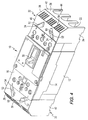
- molded case circuit breaker 10 with two partially broken away end shields 32 is depicted.
- Molded case circuit breaker 10 is of the type shown and described in U.S. Patent 4,644,120 originally assigned to the Westinghouse Electric Corporation and now assigned by Agreement to the assignee of the present invention and incorporated herein by reference.
- molded case circuit breaker 10 may included a lower housing 12 and an upper housing 14 which together join to form an enclosure for enclosing standard molded case circuit breaker parts, such as trip mechanisms, operating mechanisms, and separable main contacts all of which are described in the previously mentioned incorporated-by-reference patent.
- There may also be provided a top cover or auxiliary cover 16 which fits on top of the top portion 14.
- Circuit breaker 10 may include openings 18 on one end thereof and 20 on the other end thereof which provide access to LOAD and LINE terminals 22 (not shown). There may be also provided at least one opening 24 extended into the internal region of the circuit breaker from which secondary, accessory or low voltage control wiring 26 may extend. There are provided in the circuit breaker case on the front and back (not shown) two longitudinal, stepped openings 28 which may be utilized for mounting terminal the shield apparatus 32 in a manner which will be described herein after. There is provided on the top of the case protruding through an opening therein a handle 30 (see Figures 4 and 5). The handle 30 may be in the ON, OFF or RESET state, depending upon the status of mechanisms with the circuit breaker 10.
- Shield arrangement 32 includes a set of parallel spaced apart side walls 34 and 42 which generally align with the sides of the circuit breaker 10 at the ends thereof. There is provided a transverse barrier on back wall 36 joining the side walls 34 and 32. Back wall 36 is generally parallel to the ends of the circuit breaker 10.
- a canted wall portion 38 traverses the region between the side walls 34 and 42 and joins the end region 36 with a transverse top wall 40.
- Canted wall region 38 has slots or openings 39 therein which may be utilized to conduct heat away from the main terminals 22 (not shown) protected by the shield 32.
- openings 44 which extend from the bottom thereof to semicircular arc regions on the top. It is through these openings 44 that the main electrical conductors for the LOAD or the LINE terminals 22 may protrude after connection has been made. There is also shown two interphase barriers 46 that separate the regions of the three conductors which protrude through the openings 44, as would normally be he case in a three phase electrical system. There are provided on the opposite side of the shield from the end wall 36 two stepped longitudinal tabs 50 having a first extending tab region 50A, a stepped down tab region SOB, and a further stepped down tab region 50C.
- Tabs 50A and B align with the corresponding portions of openings 28 on the top 14 and bottom 12 of the molded case circuit breaker, such that tab 50A extends into the top portion of the circuit breaker 14 and tab 50B extends into the bottom portion of the circuit breaker 12 as shown in Fig. 1.
- control wiring 26 in the channel 52 and the wire troughs 60 isolates the low voltage control wiring from the high voltage line or load wiring which protrudes transversally through the openings 44 on the shield 32 for jointure to the LOAD or LINE terminals 22 as the case may be.
- FIG. 4 and 5 the molded case circuit breaker 10 of figure one is shown with two complimentary shield members 32 at each end thereof to form the fully constructed, double shielded, molded case circuit breaker arrangement depicted in Figures 4 and 5.
- Figures 4 and 5 the reference characters depicted therein are defined in Figures 1 through 3.
- the shield arrangement is not limited to a 3-phase, ac shield arrangements. Nor is it required that there be a shield arrangement at both ends of the circuit interrupter as shown in Figures 4 and 5. It is also to be understood that the shield arrangement may be utilized even if there is no control wiring 26 present or if the control wiring 26 is utilized in a different part of the circuit breaker to follow a different exit route. It is also to be understood that the shield arrangement though described with respect to a molded case circuit breaker may be utilized with any electrical apparatus in which it is desired to shield the terminals thereof and/or provide interphase barriers and/or provide alternate safe routing for wiring of a different voltage level from the main load wiring.
- the apparatus taught herein has many advantages.
- One of the advantages lies in the fact that a single shield arrangement may be utilized to provide the three fold function of: Main terminal protection, interphase barrier protection and alternate wiring channels for lower voltage wiring.
Landscapes
- Breakers (AREA)
Applications Claiming Priority (2)
| Application Number | Priority Date | Filing Date | Title |
|---|---|---|---|
| US969557 | 1997-11-13 | ||
| US08/969,557 US5933066A (en) | 1997-11-13 | 1997-11-13 | Circuit interrupter with terminal shield and wire trough |
Publications (3)
| Publication Number | Publication Date |
|---|---|
| EP0917172A2 true EP0917172A2 (de) | 1999-05-19 |
| EP0917172A3 EP0917172A3 (de) | 2000-10-11 |
| EP0917172B1 EP0917172B1 (de) | 2004-04-28 |
Family
ID=25515676
Family Applications (1)
| Application Number | Title | Priority Date | Filing Date |
|---|---|---|---|
| EP98120680A Expired - Lifetime EP0917172B1 (de) | 1997-11-13 | 1998-11-05 | Schutzschalter mit einem Anschlussdeckel der mit einer Anordnung zur Führung elektrischer Drähte ausgestattet ist |
Country Status (8)
| Country | Link |
|---|---|
| US (1) | US5933066A (de) |
| EP (1) | EP0917172B1 (de) |
| CN (1) | CN1129942C (de) |
| CA (1) | CA2253966C (de) |
| DE (1) | DE69823455T2 (de) |
| ID (1) | ID21252A (de) |
| MY (1) | MY114972A (de) |
| TW (1) | TW385460B (de) |
Cited By (3)
| Publication number | Priority date | Publication date | Assignee | Title |
|---|---|---|---|---|
| WO2001016974A1 (en) * | 1999-08-30 | 2001-03-08 | Eaton Corporation | Circuit interrupter with improved terminal shield and shield cover |
| WO2001069739A1 (fr) * | 2000-03-17 | 2001-09-20 | Ge Power Controls France | Support de disjoncteur et ensemble-disjoncteur |
| US6509692B2 (en) | 2000-07-31 | 2003-01-21 | Sanyo Electric Co., Ltd. | Self-emissive display device of active matrix type and organic EL display device of active matrix type |
Families Citing this family (18)
| Publication number | Priority date | Publication date | Assignee | Title |
|---|---|---|---|---|
| US6388217B1 (en) * | 2000-09-05 | 2002-05-14 | Eaton Corporation | Electric power switch with stain relief for attachment wiring |
| JP4288868B2 (ja) * | 2001-05-28 | 2009-07-01 | 富士電機機器制御株式会社 | 回路しゃ断器の付属スイッチ装置 |
| JP2003257299A (ja) * | 2002-03-06 | 2003-09-12 | Fuji Electric Co Ltd | 回路遮断器 |
| US6700060B1 (en) | 2002-08-29 | 2004-03-02 | Eaton Corporation | Auxiliary wiring trough |
| FR2850203B1 (fr) * | 2003-01-20 | 2005-02-25 | Schneider Electric Ind Sas | Boitier de coupure d'un appareil electrique interrupteur |
| CN1312719C (zh) * | 2004-12-14 | 2007-04-25 | 常熟开关制造有限公司(原常熟开关厂) | 塑壳断路器 |
| US8901446B2 (en) * | 2011-02-08 | 2014-12-02 | Siemens Aktiengesellschaft | Limit stop apparatus, circuit breakers including limit stops, and methods of using same |
| US8859918B2 (en) * | 2012-12-05 | 2014-10-14 | Eaton Corporation | Circuit breaker terminal shield with position indicator |
| US9548170B2 (en) | 2015-01-19 | 2017-01-17 | Eaton Corporation | Electrical switching apparatus with terminal guard assembly |
| CN104701102A (zh) * | 2015-03-20 | 2015-06-10 | 浪潮集团有限公司 | 一种基于k1的空气开关保护罩 |
| US10068720B2 (en) | 2016-05-12 | 2018-09-04 | Eaton Intelligent Power Limited | Electrical system, and electrical switching apparatus and guard member therefor |
| US9928974B1 (en) | 2016-09-16 | 2018-03-27 | Siemens Industry, Inc. | Terminal barrier assemblies for electrical switching apparatus and methods of assembly thereof |
| US10037856B2 (en) | 2016-09-23 | 2018-07-31 | Eaton Intelligent Power Limited | Electrical system, and electrical switching apparatus and guard member therefor |
| US9916939B1 (en) * | 2016-11-11 | 2018-03-13 | General Electric Company | Electrical distribution apparatus including barrier and methods of assembling same |
| CN111417884B (zh) * | 2017-12-01 | 2022-07-29 | 浜松光子学株式会社 | 致动器装置 |
| JP6585147B2 (ja) * | 2017-12-01 | 2019-10-02 | 浜松ホトニクス株式会社 | アクチュエータ装置 |
| CN109378260A (zh) * | 2018-10-08 | 2019-02-22 | 庞江涛 | 一种断路器用接线端子防护壳 |
| CN111755269A (zh) * | 2020-08-04 | 2020-10-09 | 广东泉胜电工有限公司 | 一种具有安全装线结构的开关 |
Citations (4)
| Publication number | Priority date | Publication date | Assignee | Title |
|---|---|---|---|---|
| JPH02183931A (ja) * | 1989-01-06 | 1990-07-18 | Fuji Electric Co Ltd | 付属装置のリード線引出し構造 |
| US5150091A (en) * | 1990-11-08 | 1992-09-22 | General Electric Company | Bus cover and lug cover for a molded case circuit breaker |
| EP0588712A1 (de) * | 1992-09-16 | 1994-03-23 | Schneider Electric Sa | Verbindungsstück für die Verbindung von einem Schaltschutz mit einem Schutzschalter |
| EP0881727A2 (de) * | 1997-05-28 | 1998-12-02 | Eaton Corporation | Kombinierte Drahtführung und elektrische Phasentrennung für Leitungsschalter |
Family Cites Families (1)
| Publication number | Priority date | Publication date | Assignee | Title |
|---|---|---|---|---|
| US5321378A (en) * | 1993-04-08 | 1994-06-14 | General Electric Company | Molded case circuit breaker current transformer adapter unit |
-
1997
- 1997-11-13 US US08/969,557 patent/US5933066A/en not_active Expired - Lifetime
-
1998
- 1998-10-29 TW TW087117934A patent/TW385460B/zh not_active IP Right Cessation
- 1998-11-05 DE DE69823455T patent/DE69823455T2/de not_active Expired - Lifetime
- 1998-11-05 EP EP98120680A patent/EP0917172B1/de not_active Expired - Lifetime
- 1998-11-11 ID IDP981474A patent/ID21252A/id unknown
- 1998-11-12 CA CA002253966A patent/CA2253966C/en not_active Expired - Lifetime
- 1998-11-12 MY MYPI98005125A patent/MY114972A/en unknown
- 1998-11-13 CN CN98122307.9A patent/CN1129942C/zh not_active Expired - Fee Related
Patent Citations (4)
| Publication number | Priority date | Publication date | Assignee | Title |
|---|---|---|---|---|
| JPH02183931A (ja) * | 1989-01-06 | 1990-07-18 | Fuji Electric Co Ltd | 付属装置のリード線引出し構造 |
| US5150091A (en) * | 1990-11-08 | 1992-09-22 | General Electric Company | Bus cover and lug cover for a molded case circuit breaker |
| EP0588712A1 (de) * | 1992-09-16 | 1994-03-23 | Schneider Electric Sa | Verbindungsstück für die Verbindung von einem Schaltschutz mit einem Schutzschalter |
| EP0881727A2 (de) * | 1997-05-28 | 1998-12-02 | Eaton Corporation | Kombinierte Drahtführung und elektrische Phasentrennung für Leitungsschalter |
Non-Patent Citations (1)
| Title |
|---|
| PATENT ABSTRACTS OF JAPAN vol. 014, no. 457 (E-0986), 2 October 1990 (1990-10-02) -& JP 02 183931 A (FUJI ELECTRIC CO LTD), 18 July 1990 (1990-07-18) * |
Cited By (4)
| Publication number | Priority date | Publication date | Assignee | Title |
|---|---|---|---|---|
| WO2001016974A1 (en) * | 1999-08-30 | 2001-03-08 | Eaton Corporation | Circuit interrupter with improved terminal shield and shield cover |
| WO2001069739A1 (fr) * | 2000-03-17 | 2001-09-20 | Ge Power Controls France | Support de disjoncteur et ensemble-disjoncteur |
| FR2806547A1 (fr) * | 2000-03-17 | 2001-09-21 | Ge Power Controls France | Support de disjoncteur et ensemble-disjoncteur |
| US6509692B2 (en) | 2000-07-31 | 2003-01-21 | Sanyo Electric Co., Ltd. | Self-emissive display device of active matrix type and organic EL display device of active matrix type |
Also Published As
| Publication number | Publication date |
|---|---|
| ID21252A (id) | 1999-05-12 |
| CN1129942C (zh) | 2003-12-03 |
| MY114972A (en) | 2003-02-28 |
| EP0917172B1 (de) | 2004-04-28 |
| DE69823455T2 (de) | 2005-03-03 |
| CA2253966A1 (en) | 1999-05-13 |
| CN1217558A (zh) | 1999-05-26 |
| TW385460B (en) | 2000-03-21 |
| DE69823455D1 (de) | 2004-06-03 |
| EP0917172A3 (de) | 2000-10-11 |
| US5933066A (en) | 1999-08-03 |
| CA2253966C (en) | 2007-03-27 |
Similar Documents
| Publication | Publication Date | Title |
|---|---|---|
| EP0917172B1 (de) | Schutzschalter mit einem Anschlussdeckel der mit einer Anordnung zur Führung elektrischer Drähte ausgestattet ist | |
| US5124881A (en) | Enclosed switchgear | |
| JP4910913B2 (ja) | 漏電遮断器 | |
| EP2515318B1 (de) | Kompakte Busschienenanordnung, Schaltvorrichtung und Energieverteilungssystem | |
| CA2238724C (en) | Combined wire lead and interphase barrier for power switches | |
| US4543455A (en) | Explosion-proof switching installation with a bus bar duct | |
| CN111312559B (zh) | 配线用断路器 | |
| EP0092774A2 (de) | Schalttafel | |
| US6175486B1 (en) | Switch gear for medium voltage with separately connectable multiple phases | |
| CN110875164B (zh) | 配线用断路器 | |
| TW200522112A (en) | Vacuum switchgear system | |
| JP2000188805A (ja) | 分電盤の接続導体装置 | |
| JPH11297179A (ja) | 回路遮断器およびその主回路端子アダプタ | |
| US20020027489A1 (en) | Circuit breaker support and assembly | |
| CN116157973A (zh) | 配电盘 | |
| JP3843675B2 (ja) | 多極開閉器の端子ユニット | |
| WO2002054432A1 (en) | Supporting base for a circuit breaker | |
| US11257648B2 (en) | Electronic trip device for molded case circuit breaker | |
| NO319544B1 (no) | Modulaert elektrisk apparat som plugges inn i en isolert distribusjonsblokk | |
| KR200162957Y1 (ko) | 회로보호용 차단기의 단자부 절연장치 | |
| JPH0746002Y2 (ja) | 分電盤 | |
| KR200156759Y1 (ko) | 배선용 차단기 | |
| JPH1196879A (ja) | 回路遮断器 | |
| JPH09298026A (ja) | 多極回路遮断器 | |
| JPH04312732A (ja) | 回路遮断器の内部リード線の配線方法 |
Legal Events
| Date | Code | Title | Description |
|---|---|---|---|
| PUAI | Public reference made under article 153(3) epc to a published international application that has entered the european phase |
Free format text: ORIGINAL CODE: 0009012 |
|
| AK | Designated contracting states |
Kind code of ref document: A2 Designated state(s): DE FR GB IT |
|
| AX | Request for extension of the european patent |
Free format text: AL;LT;LV;MK;RO;SI |
|
| PUAL | Search report despatched |
Free format text: ORIGINAL CODE: 0009013 |
|
| AK | Designated contracting states |
Kind code of ref document: A3 Designated state(s): AT BE CH CY DE DK ES FI FR GB GR IE IT LI LU MC NL PT SE |
|
| AX | Request for extension of the european patent |
Free format text: AL;LT;LV;MK;RO;SI |
|
| 17P | Request for examination filed |
Effective date: 20010312 |
|
| AKX | Designation fees paid |
Free format text: DE FR GB IT |
|
| GRAP | Despatch of communication of intention to grant a patent |
Free format text: ORIGINAL CODE: EPIDOSNIGR1 |
|
| GRAS | Grant fee paid |
Free format text: ORIGINAL CODE: EPIDOSNIGR3 |
|
| GRAA | (expected) grant |
Free format text: ORIGINAL CODE: 0009210 |
|
| AK | Designated contracting states |
Kind code of ref document: B1 Designated state(s): DE FR GB IT |
|
| REG | Reference to a national code |
Ref country code: GB Ref legal event code: FG4D |
|
| REF | Corresponds to: |
Ref document number: 69823455 Country of ref document: DE Date of ref document: 20040603 Kind code of ref document: P |
|
| ET | Fr: translation filed | ||
| PLBE | No opposition filed within time limit |
Free format text: ORIGINAL CODE: 0009261 |
|
| STAA | Information on the status of an ep patent application or granted ep patent |
Free format text: STATUS: NO OPPOSITION FILED WITHIN TIME LIMIT |
|
| 26N | No opposition filed |
Effective date: 20050131 |
|
| PGFP | Annual fee paid to national office [announced via postgrant information from national office to epo] |
Ref country code: GB Payment date: 20081008 Year of fee payment: 11 |
|
| PGFP | Annual fee paid to national office [announced via postgrant information from national office to epo] |
Ref country code: DE Payment date: 20091130 Year of fee payment: 12 |
|
| GBPC | Gb: european patent ceased through non-payment of renewal fee |
Effective date: 20091105 |
|
| PG25 | Lapsed in a contracting state [announced via postgrant information from national office to epo] |
Ref country code: GB Free format text: LAPSE BECAUSE OF NON-PAYMENT OF DUE FEES Effective date: 20091105 |
|
| REG | Reference to a national code |
Ref country code: DE Ref legal event code: R119 Ref document number: 69823455 Country of ref document: DE Effective date: 20110601 Ref country code: DE Ref legal event code: R119 Ref document number: 69823455 Country of ref document: DE Effective date: 20110531 |
|
| PG25 | Lapsed in a contracting state [announced via postgrant information from national office to epo] |
Ref country code: DE Free format text: LAPSE BECAUSE OF NON-PAYMENT OF DUE FEES Effective date: 20110531 |
|
| PGFP | Annual fee paid to national office [announced via postgrant information from national office to epo] |
Ref country code: FR Payment date: 20131025 Year of fee payment: 16 |
|
| PGFP | Annual fee paid to national office [announced via postgrant information from national office to epo] |
Ref country code: IT Payment date: 20131121 Year of fee payment: 16 |
|
| REG | Reference to a national code |
Ref country code: FR Ref legal event code: ST Effective date: 20150731 |
|
| PG25 | Lapsed in a contracting state [announced via postgrant information from national office to epo] |
Ref country code: FR Free format text: LAPSE BECAUSE OF NON-PAYMENT OF DUE FEES Effective date: 20141201 |
|
| PG25 | Lapsed in a contracting state [announced via postgrant information from national office to epo] |
Ref country code: IT Free format text: LAPSE BECAUSE OF NON-PAYMENT OF DUE FEES Effective date: 20141105 |