EP0917168B1 - Mécanisme d'entrainement à ressort pour un appareil de commutation, en particulier un disjoncteur - Google Patents
Mécanisme d'entrainement à ressort pour un appareil de commutation, en particulier un disjoncteur Download PDFInfo
- Publication number
- EP0917168B1 EP0917168B1 EP98402807A EP98402807A EP0917168B1 EP 0917168 B1 EP0917168 B1 EP 0917168B1 EP 98402807 A EP98402807 A EP 98402807A EP 98402807 A EP98402807 A EP 98402807A EP 0917168 B1 EP0917168 B1 EP 0917168B1
- Authority
- EP
- European Patent Office
- Prior art keywords
- wheel
- tooth
- retractable
- gap
- teeth
- Prior art date
- Legal status (The legal status is an assumption and is not a legal conclusion. Google has not performed a legal analysis and makes no representation as to the accuracy of the status listed.)
- Expired - Lifetime
Links
- 230000007246 mechanism Effects 0.000 title claims description 31
- 230000006835 compression Effects 0.000 claims description 8
- 238000007906 compression Methods 0.000 claims description 8
- 230000007935 neutral effect Effects 0.000 description 5
- 239000011295 pitch Substances 0.000 description 5
- 230000008878 coupling Effects 0.000 description 3
- 238000010168 coupling process Methods 0.000 description 3
- 238000005859 coupling reaction Methods 0.000 description 3
- 210000004027 cell Anatomy 0.000 description 2
- 230000000295 complement effect Effects 0.000 description 2
- 241000251468 Actinopterygii Species 0.000 description 1
- 241000287107 Passer Species 0.000 description 1
- 230000008901 benefit Effects 0.000 description 1
- 230000000903 blocking effect Effects 0.000 description 1
- 210000000988 bone and bone Anatomy 0.000 description 1
- 238000010276 construction Methods 0.000 description 1
- 230000007257 malfunction Effects 0.000 description 1
- 238000000034 method Methods 0.000 description 1
- 230000008569 process Effects 0.000 description 1
- 230000000750 progressive effect Effects 0.000 description 1
- 230000000284 resting effect Effects 0.000 description 1
- 230000009466 transformation Effects 0.000 description 1
Images


Classifications
-
- H—ELECTRICITY
- H01—ELECTRIC ELEMENTS
- H01H—ELECTRIC SWITCHES; RELAYS; SELECTORS; EMERGENCY PROTECTIVE DEVICES
- H01H3/00—Mechanisms for operating contacts
- H01H3/22—Power arrangements internal to the switch for operating the driving mechanism
- H01H3/30—Power arrangements internal to the switch for operating the driving mechanism using spring motor
- H01H3/3005—Charging means
-
- H—ELECTRICITY
- H01—ELECTRIC ELEMENTS
- H01H—ELECTRIC SWITCHES; RELAYS; SELECTORS; EMERGENCY PROTECTIVE DEVICES
- H01H3/00—Mechanisms for operating contacts
- H01H3/22—Power arrangements internal to the switch for operating the driving mechanism
- H01H3/30—Power arrangements internal to the switch for operating the driving mechanism using spring motor
- H01H2003/3063—Decoupling charging handle or motor at end of charging cycle or during charged condition
Definitions
- a shape of the teeth of said toothed pinion whose flanks join, radially outward, on a common edge and have, on the leading flank, an involute shape and, on the opposite flank, a flank plane starting from the edge and which is inclined relative to a radial straight line passing through the middle of the tooth, and, a shape of the tooth of the large toothed wheel which occurs after the release, in said predetermined direction, the sides of which join radially outward on a common edge and which has an inclined plane in its upper zone adjacent to the fish bone.
- European patent No 0 294 561 A2 describes a drive mechanism of a similar type, coupled to a disconnector and the first tooth of the large gear wheel, which is located immediately after the release, is radially retractable against the stress of a compression spring. Yes this tooth abuts against the top of a tooth of the toothed pinion, at the beginning of the latching process, it retracts radially by compressing the spring associated with it. As a result, this tooth can slide without generating blocking on the edge of the corresponding tooth of the toothed pinion. When she has beyond this edge, it engages in the hollow which follows the tooth of the pinion toothed.
- the present invention proposes to remedy all of these disadvantages and remove the risk of malfunctions of these known mechanisms offering an effective solution, simple to carry out, little expensive and which can also be adapted by a transformation appropriate, to mechanisms of this type that are already in use.
- This goal is achieved by the mechanism as defined in the preamble and characterized in that said first clearance provided at the periphery of said large the toothed wheel is followed, in said predetermined direction of rotation, by a first radially retractable tooth against the constraint of a spring of compression, in that said first retractable tooth is followed, in said predetermined direction of rotation, from a second clearance provided at the periphery of this large gear wheel, generated by a discontinuity complementary to the teeth, this second clearance extending over at minus two gear steps, and in that the tooth that immediately follows said second clearance is a second radially retractable tooth against the stress of a compression spring.
- said second clearance extends over a length slightly less than an integer number of gear steps and said second retractable tooth has flanks which join radially towards the exterior, on a common edge, and which have an inclined plane in its upper zone adjacent to the edge.
- said second clearance extends over a length approximately 116 less than a gear step to an integer gear pitch and preferably over an approximate length equal to 2 (5/6) of gear pitch.
- said second tooth retractable is followed, in said predetermined direction of rotation, by a third clearance which extends over at least two gear pitches.
- said third clearance is followed by a tooth whose the flanks join radially outward, on a common edge, and which has an inclined plane in its upper zone adjacent to the edge.
- said first clearance is followed, in the predetermined direction of rotation, of n teeth retractable axially against the spring stress, each of these retractable teeth being followed, in said predetermined direction of rotation, by a clearance extending over at least two gear steps.
- said retractable teeth and the first non-retractable tooth following the last retractable tooth, in the predetermined direction of rotation have flanks which join radially towards the exterior, on a common edge, and which have an inclined plane in their upper zone adjacent to the edge.
- Said retractable teeth are advantageously separated from the two teeth neighboring retractable by a clearance extending over a length slightly less than a whole number of gear steps.
- the spring drive mechanism 10 as shown intended to be coupled to a switching device, comprises a interlocking shaft 11, freely rotatable about its axis 12 and bearing on the one hand a large toothed wheel 13 and on the other hand a cam 14 whose function will be explained later.
- An engagement spring 15, consisting by a tension spring, is coupled to the large toothed wheel 13 at a point attachment 16, via a chain 17, or any other means suitable, which passes over an angular pulley 18 in the example represented.
- the large toothed wheel 13 meshes with a toothed pinion 19 which is coupled via a gear train 20 to a drive pinion 21 integral an output shaft 22 of a drive motor 23.
- the engagement spring 15 exerts a traction on the chain 17 and causes the rotation of the large gear 13, in the predetermined direction indicated by arrow A, the attachment point 16 passing from a standby position slightly downstream from neutral 16a (in the predetermined direction of rotation A of the large toothed wheel), at a final position corresponding to a relaxation point 16b which is diametrically opposite to neutral 16a.
- the engine 23 takes over to drive the drive shaft 11 rotating in the predetermined direction of rotation A. This movement is continues until the point where the interlocking spring is attached again slightly exceeds the neutral point 16a and where this spring is armed.
- a ratchet mechanism 24 which comprises a ratchet 25 actuated by an electromagnet 26 and a stop 27 mounted on one of the faces of the large wheel tooth 13, which cooperates with the pawl 25 to stop this wheel in the desired waiting position.
- the mechanism 10 comprises a main shaft 30 which in particular carries an actuating lever 31 of a lever (not shown) of the switching device, a coupling lever 32 of this shaft to a trigger spring 33, a roller carrier lever 34 which carries a cam follower roller 34a which cooperates with the cam 14, a locking lever 35 which cooperates with a pawl 36 actuated by an electromagnet 37 and a braking lever which is coupled to a brake 38 constituted for example by an oil jack or the like.
- the trigger spring 33 is preferably identical or similar to the engagement spring 15 and is connected by means of a chain 39 guided by an angular pulley 40 to the coupling lever 32.
- the cam follower roller 34a is resting against the cam 14 mounted on the engagement shaft 11.
- This cam controls the movement of the lever 34 between two positions 41 a and 41 b which correspond respectively to the positions l and O of the actuating lever 31.
- the pawl 36 ensures the locking lever 35 is locked in a position which corresponds to position l of the actuating lever 31.
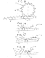
- Figure 2 shows, on an enlarged scale, part of the Ferris wheel toothed 13 and the toothed pinion 19.
- the teeth 50 of the pinion 19 have a particular geometry which corresponds to a point size.
- the flanks of these teeth join radially outward on an edge common and present, on the flank of attack, a developing form and on the opposite flank, a plane starting from the edge and which is inclined relative to a radial straight line passing through the middle of the corresponding tooth.
- the large toothed wheel 13 comprises, in the predetermined direction of rotation A, a discontinuity in the toothing 51, this discontinuity generating a first clearance 52a which constitutes an area without teeth.
- a first tooth retractable 53a is arranged in this clearance. It is integral with a partially hollowed socket 54a which is housed in a recess 55a substantially cylindrical, formed in the thickness of the large gear.
- a compression spring 56a is mounted in the closed space delimited between the cavity of the hollowed-out sleeve 54a and the recess 55a of the wheel, this spring having tendency to push tooth 53a radially to the outside of the wheel.
- a stop plate 57a is fixed to the bottom of the first clearance 52a so partially closing the recess 55a.
- This stop plate is fixed to the by means of at least one and preferably two locking screws 58a. Thanks to this assembly, the tooth 53a can partially retract inside of recess 55a, contrary to the constraint exerted by the spring of compression 56a.
- the large wheel 13 has a second clearance 52b which is generated by a discontinuity complementary to the toothing 51 of this wheel.
- This second release extends over at least two gear pitches. According to one embodiment preferred, this clearance extends over a length slightly less than one whole number of gear steps and advantageously on a whole number, for example three gear steps reduced by 1/6 gear step.
- the tooth 53b of the toothing of the large toothed wheel, which follows said second clearance 52b, is also retractable under the constraint of a spring compression 56b.
- the tooth 60 which follows the second retractable tooth 53b, after a third clearance 52c which extends over a length equal to a number whole gear pitch, includes, as well as each of the teeth retractable, sides which join radially outwards on a common edge.
- the flank opposite the leading flank has an inclined plane in its upper part adjacent to the edge of the tooth.
- the two retractable teeth 53a and 53b can be prominent compared to the other teeth 51 of the teeth of the large gear wheel, this which has the advantage of reducing the probability that the tip of said others teeth comes into contact with the tip of a pinion tooth 19.
- Figures 3A to 3H illustrate what happens in the absence of a collision between the teeth 50 of the pinion 19 and the teeth of the large gear wheel 13.
- the instant initial is represented by figures 3A and 3B, this last figure representing the coming into contact of a tooth of the pinion 19 and the first retractable tooth 53a of the large gear wheel 13.
- Figures 3C and 3D show the relative position of the sprocket teeth relative to the teeth 51 missing, shown in broken lines, of the large gear wheel 13.
- FIG. 3E illustrates in broken lines the primitive shape of a tooth 61 pinion 19 not cut appropriately. We see in this figure that if this shape were maintained, it would automatically cause a collision with the second retractable tooth 53b of the large toothed wheel.
- the following figures 3F, 3G and 3H illustrate the relative positions of the teeth 50 of the pinion 19 and 53a, 53b and 60 of the large gear 13.
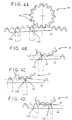
- Figures 4A to 4H illustrate what happens when the tip of a tooth 50 pinion 19 meets the tip of the retractable tooth 53a of the ferris wheel toothed 13.
- the initial instant of this contact between the two teeth 50 and 53a is shown in Figure 4B.
- Point-to-point contact causes tooth retraction 53a.
- Figures 4C and 4D illustrate the teeth of the pinion and those of the big gear have relative positions which are illustrated by Figures 4C and 4D.
- Figure 4E illustrates the contact between a teeth 50 of the pinion 19 with the second retractable tooth 53b.
- the number of retractable teeth is not limited to two and may extend to three or n axially retractable teeth against the constraint of a thrust spring, each of these teeth being followed by a clearance as defined above.
Landscapes
- Transmission Devices (AREA)
- Gears, Cams (AREA)
- Driving Mechanisms And Operating Circuits Of Arc-Extinguishing High-Tension Switches (AREA)
- Gear Transmission (AREA)
- Lock And Its Accessories (AREA)
- Mechanisms For Operating Contacts (AREA)
- Push-Button Switches (AREA)
Applications Claiming Priority (2)
| Application Number | Priority Date | Filing Date | Title |
|---|---|---|---|
| FR9714223A FR2770929B1 (fr) | 1997-11-13 | 1997-11-13 | Mecanisme d'entrainement a ressort pour un appareil de commutation, en particulier un disjoncteur |
| FR9714223 | 1997-11-13 |
Publications (2)
| Publication Number | Publication Date |
|---|---|
| EP0917168A1 EP0917168A1 (fr) | 1999-05-19 |
| EP0917168B1 true EP0917168B1 (fr) | 2004-10-06 |
Family
ID=9513322
Family Applications (1)
| Application Number | Title | Priority Date | Filing Date |
|---|---|---|---|
| EP98402807A Expired - Lifetime EP0917168B1 (fr) | 1997-11-13 | 1998-11-13 | Mécanisme d'entrainement à ressort pour un appareil de commutation, en particulier un disjoncteur |
Country Status (9)
| Country | Link |
|---|---|
| US (1) | US6066820A (enExample) |
| EP (1) | EP0917168B1 (enExample) |
| JP (1) | JP4143191B2 (enExample) |
| CN (1) | CN1096092C (enExample) |
| AT (1) | ATE279015T1 (enExample) |
| CA (1) | CA2251271A1 (enExample) |
| DE (1) | DE69826809T2 (enExample) |
| FR (1) | FR2770929B1 (enExample) |
| RU (1) | RU2156004C2 (enExample) |
Families Citing this family (16)
| Publication number | Priority date | Publication date | Assignee | Title |
|---|---|---|---|---|
| KR100325408B1 (ko) * | 1999-10-26 | 2002-03-04 | 이종수 | 회로차단기용 접점개폐장치 |
| DE10050932C1 (de) * | 2000-10-13 | 2002-06-13 | Reinhausen Maschf Scheubeck | Kraftspeicher für einen Stufenschalter |
| FR2819626B1 (fr) * | 2001-01-12 | 2003-02-21 | Alstom | Sectionneur a haute tension a isolation dans l'air |
| FR2821696B1 (fr) * | 2001-03-01 | 2003-04-25 | Alstom | Disjoncteur haute tension ayant une commande a ressorts avec un ressort additionnel de recuperation d'energie |
| FR2840726B1 (fr) * | 2002-06-06 | 2004-11-12 | Alstom | Commande mecanique a ressort pour disjoncteur haute ou moyenne tension, comprenant une roue dentee cooperant avec un pignon |
| FR2846779B1 (fr) * | 2002-10-30 | 2005-01-28 | Alstom | Disjoncteur comprenant un ensemble de commande et une chambre de coupure, son procede d'assemblage et organe auxiliaire pour cet assemblage |
| GB0502557D0 (en) * | 2005-02-08 | 2005-03-16 | Patel Hitesh D | Gear means |
| US7319203B1 (en) * | 2007-01-10 | 2008-01-15 | Eaton Corporation | Circuit interrupter and operating mechanism therefor |
| JP5951262B2 (ja) * | 2012-01-11 | 2016-07-13 | 株式会社東芝 | 開閉装置および開閉装置操作機構 |
| CN102867663B (zh) * | 2012-09-24 | 2014-12-24 | 中国西电电气股份有限公司 | 一种断路器弹簧操动机构的齿轮传动系统的离合装置 |
| CN102881474B (zh) * | 2012-10-15 | 2014-12-24 | 上海思源高压开关有限公司 | 弹簧储能控制模块及其操动机构和断路器 |
| RU2676466C2 (ru) * | 2014-10-27 | 2018-12-29 | Хамзат Исхакович Геграев | Агрегатный привод выключателя нагрузки |
| DE102016215888A1 (de) | 2016-08-24 | 2018-03-01 | Siemens Aktiengesellschaft | Koppeleinrichtung und Verfahren zum Koppeln und Entkoppeln eines Spanngetriebes eines Leistungsschalters |
| DE102017122008B4 (de) * | 2017-09-22 | 2020-11-05 | Lisa Dräxlmaier GmbH | Elektrischer schalter |
| CN110459414B (zh) * | 2019-05-09 | 2024-10-22 | 厦门宏发汽车电子有限公司 | 一种有效复位的触点控制机构及开关 |
| CN110486447A (zh) * | 2019-09-19 | 2019-11-22 | 广东电网有限责任公司 | 一种非全圆被动齿轮 |
Family Cites Families (7)
| Publication number | Priority date | Publication date | Assignee | Title |
|---|---|---|---|---|
| US4095676A (en) * | 1976-11-23 | 1978-06-20 | Howe-Yin Research Co., Inc. | Stored energy operation for breakers |
| JPS6018656A (ja) * | 1983-07-11 | 1985-01-30 | Toyota Motor Corp | 4輪駆動車用動力伝達装置 |
| JPS61161844U (enExample) * | 1985-03-25 | 1986-10-07 | ||
| JPH0693338B2 (ja) * | 1987-05-13 | 1994-11-16 | 三菱電機株式会社 | 遮断器の操作機構 |
| EP0320614B1 (de) * | 1987-12-14 | 1992-09-09 | Sprecher Energie AG | Federkraftspeicherantrieb für einen Hochspannungsschalter |
| ATE158105T1 (de) * | 1993-11-03 | 1997-09-15 | Gec Alsthom T & D Ag | Federantrieb für ein schaltgerät |
| EP0658909B1 (de) * | 1993-12-13 | 1996-10-23 | GEC Alsthom T&D AG | Antriebsvorrichtung für einen Leistungsschalter |
-
1997
- 1997-11-13 FR FR9714223A patent/FR2770929B1/fr not_active Expired - Fee Related
-
1998
- 1998-11-11 JP JP32052498A patent/JP4143191B2/ja not_active Expired - Lifetime
- 1998-11-12 CA CA002251271A patent/CA2251271A1/fr not_active Abandoned
- 1998-11-12 US US09/189,971 patent/US6066820A/en not_active Expired - Lifetime
- 1998-11-12 RU RU98120474/28A patent/RU2156004C2/ru not_active IP Right Cessation
- 1998-11-13 CN CN98125071A patent/CN1096092C/zh not_active Expired - Lifetime
- 1998-11-13 EP EP98402807A patent/EP0917168B1/fr not_active Expired - Lifetime
- 1998-11-13 DE DE69826809T patent/DE69826809T2/de not_active Expired - Lifetime
- 1998-11-13 AT AT98402807T patent/ATE279015T1/de not_active IP Right Cessation
Also Published As
| Publication number | Publication date |
|---|---|
| CN1096092C (zh) | 2002-12-11 |
| RU2156004C2 (ru) | 2000-09-10 |
| ATE279015T1 (de) | 2004-10-15 |
| DE69826809T2 (de) | 2005-11-17 |
| CA2251271A1 (fr) | 1999-05-13 |
| FR2770929A1 (fr) | 1999-05-14 |
| US6066820A (en) | 2000-05-23 |
| JPH11224573A (ja) | 1999-08-17 |
| JP4143191B2 (ja) | 2008-09-03 |
| EP0917168A1 (fr) | 1999-05-19 |
| CN1230758A (zh) | 1999-10-06 |
| DE69826809D1 (de) | 2004-11-11 |
| FR2770929B1 (fr) | 2000-01-28 |
Similar Documents
| Publication | Publication Date | Title |
|---|---|---|
| EP0917168B1 (fr) | Mécanisme d'entrainement à ressort pour un appareil de commutation, en particulier un disjoncteur | |
| EP0881652B1 (fr) | Mécanisme d'entraínement à ressort pour un appareil de commutation, en particulier un disjoncteur | |
| CH642714A5 (fr) | Dispositif d'entrainement, pour stores a rouleau ou volets roulants. | |
| CH634896A5 (fr) | Dispositif de commande pour moto-reducteur electrique. | |
| EP1369886B1 (fr) | Commande mécanique à ressort pour disjoncteur haute ou moyenne tension, comprenant une roue dentée coopérant avec un pignon | |
| FR2949394A1 (fr) | Trappe a carburant motorisee pour vehicules automobiles | |
| EP0145628A2 (fr) | Volet roulant | |
| FR2600603A1 (fr) | Tendeur sur un enrouleur de ceinture de securite | |
| EP1201864A1 (fr) | Dispositif d'entraínement d'un lève-vitre à câble | |
| CH661572A5 (fr) | Actionneur lineaire a systeme vis-ecrou. | |
| EP0936112A1 (fr) | Frein de stationnement électrique à tranfert d'énergie pour véhicule automobile | |
| EP0229681B1 (fr) | Dispositif d'entraînement en rotation du tube d'enroulage d'un store à rouleau, volet roulant ou similaire | |
| EP0775798B1 (fr) | Dispositif d'entraínement en rotation d'un élément d'enroulement de volet roulant | |
| FR2597919A1 (fr) | Store a enroulement et deroulement motorises | |
| FR2759119A1 (fr) | Demarreur de vehicule automobile comportant un lanceur perfectionne | |
| EP0012046B1 (fr) | Démarreur électrique pour moteurs à combustion interne, notamment de véhicules automobiles | |
| FR2800121A1 (fr) | Dispositif de manoeuvre pour volet roulant, store et similaire, a commande par manivelle comportant un systeme limiteur de couple | |
| EP0451895B1 (fr) | Dispositif d'entraînement d'un rouleau sur une machine à tisser | |
| EP0976902A1 (fr) | Module de serrure électrique pour un coffre de véhicule | |
| EP0584002B1 (fr) | Agencement de verrouillage d'un organe mobile de fermeture d'une ouverture, tel qu'une porte | |
| FR2759133A1 (fr) | Frein agissant par expansion ou contraction d'un ressort helicoidal | |
| CH720292A2 (fr) | Dispositif de remontage débrayable, notamment d'un barillet d'horlogerie, muni d'un rouage de remontage coulissant | |
| EP1461528B1 (fr) | Demareur electrique de vehicule automobile equipe d un lance ur a cannelures perfectionnees | |
| FR2927109A1 (fr) | Serrure a commande automatique et son dispositif d'actionnement permettant un fonctionnement de la serrure en mode degrade. | |
| EP4379476A1 (fr) | Dispositif de remontage débrayable, notamment d'un barillet d'horlogerie, muni d'un rouage de remontage coulissant |
Legal Events
| Date | Code | Title | Description |
|---|---|---|---|
| PUAI | Public reference made under article 153(3) epc to a published international application that has entered the european phase |
Free format text: ORIGINAL CODE: 0009012 |
|
| AK | Designated contracting states |
Kind code of ref document: A1 Designated state(s): AT CH DE ES FR GB IT LI NL SE |
|
| AX | Request for extension of the european patent |
Free format text: AL;LT;LV;MK;RO;SI |
|
| 17P | Request for examination filed |
Effective date: 19991119 |
|
| AKX | Designation fees paid |
Free format text: AT CH DE ES FR GB IT LI NL SE |
|
| 17Q | First examination report despatched |
Effective date: 20030825 |
|
| GRAP | Despatch of communication of intention to grant a patent |
Free format text: ORIGINAL CODE: EPIDOSNIGR1 |
|
| RAP1 | Party data changed (applicant data changed or rights of an application transferred) |
Owner name: GEC ALSTHOM AG |
|
| GRAS | Grant fee paid |
Free format text: ORIGINAL CODE: EPIDOSNIGR3 |
|
| GRAA | (expected) grant |
Free format text: ORIGINAL CODE: 0009210 |
|
| AK | Designated contracting states |
Kind code of ref document: B1 Designated state(s): AT CH DE ES FR GB IT LI NL SE |
|
| PG25 | Lapsed in a contracting state [announced via postgrant information from national office to epo] |
Ref country code: SE Free format text: LAPSE BECAUSE OF FAILURE TO SUBMIT A TRANSLATION OF THE DESCRIPTION OR TO PAY THE FEE WITHIN THE PRESCRIBED TIME-LIMIT Effective date: 20041006 Ref country code: NL Free format text: LAPSE BECAUSE OF FAILURE TO SUBMIT A TRANSLATION OF THE DESCRIPTION OR TO PAY THE FEE WITHIN THE PRESCRIBED TIME-LIMIT Effective date: 20041006 Ref country code: IT Free format text: LAPSE BECAUSE OF FAILURE TO SUBMIT A TRANSLATION OF THE DESCRIPTION OR TO PAY THE FEE WITHIN THE PRE;WARNING: LAPSES OF ITALIAN PATENTS WITH EFFECTIVE DATE BEFORE 2007 MAY HAVE OCCURRED AT ANY TIME BEFORE 2007. THE CORRECT EFFECTIVE DATE MAY BE DIFFERENT FROM THE ONE RECORDED.SCRIBED TIME-LIMIT Effective date: 20041006 Ref country code: GB Free format text: LAPSE BECAUSE OF FAILURE TO SUBMIT A TRANSLATION OF THE DESCRIPTION OR TO PAY THE FEE WITHIN THE PRESCRIBED TIME-LIMIT Effective date: 20041006 Ref country code: AT Free format text: LAPSE BECAUSE OF FAILURE TO SUBMIT A TRANSLATION OF THE DESCRIPTION OR TO PAY THE FEE WITHIN THE PRESCRIBED TIME-LIMIT Effective date: 20041006 |
|
| REG | Reference to a national code |
Ref country code: GB Ref legal event code: FG4D Free format text: NOT ENGLISH |
|
| REG | Reference to a national code |
Ref country code: CH Ref legal event code: EP |
|
| REF | Corresponds to: |
Ref document number: 69826809 Country of ref document: DE Date of ref document: 20041111 Kind code of ref document: P |
|
| PG25 | Lapsed in a contracting state [announced via postgrant information from national office to epo] |
Ref country code: ES Free format text: LAPSE BECAUSE OF FAILURE TO SUBMIT A TRANSLATION OF THE DESCRIPTION OR TO PAY THE FEE WITHIN THE PRESCRIBED TIME-LIMIT Effective date: 20050117 |
|
| NLV1 | Nl: lapsed or annulled due to failure to fulfill the requirements of art. 29p and 29m of the patents act | ||
| GBV | Gb: ep patent (uk) treated as always having been void in accordance with gb section 77(7)/1977 [no translation filed] |
Effective date: 20041006 |
|
| PLBE | No opposition filed within time limit |
Free format text: ORIGINAL CODE: 0009261 |
|
| STAA | Information on the status of an ep patent application or granted ep patent |
Free format text: STATUS: NO OPPOSITION FILED WITHIN TIME LIMIT |
|
| 26N | No opposition filed |
Effective date: 20050707 |
|
| REG | Reference to a national code |
Ref country code: CH Ref legal event code: PFA Owner name: ALSTOM AG Free format text: GEC ALSTHOM AG#CARL SPRECHER STRASSE 1#CH-5036 OBERENTFELDEN (CH) -TRANSFER TO- ALSTOM AG#CARL-SPRECHER-STRASSE 1#5036 OBERENTFELDEN (CH) |
|
| REG | Reference to a national code |
Ref country code: FR Ref legal event code: CD |
|
| REG | Reference to a national code |
Ref country code: CH Ref legal event code: PUE Owner name: ALSTOM (SCHWEIZ) AG Free format text: ALSTOM AG#CARL-SPRECHER-STRASSE 1#5036 OBERENTFELDEN (CH) -TRANSFER TO- ALSTOM (SCHWEIZ) AG#BROWN BOVERI STRASSE 7#5401 BADEN (CH) |
|
| REG | Reference to a national code |
Ref country code: FR Ref legal event code: PLFP Year of fee payment: 18 |
|
| REG | Reference to a national code |
Ref country code: FR Ref legal event code: PLFP Year of fee payment: 19 |
|
| REG | Reference to a national code |
Ref country code: FR Ref legal event code: PLFP Year of fee payment: 20 |
|
| PGFP | Annual fee paid to national office [announced via postgrant information from national office to epo] |
Ref country code: DE Payment date: 20171129 Year of fee payment: 20 Ref country code: FR Payment date: 20171127 Year of fee payment: 20 |
|
| PGFP | Annual fee paid to national office [announced via postgrant information from national office to epo] |
Ref country code: CH Payment date: 20171127 Year of fee payment: 20 |
|
| REG | Reference to a national code |
Ref country code: DE Ref legal event code: R071 Ref document number: 69826809 Country of ref document: DE |
|
| REG | Reference to a national code |
Ref country code: CH Ref legal event code: PL |