EP0916856A2 - Antriebswelle - Google Patents
Antriebswelle Download PDFInfo
- Publication number
- EP0916856A2 EP0916856A2 EP98203840A EP98203840A EP0916856A2 EP 0916856 A2 EP0916856 A2 EP 0916856A2 EP 98203840 A EP98203840 A EP 98203840A EP 98203840 A EP98203840 A EP 98203840A EP 0916856 A2 EP0916856 A2 EP 0916856A2
- Authority
- EP
- European Patent Office
- Prior art keywords
- hose
- inner tube
- driving shaft
- oiling
- grease
- Prior art date
- Legal status (The legal status is an assumption and is not a legal conclusion. Google has not performed a legal analysis and makes no representation as to the accuracy of the status listed.)
- Granted
Links
- 238000005192 partition Methods 0.000 claims abstract description 41
- 239000004519 grease Substances 0.000 claims abstract description 40
- 230000005540 biological transmission Effects 0.000 claims abstract description 19
- 238000007789 sealing Methods 0.000 claims abstract description 7
- 239000000463 material Substances 0.000 claims description 6
- 238000010276 construction Methods 0.000 abstract description 6
- 238000005461 lubrication Methods 0.000 description 4
- 229910000838 Al alloy Inorganic materials 0.000 description 3
- 229910000831 Steel Inorganic materials 0.000 description 3
- 210000002445 nipple Anatomy 0.000 description 3
- 239000010959 steel Substances 0.000 description 3
- 229910001369 Brass Inorganic materials 0.000 description 2
- 238000004873 anchoring Methods 0.000 description 2
- 239000010951 brass Substances 0.000 description 2
- 244000248349 Citrus limon Species 0.000 description 1
- 235000005979 Citrus limon Nutrition 0.000 description 1
- RYGMFSIKBFXOCR-UHFFFAOYSA-N Copper Chemical compound [Cu] RYGMFSIKBFXOCR-UHFFFAOYSA-N 0.000 description 1
- 229910000881 Cu alloy Inorganic materials 0.000 description 1
- 239000010949 copper Substances 0.000 description 1
- 229910052802 copper Inorganic materials 0.000 description 1
- 230000037431 insertion Effects 0.000 description 1
- 238000003780 insertion Methods 0.000 description 1
- 230000001050 lubricating effect Effects 0.000 description 1
Images


Classifications
-
- F—MECHANICAL ENGINEERING; LIGHTING; HEATING; WEAPONS; BLASTING
- F16—ENGINEERING ELEMENTS AND UNITS; GENERAL MEASURES FOR PRODUCING AND MAINTAINING EFFECTIVE FUNCTIONING OF MACHINES OR INSTALLATIONS; THERMAL INSULATION IN GENERAL
- F16C—SHAFTS; FLEXIBLE SHAFTS; ELEMENTS OR CRANKSHAFT MECHANISMS; ROTARY BODIES OTHER THAN GEARING ELEMENTS; BEARINGS
- F16C3/00—Shafts; Axles; Cranks; Eccentrics
- F16C3/02—Shafts; Axles
- F16C3/03—Shafts; Axles telescopic
-
- A—HUMAN NECESSITIES
- A01—AGRICULTURE; FORESTRY; ANIMAL HUSBANDRY; HUNTING; TRAPPING; FISHING
- A01B—SOIL WORKING IN AGRICULTURE OR FORESTRY; PARTS, DETAILS, OR ACCESSORIES OF AGRICULTURAL MACHINES OR IMPLEMENTS, IN GENERAL
- A01B71/00—Construction or arrangement of setting or adjusting mechanisms, of implement or tool drive or of power take-off; Means for protecting parts against dust, or the like; Adapting machine elements to or for agricultural purposes
- A01B71/06—Special adaptations of coupling means between power take-off and transmission shaft to the implement or machine
-
- F—MECHANICAL ENGINEERING; LIGHTING; HEATING; WEAPONS; BLASTING
- F04—POSITIVE - DISPLACEMENT MACHINES FOR LIQUIDS; PUMPS FOR LIQUIDS OR ELASTIC FLUIDS
- F04B—POSITIVE-DISPLACEMENT MACHINES FOR LIQUIDS; PUMPS
- F04B27/00—Multi-cylinder pumps specially adapted for elastic fluids and characterised by number or arrangement of cylinders
- F04B27/08—Multi-cylinder pumps specially adapted for elastic fluids and characterised by number or arrangement of cylinders having cylinders coaxial with, or parallel or inclined to, main shaft axis
- F04B27/0873—Component parts, e.g. sealings; Manufacturing or assembly thereof
-
- F—MECHANICAL ENGINEERING; LIGHTING; HEATING; WEAPONS; BLASTING
- F16—ENGINEERING ELEMENTS AND UNITS; GENERAL MEASURES FOR PRODUCING AND MAINTAINING EFFECTIVE FUNCTIONING OF MACHINES OR INSTALLATIONS; THERMAL INSULATION IN GENERAL
- F16C—SHAFTS; FLEXIBLE SHAFTS; ELEMENTS OR CRANKSHAFT MECHANISMS; ROTARY BODIES OTHER THAN GEARING ELEMENTS; BEARINGS
- F16C3/00—Shafts; Axles; Cranks; Eccentrics
- F16C3/02—Shafts; Axles
- F16C3/03—Shafts; Axles telescopic
- F16C3/035—Shafts; Axles telescopic with built-in bearings
-
- F—MECHANICAL ENGINEERING; LIGHTING; HEATING; WEAPONS; BLASTING
- F16—ENGINEERING ELEMENTS AND UNITS; GENERAL MEASURES FOR PRODUCING AND MAINTAINING EFFECTIVE FUNCTIONING OF MACHINES OR INSTALLATIONS; THERMAL INSULATION IN GENERAL
- F16D—COUPLINGS FOR TRANSMITTING ROTATION; CLUTCHES; BRAKES
- F16D3/00—Yielding couplings, i.e. with means permitting movement between the connected parts during the drive
- F16D3/84—Shrouds, e.g. casings, covers; Sealing means specially adapted therefor
- F16D3/841—Open covers, e.g. guards for agricultural p.t.o. shafts
Definitions
- This invention relates to a driving shaft having an inner and an outer tube axially movable but not rotatable relative to each other for transmitting torque therebetween, and more particularly to an improved lubrication of sliding surfaces of the inner and outer tubes.
- a grease nipple is provided at the end of the inner tube adjacent the universal joint and connected to grease outlet means provided on the inner tube.
- the driving shaft moreover, particularly using tubes of a modified, complicated cross-section, for example, butterfly-shaped cross-section, the driving shaft suffers several disadvantages from recessed inclined surfaces participating in torque transmission, which may cause insufficient and unreliable supply of grease.
- the driving shaft characterized in that said driving shaft comprises partition means including a pair of partition walls situated on the sides of the proximal and distal ends of the inner tube hermetically sealing at least the inside of the inner tube to define a grease reserving space for grease and a hose mounting portion having an oil hole provided on said partition wall on the side of the proximal end; oiling port means provided on a fitting yoke on the side of the proximal end of the inner tube; oiling conduit means connecting said hose mounting portion of said partition means and said oiling port means; and distribution passage means for distributing the grease from said grease reserving space to the portions of sliding surfaces of said inner and outer tubes which participate in torque transmission.
- partition means including a pair of partition walls situated on the sides of the proximal and distal ends of the inner tube hermetically sealing at least the inside of the inner tube to define a grease reserving space for grease and a hose mounting portion having an oil hole provided on said partition wall on the side of the proximal end; oil
- the grease reserved in the grease reserving space is supplied from the partition means through the distribution passage means to the sliding surfaces of the inner and outer tubes participating in torque transmission for a long period of time, thereby reducing the thrust or frictional resistance and noise when rotating and considerably prolonging the service life of the driving shaft.
- the partition means comprises a container made of a plastic material having a cross-section of a similar figure to that of said inner tube and a size to be fitted in said inner tube by press-fitting
- said hose mounting portion is an elongated projection extending from said partition wall on the side of the proximal end of the inner tube toward said proximal end
- said distribution passage means comprises a plurality of elongated grooves extending in the longitudinal direction of said container and formed in the side wall of said container corresponding to the shaped portions of said inner tube participating in torque transmission, and a plurality of through-holes formed in said inner tube to communicate with said elongated grooves.
- the container is formed so as to be slightly tapered in its longitudinal direction, the insertion of the container into the inner tube becomes easier and an unintentional removal of the container from the inner tube can be prevented.
- the container is provided with at least one annular protrusion on its outer circumference, the fixation of the container in the inner tube becomes more reliable with the aid of the frictional engagement of the annular protrusion.
- the partition means comprises a pair of partition walls press-fitted in said inner tube, and said distribution passage means comprises a plurality of through-holes formed in said inner tube at its shaped portions participating in torque transmission.
- the oiling port means comprises an inlet side hose support which is able to be fixed to said fitting yoke supporting the proximal end of said inner tube and has an oiling protrusion, a hose receiving recess and an oiling passage communicating said oiling protrusion with said hose receiving recess
- said hose mounting portion comprises an outlet side hose support which is able to be fixed to said partition wall on the side of the proximal end and has a hose receiving recess and an oiling passage communicating said hose receiving recess with said grease reserving space
- said oiling conduit means comprises a hose whose both ends are to be inserted into said hose receiving recesses of said inlet and outlet side hose supports, respectively and having radially extending flanges, respectively, and hose fixing plugs which are able to be fixed in said hose receiving recesses of said inlet and outlet side hose supports, respectively, for fixing said both ends of the hose in said receiving rece
- each of said flanges at both the ends of said hose is provided on its end face with an annular protrusion or annular recess, while each of said hose supports is correspondingly provided in the bottom face of the hose receiving recess with an annular recess or annular protrusion engaging said annular protrusion or annular recess.
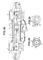
- Fig. 1 illustrates a driving shaft according to the invention comprising an inner tube 1 and an outer tube 2 having a modified cross-section in the form of a butterfly, which are axially movable but not rotatable relative to each other for transmitting torque through these tubes 1 and 2.
- the driving shaft 3 further comprises two universal joints 4 provided at the ends and safety covers 5 in the form of bellows surrounding the universal joints 4, respectively.
- the inner and outer tubes 1 and 2 are covered by safety cover tubes 6 and have proximal ends fixed to fitting yokes 7 of the universal joints 4, respectively.
- a plastic container 8 as partition means having a cross-section of a similar figure to that of the inner tube.
- the plastic container 8 includes a pair of partition walls 8a and 8b situated on the sides of the proximal and distal ends of the tube 1, respectively, for hermetically sealing the inside of the inner tube 1 and a hose fitting 8c having an oil hole 9 provided on the partition wall 8a on the side of the proximal end.
- the hose fitting 8c as hose mounting portion is formed on the partition wall 8a on the side of the proximal end so as to extend toward the proximal end to ensure the fixation of a hose to the hose fitting 8c by press-fitting.
- a hose 11 as oiling conduit means serves to connect a nipple 10 as oiling port means provided at the fitting yoke 7 on the side of the proximal end of the inner tube 1 and the hose fitting 8c extending toward the proximal end from the partition wall 8a of the plastic container wall 8 or partition wall means.
- the hose 11 may be made of, for example, a plastic material, copper or steel.
- the inclined portions 12 of four recessed parts participate in the torque transmission at the sliding surfaces of the inner and outer tubes 1 and 2.
- distribution passage means is provided which comprises a plurality of elongated grooves 13 (Fig. 2c) extending in the longitudinal direction of the container 8 and formed in its side walls corresponding to the portions participating in the torque transmission, and a plurality of through-holes 14 formed in the inner tube 1 so as to communicate with the elongated grooves 13.
- the container 8 may be formed so as to be slightly tapered in its longitudinal direction, thereby facilitating to fit it into the inner tube 1 by press-fitting and preventing it from being dislodged from the inner tube 1.
- the container 8 may be provided with at least one annular protrusion, four protrusions in the shown embodiment, on its outer circumference for more ensuring the fixation of the container into the inner tube 1 by press-fitting.
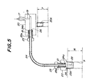
- Fig. 3 illustrates another embodiment of the driving shaft according to the invention.
- partition wall means is constructed by a pair of partition walls 16 press-fitted in the inner tube 1, and distribution passage means is composed of a plurality of through-holes 14 formed in the inner tube 1 at the locations corresponding to the portions participating in the torque transmission.
- partition walls are preferably made of a plastic material with low cost, but they may be made of a copper alloy or aluminum alloy.
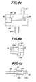
- oiling port means is composed of an inlet side hose support 20 adapted to be fixed to the fitting yoke 7 supporting the proximal end of the inner tube 1 as shown in Fig. 5.
- the inlet side hose support 20 is formed with an oiling protrusion 17, a hose receiving recess 18, and an oiling passage 19 communicating the protrusion 17 with the recess 18 as shown in Fig. 4a.
- the inlet side hose support 20 is further formed with a mounting portion 20A having external threads which are to be screwed into the fitting yoke 7 (Fig. 5).
- the inlet side hose support 20 may be made of brass, aluminum alloy or steel.
- the hose mounting portion of partition wall means is composed of an outlet side hose support 23 adapted to be fixed to the partition wall 16 on the side of the proximal end as shown in Fig. 5.
- the outlet side hose support 23 is formed with a hose receiving recess 21 and an oiling passage 22 communicating the recess 21 with the grease reserving space 8A as shown in Fig. 4b.
- the outlet side hose support 23 is further formed with an anchoring portion 23A having external threads which are to be screwed into the partition wall 16 on the side of the proximal end (Fig. 5), thereby communicating the oiling passage 22 with the oil hole 9 of the partition wall 16.
- the outlet side hose support 23 may be made of brass, aluminum alloy or steel.
- the oiling conduit means is composed of a hose 24 having radially extending flanges 24a at its both ends which are adapted to be inserted into the hose receiving recesses 18 and 21 of the inlet and outlet side hose supports 20 and 23, respectively, and hose fixing plugs 25 adapted to be fixed into the hose receiving recesses 18 and 21 of the inlet and outlet side hose supports 20 and 23 for anchoring both the ends of the hose 24 in the hose receiving recesses 18 and 21, respectively as shown in Figs. 4c and 5.
- the hose receiving recesses 18 and 21 are formed with internal threads 18A and 21A, and the hose fixing plugs 25 are formed with external threads 25A so that the hose fixing plugs 25 can be fixed in the hose receiving recesses 18 and 21 by threaded engagements.
- the inner diameter of the hose 24 is substantially equal to the diameters of the oiling passages 19 and 22.
- the hose fixing plug 25 is further formed with a hose passing hole 25a through which the hose 24 extends.
- the hose 24 includes at each end the flange 24a adapted to engage the end face of the distal end of the hose fixing plug 25 to prevent it from being removed from the hose 24. This will be achieved in a manner that a pair of hoses each having a flange 24a only at one end are inserted into the respective hose fixing plugs 25, and thereafter the other ends of these hoses having no flange are connected to each other.
- the flanges 24a of the hose 24 thus combined with the hose fixing plugs 25 are inserted into the hose receiving recesses 18 and 21 of the inlet and outlet side hose supports 20 and 23 and the hose fixing plugs 25 are then screwed into the hose receiving recesses 18 and 21 until the flanges 24a are forced into tight contact with the bottoms of the hose receiving recesses 18 and 21, thereby securely preventing the hose 24 from coming out of the hose supports 20 and 23.
- annular protrusion 26 is provided on the end surface of each of flanges 24a at both the ends of the hose 24, while an annular recess 27 adapted to engage to the annular protrusion 26 is correspondingly provided on each of the bottom surfaces of the hose receiving recesses 18 and 21 of the respective hose supports 20 and 23, thereby improving the sealing among the hose 24, the oiling passages 19 and 22 and hose fixing plugs 25.
- annular protrusion 26 instead of the annular protrusion 26 on the end surface of the flange at the end of the hose 24, an annular recess may be provided in the end surface of the flange, while an annular protrusion may be correspondingly provided on the bottom of the hose receiving recess of the hose support.
- tubes 1 and 2 in the form of the butterfly as those of the modified cross-section are shown in the above embodiments, it is to be understood that without limiting it to the butterfly any other shapes of modified cross-section may be applicable to the invention, for example, as a lemon or star-shaped cross-section.
- grease is filled through a hose in the grease reserving space defined by the container 8 in the embodiment shown in Figs. 1 and 2 or by the partition walls 16 in the embodiment shown in Fig. 3.
- the amount of the grease reserved in the grease reserving space is sufficient to supply the grease to the portions participating in the torque transmission in a stable and durable manner through the distribution passage means, thereby ensuring the complete lubrication of the portions participating in the torque transmission for a long period of time without requiring frequent replenishment of grease.
- the lubrication on the torque transmission portions accomplished by the invention reduces the thrust or frictional resistance and noise when the driving shaft is rotating and considerably prolongs the service life of the tubes of the modified cross-section.
- the hose mounting portion formed as an elongated projection enabling the hose to be fixed thereto by press-fitting in the embodiment shown in Figs. 1 and 2, or with the hose mounting portion composed of the outlet side hose support 23 and further the inlet side hose support 20, the flanged hose 24 and the hose fixing plugs 25 associated therewith in the embodiment shown in Fig. 3, the hose is surely prevented from being unintentionally removed from that portion. Furthermore, with the mutually engageable annular protrusions and recesses formed on the end surfaces of the hose flanges and bottom surfaces of the hose receiving recesses of hose supports, the tightness in sealing is improved.
Landscapes
- Engineering & Computer Science (AREA)
- General Engineering & Computer Science (AREA)
- Mechanical Engineering (AREA)
- Life Sciences & Earth Sciences (AREA)
- Ocean & Marine Engineering (AREA)
- Soil Sciences (AREA)
- Environmental Sciences (AREA)
- Manufacturing & Machinery (AREA)
- General Details Of Gearings (AREA)
- Loading And Unloading Of Fuel Tanks Or Ships (AREA)
Applications Claiming Priority (3)
| Application Number | Priority Date | Filing Date | Title |
|---|---|---|---|
| JP31718597A JP3353030B2 (ja) | 1997-11-18 | 1997-11-18 | 駆動軸 |
| JP317185/97 | 1997-11-18 | ||
| JP31718597 | 1997-11-18 |
Publications (3)
| Publication Number | Publication Date |
|---|---|
| EP0916856A2 true EP0916856A2 (de) | 1999-05-19 |
| EP0916856A3 EP0916856A3 (de) | 2000-05-10 |
| EP0916856B1 EP0916856B1 (de) | 2003-05-21 |
Family
ID=18085411
Family Applications (1)
| Application Number | Title | Priority Date | Filing Date |
|---|---|---|---|
| EP98203840A Expired - Lifetime EP0916856B1 (de) | 1997-11-18 | 1998-11-13 | Antriebswelle |
Country Status (8)
| Country | Link |
|---|---|
| US (1) | US6217455B1 (de) |
| EP (1) | EP0916856B1 (de) |
| JP (1) | JP3353030B2 (de) |
| KR (1) | KR100289524B1 (de) |
| CN (1) | CN1136398C (de) |
| DE (1) | DE69814796T2 (de) |
| ES (1) | ES2200267T3 (de) |
| TW (1) | TW405017B (de) |
Cited By (1)
| Publication number | Priority date | Publication date | Assignee | Title |
|---|---|---|---|---|
| US6217455B1 (en) * | 1997-11-18 | 2001-04-17 | Matsui-Walterscheid Ltd. | Driving shaft |
Families Citing this family (12)
| Publication number | Priority date | Publication date | Assignee | Title |
|---|---|---|---|---|
| SE515313C2 (sv) * | 1999-10-01 | 2001-07-09 | Volvo Articulated Haulers Ab | Förlängningsanordning för motorfordon |
| KR100780718B1 (ko) | 2004-12-28 | 2007-12-26 | 엘지.필립스 엘시디 주식회사 | 도포액 공급장치를 구비한 슬릿코터 |
| US7370918B2 (en) * | 2005-05-31 | 2008-05-13 | Tucker Sno-Cat Corporation | Wheel assembly for a tracked vehicle and anti-accumulation sleeve therefor |
| US9643266B1 (en) | 2006-10-27 | 2017-05-09 | Battenfeld Technologies, Inc. | Extendable folding saw |
| KR20110045096A (ko) * | 2008-09-12 | 2011-05-03 | 게케엔 드리펠린 인터나쇼날 게엠베하 | 적어도 두개의 원주방향의 외측 리브를 가진 부착 구역을 포함하는 부트 |
| JP5516157B2 (ja) * | 2010-07-06 | 2014-06-11 | 株式会社ジェイテクト | 動力伝達軸装置 |
| RU2494373C1 (ru) * | 2012-03-20 | 2013-09-27 | Российская академия наук Федеральное государственное бюджетное учреждение науки Институт систем обработки изображений Российской академии наук (ИСОИ РАН) | Способ определения оптических параметров кристаллического вещества |
| TWI558929B (zh) * | 2014-09-02 | 2016-11-21 | 應用奈米科技股份有限公司 | 可擺動及位移之密封軸承組件 |
| CN105953063A (zh) * | 2016-06-13 | 2016-09-21 | 耐世特凌云驱动系统(芜湖)有限公司 | 驱动轴自动注油装置 |
| CN108180229A (zh) * | 2017-12-29 | 2018-06-19 | 北京汽车研究总院有限公司 | 一种传动轴、传动系统及车辆 |
| KR102067649B1 (ko) * | 2018-01-22 | 2020-01-17 | 이래에이엠에스 주식회사 | 드라이브 샤프트의 플런징 어셈블리 |
| CN114060306A (zh) * | 2021-11-30 | 2022-02-18 | 厦门水务集团有限公司 | 一种低扰动的双基础立式水泵机组 |
Citations (1)
| Publication number | Priority date | Publication date | Assignee | Title |
|---|---|---|---|---|
| JPH05312219A (ja) | 1992-05-12 | 1993-11-22 | Matsui Warutaashiyaido Kk | 駆動軸 |
Family Cites Families (8)
| Publication number | Priority date | Publication date | Assignee | Title |
|---|---|---|---|---|
| US3105370A (en) * | 1961-04-18 | 1963-10-01 | Anthony V Weasler | Lubrication of the relatively extensible parts of a telescopic shaft |
| IT1241741B (it) * | 1990-06-22 | 1994-02-01 | Edi Bondioli | Protezione per alberi cardanici con mezzi per la lubrificazione |
| DE4237176C1 (de) * | 1992-11-04 | 1994-06-01 | Walterscheid Gmbh Gkn | Schmiervorrichtung für zwei ineinander verschiebbare Schiebeprofile, insbesondere einer Gelenkwelle |
| NL194319C (nl) * | 1993-09-16 | 2002-01-04 | Walterscheid Gmbh Gkn | Lengtecompensatiedeel met twee profielen voor aandrijfassen. |
| JP3585984B2 (ja) * | 1995-03-20 | 2004-11-10 | 株式会社松井製作所 | 駆動軸 |
| JPH08254216A (ja) * | 1995-03-20 | 1996-10-01 | Matsui Seisakusho:Kk | 軸継手 |
| DE19712158C2 (de) * | 1997-03-22 | 2000-06-08 | Walterscheid Gmbh Gkn | Schmiervorrichtung zum Schmieren der Profilrohre einer Teleskopwelle |
| JP3353030B2 (ja) * | 1997-11-18 | 2002-12-03 | 松井ワルターシャイド株式会社 | 駆動軸 |
-
1997
- 1997-11-18 JP JP31718597A patent/JP3353030B2/ja not_active Expired - Fee Related
-
1998
- 1998-11-10 TW TW087118699A patent/TW405017B/zh active
- 1998-11-13 EP EP98203840A patent/EP0916856B1/de not_active Expired - Lifetime
- 1998-11-13 DE DE69814796T patent/DE69814796T2/de not_active Expired - Lifetime
- 1998-11-13 US US09/191,792 patent/US6217455B1/en not_active Expired - Lifetime
- 1998-11-13 ES ES98203840T patent/ES2200267T3/es not_active Expired - Lifetime
- 1998-11-17 KR KR1019980049180A patent/KR100289524B1/ko not_active Expired - Lifetime
- 1998-11-18 CN CNB98124789XA patent/CN1136398C/zh not_active Expired - Lifetime
Patent Citations (1)
| Publication number | Priority date | Publication date | Assignee | Title |
|---|---|---|---|---|
| JPH05312219A (ja) | 1992-05-12 | 1993-11-22 | Matsui Warutaashiyaido Kk | 駆動軸 |
Cited By (1)
| Publication number | Priority date | Publication date | Assignee | Title |
|---|---|---|---|---|
| US6217455B1 (en) * | 1997-11-18 | 2001-04-17 | Matsui-Walterscheid Ltd. | Driving shaft |
Also Published As
| Publication number | Publication date |
|---|---|
| ES2200267T3 (es) | 2004-03-01 |
| JP3353030B2 (ja) | 2002-12-03 |
| DE69814796T2 (de) | 2004-03-18 |
| KR100289524B1 (ko) | 2001-05-02 |
| KR19990045332A (ko) | 1999-06-25 |
| EP0916856B1 (de) | 2003-05-21 |
| CN1136398C (zh) | 2004-01-28 |
| JPH11153149A (ja) | 1999-06-08 |
| TW405017B (en) | 2000-09-11 |
| US6217455B1 (en) | 2001-04-17 |
| CN1218149A (zh) | 1999-06-02 |
| DE69814796D1 (de) | 2003-06-26 |
| EP0916856A3 (de) | 2000-05-10 |
Similar Documents
| Publication | Publication Date | Title |
|---|---|---|
| US6217455B1 (en) | Driving shaft | |
| US6099046A (en) | Connector for metal ribbed pipe | |
| KR940006956Y1 (ko) | 세경 배관 접속용 커넥터 | |
| US5492418A (en) | Intermediate bearing for multi-component drivelines in motor vehicles | |
| JPH0542595B2 (de) | ||
| US5173082A (en) | Telescopic protective casing for a transmission shaft with lubrication distribution system | |
| US4501511A (en) | Ball type universal joint and method of manufacture | |
| EP0703397B1 (de) | Verbindungskupplung für ein Wellrohr | |
| US20060189396A1 (en) | Driveline assembly with integrated joint and method of making the same | |
| US4645369A (en) | Ball type universal joint and method of manufacture | |
| GB2265688A (en) | Self-locking metal cap, for a universal joint, with a plastic bearing and lip seal | |
| JP4081165B2 (ja) | 樹脂パイプ用継手 | |
| US6250691B1 (en) | Tube/casting connector assembly | |
| US5626519A (en) | Bearing retainer with bearing retaining projection | |
| AU657229B2 (en) | Universal joint lubricant retainer | |
| US4496333A (en) | Low friction power takeoff shaft | |
| CA1209614A (en) | Pipe line coupling | |
| KR100498215B1 (ko) | 자동차의 기어변속케이블용 소켓 | |
| RU2149288C1 (ru) | Сферический шарнир | |
| JP3452996B2 (ja) | グリースニップル | |
| JPH0743060B2 (ja) | 管の受口部構造 | |
| JPH08254217A (ja) | 駆動軸 | |
| US20120020724A1 (en) | Ball joint | |
| JPS6122578Y2 (de) | ||
| JP3045760U (ja) | 流体用ホース回動継手 |
Legal Events
| Date | Code | Title | Description |
|---|---|---|---|
| PUAI | Public reference made under article 153(3) epc to a published international application that has entered the european phase |
Free format text: ORIGINAL CODE: 0009012 |
|
| AK | Designated contracting states |
Kind code of ref document: A2 Designated state(s): DE ES IT |
|
| AX | Request for extension of the european patent |
Free format text: AL;LT;LV;MK;RO;SI |
|
| PUAL | Search report despatched |
Free format text: ORIGINAL CODE: 0009013 |
|
| AK | Designated contracting states |
Kind code of ref document: A3 Designated state(s): AT BE CH CY DE DK ES FI FR GB GR IE IT LI LU MC NL PT SE |
|
| AX | Request for extension of the european patent |
Free format text: AL;LT;LV;MK;RO;SI |
|
| RIC1 | Information provided on ipc code assigned before grant |
Free format text: 7F 16C 3/03 A, 7F 16D 3/06 B |
|
| 17P | Request for examination filed |
Effective date: 20000927 |
|
| AKX | Designation fees paid |
Free format text: DE ES IT |
|
| 17Q | First examination report despatched |
Effective date: 20020507 |
|
| GRAH | Despatch of communication of intention to grant a patent |
Free format text: ORIGINAL CODE: EPIDOS IGRA |
|
| GRAH | Despatch of communication of intention to grant a patent |
Free format text: ORIGINAL CODE: EPIDOS IGRA |
|
| GRAA | (expected) grant |
Free format text: ORIGINAL CODE: 0009210 |
|
| AK | Designated contracting states |
Designated state(s): DE ES IT |
|
| REF | Corresponds to: |
Ref document number: 69814796 Country of ref document: DE Date of ref document: 20030626 Kind code of ref document: P |
|
| REG | Reference to a national code |
Ref country code: ES Ref legal event code: FG2A Ref document number: 2200267 Country of ref document: ES Kind code of ref document: T3 |
|
| PLBE | No opposition filed within time limit |
Free format text: ORIGINAL CODE: 0009261 |
|
| STAA | Information on the status of an ep patent application or granted ep patent |
Free format text: STATUS: NO OPPOSITION FILED WITHIN TIME LIMIT |
|
| 26N | No opposition filed |
Effective date: 20040224 |
|
| PGFP | Annual fee paid to national office [announced via postgrant information from national office to epo] |
Ref country code: DE Payment date: 20171214 Year of fee payment: 20 |
|
| PGFP | Annual fee paid to national office [announced via postgrant information from national office to epo] |
Ref country code: IT Payment date: 20171123 Year of fee payment: 20 Ref country code: ES Payment date: 20171211 Year of fee payment: 20 |
|
| REG | Reference to a national code |
Ref country code: DE Ref legal event code: R071 Ref document number: 69814796 Country of ref document: DE |
|
| REG | Reference to a national code |
Ref country code: ES Ref legal event code: FD2A Effective date: 20210111 |
|
| PG25 | Lapsed in a contracting state [announced via postgrant information from national office to epo] |
Ref country code: ES Free format text: LAPSE BECAUSE OF EXPIRATION OF PROTECTION Effective date: 20181114 |