EP0916153B1 - Vorrichtung zur erzeugung von plasma - Google Patents
Vorrichtung zur erzeugung von plasma Download PDFInfo
- Publication number
- EP0916153B1 EP0916153B1 EP98925635A EP98925635A EP0916153B1 EP 0916153 B1 EP0916153 B1 EP 0916153B1 EP 98925635 A EP98925635 A EP 98925635A EP 98925635 A EP98925635 A EP 98925635A EP 0916153 B1 EP0916153 B1 EP 0916153B1
- Authority
- EP
- European Patent Office
- Prior art keywords
- tube
- conductor
- plasma
- vacuum chamber
- electromagnetic alternating
- Prior art date
- Legal status (The legal status is an assumption and is not a legal conclusion. Google has not performed a legal analysis and makes no representation as to the accuracy of the status listed.)
- Expired - Lifetime
Links
- 239000004020 conductor Substances 0.000 claims description 45
- 239000011810 insulating material Substances 0.000 claims description 3
- 210000002381 plasma Anatomy 0.000 description 35
- 238000000034 method Methods 0.000 description 12
- 238000009826 distribution Methods 0.000 description 6
- 239000011521 glass Substances 0.000 description 6
- 239000002184 metal Substances 0.000 description 5
- 230000007704 transition Effects 0.000 description 4
- 244000089486 Phragmites australis subsp australis Species 0.000 description 3
- 238000013016 damping Methods 0.000 description 3
- 230000005672 electromagnetic field Effects 0.000 description 3
- 230000015572 biosynthetic process Effects 0.000 description 2
- 239000011248 coating agent Substances 0.000 description 2
- 238000000576 coating method Methods 0.000 description 2
- 230000035515 penetration Effects 0.000 description 2
- 230000007423 decrease Effects 0.000 description 1
- 230000008021 deposition Effects 0.000 description 1
- 229910003460 diamond Inorganic materials 0.000 description 1
- 239000010432 diamond Substances 0.000 description 1
- 230000002500 effect on skin Effects 0.000 description 1
- 230000000694 effects Effects 0.000 description 1
- 230000005684 electric field Effects 0.000 description 1
- 238000005516 engineering process Methods 0.000 description 1
- 230000002787 reinforcement Effects 0.000 description 1
- 239000000126 substance Substances 0.000 description 1
- 238000004381 surface treatment Methods 0.000 description 1
- 238000009827 uniform distribution Methods 0.000 description 1
Images



Classifications
-
- H—ELECTRICITY
- H01—ELECTRIC ELEMENTS
- H01J—ELECTRIC DISCHARGE TUBES OR DISCHARGE LAMPS
- H01J37/00—Discharge tubes with provision for introducing objects or material to be exposed to the discharge, e.g. for the purpose of examination or processing thereof
- H01J37/32—Gas-filled discharge tubes
- H01J37/32009—Arrangements for generation of plasma specially adapted for examination or treatment of objects, e.g. plasma sources
- H01J37/32192—Microwave generated discharge
- H01J37/32211—Means for coupling power to the plasma
- H01J37/3222—Antennas
-
- H—ELECTRICITY
- H05—ELECTRIC TECHNIQUES NOT OTHERWISE PROVIDED FOR
- H05H—PLASMA TECHNIQUE; PRODUCTION OF ACCELERATED ELECTRICALLY-CHARGED PARTICLES OR OF NEUTRONS; PRODUCTION OR ACCELERATION OF NEUTRAL MOLECULAR OR ATOMIC BEAMS
- H05H1/00—Generating plasma; Handling plasma
- H05H1/24—Generating plasma
- H05H1/26—Plasma torches
-
- H—ELECTRICITY
- H01—ELECTRIC ELEMENTS
- H01J—ELECTRIC DISCHARGE TUBES OR DISCHARGE LAMPS
- H01J37/00—Discharge tubes with provision for introducing objects or material to be exposed to the discharge, e.g. for the purpose of examination or processing thereof
- H01J37/32—Gas-filled discharge tubes
- H01J37/32009—Arrangements for generation of plasma specially adapted for examination or treatment of objects, e.g. plasma sources
- H01J37/32192—Microwave generated discharge
-
- H—ELECTRICITY
- H05—ELECTRIC TECHNIQUES NOT OTHERWISE PROVIDED FOR
- H05H—PLASMA TECHNIQUE; PRODUCTION OF ACCELERATED ELECTRICALLY-CHARGED PARTICLES OR OF NEUTRONS; PRODUCTION OR ACCELERATION OF NEUTRAL MOLECULAR OR ATOMIC BEAMS
- H05H1/00—Generating plasma; Handling plasma
- H05H1/24—Generating plasma
- H05H1/46—Generating plasma using applied electromagnetic fields, e.g. high frequency or microwave energy
Definitions
- the invention relates to a device for generating plasma in a vacuum chamber with the help of electromagnetic Alternating fields, with a rod-shaped conductor within a Pipe made of insulating material through the vacuum chamber and the inner diameter of the insulating tube is larger than is the diameter of the conductor, the insulating tube to the both ends held in walls of the vacuum chamber and opposite the walls on its outer surface is sealed and the conductor at both ends to a first source for generating the electromagnetic alternating fields is connected.
- a known device for generating plasma (DE 195 03 205) makes it possible in a limited operating range (Process area, gas pressure, microwave power) plasmas for To produce surface treatments and coating technology.
- the known device consists essentially of a a cylindrical glass tube installed in a vacuum process chamber and a metallic conductive tube therein, wherein Atmospheric pressure prevails in the interior of the glass tube.
- microwave power is on both sides by two inlets and two metallic coaxial lines, consisting of inner conductor and outer conductor, introduced through the walls of the vacuum process chamber.
- the missing outer conductor of the coaxial line within the vacuum process chamber is replaced by a plasma discharge, which at sufficient ignition conditions (gas pressure) due to the microwave power is ignited and maintained, the microwave power from the two metallic coaxial lines and can exit through the glass tube into the vacuum process chamber.
- the plasma surrounds the cylindrical glass tube from the outside and forms a coaxial line with the inner conductor very high damping coating.
- Microwave power can be the gas pressure of the vacuum process chamber be adjusted so that the plasma is evident burns evenly along the device where inside the vacuum process chamber of the outer conductor of the coaxial line is missing.
- the attenuation of the microwaves does not depend in any way on the position along the coaxial line. Since the dielectric filling of the coaxial line consists of air and ⁇ R is constant over the length of the device, the amount of attenuation depends only on the depth of penetration of the microwaves into the conductive surfaces. With constant damping per unit length, this means that the net microwave power delivered to the plasma per unit length decreases along the device towards the center. Since the outer conductor consists of plasma, this conductivity cannot be determined exactly. It certainly depends on the plasma density, which in turn is within certain limits a function of the microwave power density in the discharge area. It is probably several orders of magnitude higher than that of metallic surfaces ( ⁇ 50 ⁇ m) and not constant over the length of the device.
- the known device is hardly able to maintain a plasma discharge at pressures lower than 8 ⁇ 10 -2 mbar.
- the present invention is based on the object To improve disadvantages of the known device.
- rod-shaped Ladder in the area of both wall bushings in Towards its middle section from a piece of pipe electrically conductive material is enclosed spaced, wherein the two pipe sections are arranged concentrically to the insulating pipe and each to a second source for generating an electromagnetic AC field are connected.
- the rod-shaped conductor spaced from a tube of electrically conductive material enclosed, both ends of the tube each to a second Source for generating an alternating electromagnetic field are connected, and being the middle section of the pipe with a recess, for example an elongated, rhombus-shaped Longitudinal slot is provided.
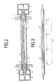
- the embodiment according to FIG. 2 differs from that previously described in that the rod-shaped conductor 4 of a spaced single pipe 20 made of electrically conductive material is enclosed, both ends of the tube 20 each are connected to a second source 14 and 15 and the middle part of the tube 20 with a longitudinal slot Recess 21 is provided.
- the device according to FIG. 1 has a total of four coaxial Microwave feeds equipped. Additional, metallic Conductive tubes 12 and 13 together with the inner conductor 4 and the outer conductors 16, 17 a total of four coaxial, concentric Microwave feeds, namely 16.12 in the range of A, 12.4 in the range of B, 13.4 in the range of C and 17.13 in the range by D.
- coaxial microwave feeds can for longer plasma sources and / or at higher gas pressures in the vacuum process chamber also six, eight or more (depending on technical feasibility) microwave feeds be installed with the distances (e.g. A-B or B-C) can be varied with each other, so that a uniform Plasma distribution is achieved.
- coaxial lines are only three metallically conductive Pipes used.
- the outer conductor of an inner coaxial line is also the inner conductor of an outer, the inner coaxial line enclosing coaxial line.
- the transition from a metallic outer conductor to one Plasma conductors can also be of a different shape, e.g. B. by coaxial Slots with increasing width. It is only essential that the transition is not shaped abruptly, but steadily and that no wave reflections occur.
- the field strength of the electrical part of the electromagnetic To increase alternating field at a given microwave power.
- the Known device (DE 195 03 205) is a traveling field structure and is using purely transverse electromagnetic (TEM) Waves operated. Nevertheless, field reinforcement can also be used in this case can be achieved by the cross section of the metallic Inner conductor 4 from the cylindrical shape (Fig. 4) to one edgy shape (Fig. 5) is changed.
- FIG. 1 causes a more uniform Distribution of the field strength of the electrical part of the electromagnetic Alternating field of microwaves over the entire Length of the device, as indicated in Fig. 6.
- At only Two feed points A, D result in a distribution according to the curve L, with four feed points is a distribution expected according to curve M.
- the curves shown are in no absolute connection, only the courses are relevant.
- the improvement offers the opportunity the microwave power of a number greater than two Feed microwave generators into a single device. For example, this is very important for plasma chemicals Processes with process pressures of 50 mbar and higher (e.g. Diamond deposition).
- the embodiment according to FIG. 2 also produces a more uniform one Distribution of the field strength of the electrical part of the electromagnetic alternating field of the microwaves over the entire Length of the device, as indicated in Fig. 7. at the steadily increasing transition from a metallic coaxial line into a plasma line between points E-F and G-H there is a distribution according to curve O.
- Curve O already represents almost the ideal distribution for linear Plasma sources. This improvement works like the original one Device with only two feed points.
- the device can be absolutely homogeneous in this way Plasma densities can be achieved over longer distances (e.g. 3 m).
Landscapes
- Physics & Mathematics (AREA)
- Engineering & Computer Science (AREA)
- Plasma & Fusion (AREA)
- Chemical & Material Sciences (AREA)
- Analytical Chemistry (AREA)
- Spectroscopy & Molecular Physics (AREA)
- Electromagnetism (AREA)
- Plasma Technology (AREA)
Description

- a und b
- werden Außendurchmesser vom Innenleiter und Innendurchmesser vom Außenleiter einer Koaxialleitung bezeichnet,
- δS
- ist die Eindringtiefe (Skin Effekt) der Mikrowellen in die leitfähigen Oberflächen,
- λ0
- ist die Freiraumwellenlänge der verwendeten Mikrowellen und
- εR
- die relative Dielektrizitätskonstante des Dielektrikums der Koaxialleitung (= 1 für Luft).
- Fig. 1
- eine Vorrichtung zur Erzeugung von Plasma im Längsschnitt und jeweils mit Rohrstücken im Bereich der beiden Enden eines stabförmigen Leiters,
- Fig. 2
- eine alternative Ausführungsform mit einem den stabförmigen Leiter in seiner gesamten Länge umschließenden Rohr, wobei das Rohr über einen wesentlichen Teil seiner Länge mit einer längsschlitzförmigen Ausnehmung versehen ist,
- Fig. 3
- das Rohr gemäß Fig. 2,
- Fig. 4,5
- den stabförmigen Leiter in zwei Ausführungsformen und jeweils im Querschnitt dargestellt und
- Fig. 6,7
- diagrammartige Darstellungen der Feldstärke des elektromagnetischen Feldes für die in den Fig. 1 und 2 gezeigten Vorrichtungen.
- 3
- Vakuumkammer
- 4
- stabförmiger Leiter
- 5
- Isolierrohr
- 6
- Vakuumkammerwand
- 7
- Vakuumkammerwand
- 8
- erste Quelle
- 9
- erste Quelle
- 10
- Wanddurchführung
- 11
- Wanddurchführung
- 12
- Rohrstück
- 13
- Rohrstück
- 14
- zweite Quelle
- 15
- zweite Quelle
- 16
- Rohrstück, Metallmanschette
- 17
- Rohrstück, Metallmanschette
- 18
- keilförmiger Ausnehmungsabschnitt
- 19
- keilförmiger Ausnehmungsabschnitt
- 20
- Rohr
- 21
- Ausnehmung
Claims (2)
- Vorrichtung zur Erzeugung von Plasma in einer Vakuumkammer (3) mit Hilfe von elektromagnetischen Wechselfeldern, wobei ein stabförmiger Leiter (4) innerhalb eines Rohres (5) aus isolierendem Werkstoff durch die Vakuumkammer (3) geführt ist und der Innendurchmesser des Isolierrohres (5) größer als der Durchmesser des Leiters (4) ist, wobei das Isolierrohr (5) an beiden Enden in Wänden (6,7) der Vakuumkammer (3) gehalten und gegenüber den Wänden (6,7) an seiner Außenfläche abgedichtet ist und der Leiter (4) an beiden Enden jeweils an einer erste Quelle (8 bzw. 9) zur Erzeugung der elektromagnetischen Wechselfelder angeschlossen ist, dadurch gekennzeichnet, daß der stabförmige Leiter (4) jeweils im Bereich beider Wanddurchführungen (10,11) in Richtung auf seine mittlere Partie (k) zu ein Stück weit von einem Rohrstück (12,13) aus elektrisch leitendem Werkstoff beabstandet umschlossen ist, wobei die beiden Rohrstücke (12,13) konzentrisch zum Isolierrohr (5) angeordnet und jeweils die kreisringzylinderförmigen, vom Isolierrohr (5) und dem jeweiligen Rohrstück (12,13) gebildeten Zwischenräume an eine zweite Quelle (14 bzw. 15) zur Erzeugung eines elektromagnetischen Wechselfeldes angeschlossen sind.
- Vorrichtung zur Erzeugung von Plasma in einer Vakuumkammer (3) mit Hilfe von elektromagnetischen Wechselfeldern, wobei ein stabförmiger Leiter (4) innerhalb eines Rohres (5) aus isolierendem Werkstoff durch die Vakuumkammer (3) geführt ist und der Innendurchmesser des Isolierrohres (5) größer als der Durchmesser des Leiters (4) ist, wobei das Isolierrohr (5) an beiden Enden in Wänden (6,7) der Vakuumkammer (3) gehalten und gegenüber den Wänden (6,7) an seiner Außenfläche abgedichtet ist und der Leiter (4) an beiden Enden jeweils an einer erste Quelle (8 bzw. 9) zur Erzeugung der elektromagnetischen Wechselfelder angeschlossen ist, dadurch gekennzeichnet, daß der stabförmige Leiter (4) von einem Rohr (209 aus elektrisch leitendem Werkstoff beabstandet umschlossen ist und beide Enden des Rohrs (20) jeweils an eine zweite Quelle (14 bzw. 15) zur Erzeugung eines elektromagnetischen Wechselfeldes angeschlossen sind, wobei die mittlere Partie des Rohres (20) mit einer Ausnehmung (21), beispielsweise einem länglichen, rhombusförmigen Längsschlitz, versehen ist.
Applications Claiming Priority (3)
| Application Number | Priority Date | Filing Date | Title |
|---|---|---|---|
| DE19722272 | 1997-05-28 | ||
| DE19722272A DE19722272A1 (de) | 1997-05-28 | 1997-05-28 | Vorrichtung zur Erzeugung von Plasma |
| PCT/EP1998/003062 WO1998054748A1 (de) | 1997-05-28 | 1998-05-25 | Vorrichtung zur erzeugung von plasma |
Publications (2)
| Publication Number | Publication Date |
|---|---|
| EP0916153A1 EP0916153A1 (de) | 1999-05-19 |
| EP0916153B1 true EP0916153B1 (de) | 2003-11-05 |
Family
ID=7830698
Family Applications (1)
| Application Number | Title | Priority Date | Filing Date |
|---|---|---|---|
| EP98925635A Expired - Lifetime EP0916153B1 (de) | 1997-05-28 | 1998-05-25 | Vorrichtung zur erzeugung von plasma |
Country Status (6)
| Country | Link |
|---|---|
| US (1) | US6194835B1 (de) |
| EP (1) | EP0916153B1 (de) |
| JP (1) | JP3853377B2 (de) |
| KR (1) | KR100284903B1 (de) |
| DE (2) | DE19722272A1 (de) |
| WO (1) | WO1998054748A1 (de) |
Families Citing this family (25)
| Publication number | Priority date | Publication date | Assignee | Title |
|---|---|---|---|---|
| DE19812558B4 (de) * | 1998-03-21 | 2010-09-23 | Roth & Rau Ag | Vorrichtung zur Erzeugung linear ausgedehnter ECR-Plasmen |
| DE19841777C1 (de) * | 1998-09-12 | 2000-01-05 | Fraunhofer Ges Forschung | Vorrichtung zur plasmatechnischen Abscheidung von polykristallinem Diamant |
| DE19848022A1 (de) * | 1998-10-17 | 2000-04-20 | Leybold Systems Gmbh | Vorrichtung zur Erzeugung von Plasma |
| US20060191637A1 (en) * | 2001-06-21 | 2006-08-31 | John Zajac | Etching Apparatus and Process with Thickness and Uniformity Control |
| US20030185973A1 (en) * | 2002-03-30 | 2003-10-02 | Crawley Richard L. | Water vapor plasma method of increasing the surface energy of a surface |
| JP5404984B2 (ja) * | 2003-04-24 | 2014-02-05 | 東京エレクトロン株式会社 | プラズマモニタリング方法、プラズマモニタリング装置及びプラズマ処理装置 |
| US20070095281A1 (en) * | 2005-11-01 | 2007-05-03 | Stowell Michael W | System and method for power function ramping of microwave liner discharge sources |
| JP5239021B2 (ja) * | 2006-03-07 | 2013-07-17 | 国立大学法人 琉球大学 | プラズマ発生装置及びそれを用いたプラズマ生成方法 |
| DE102006012100B3 (de) * | 2006-03-16 | 2007-09-20 | Maschinenfabrik Reinhausen Gmbh | Vorrichtung zur Erzeugung eines Plasma-Jets |
| WO2008018159A1 (en) * | 2006-08-08 | 2008-02-14 | Adtec Plasma Technology Co., Ltd. | Microwave line plasma generation system with two power supply |
| DE102006048816A1 (de) * | 2006-10-16 | 2008-04-17 | Iplas Innovative Plasma Systems Gmbh | Vorrichtung und Verfahren zur lokalen Erzeugung von Mikrowellenplasmen |
| DE102006048814B4 (de) * | 2006-10-16 | 2014-01-16 | Iplas Innovative Plasma Systems Gmbh | Vorrichtung und Verfahren zur Erzeugung von Mikrowellenplasmen hoher Plasmadichte |
| DE102006048815B4 (de) * | 2006-10-16 | 2016-03-17 | Iplas Innovative Plasma Systems Gmbh | Vorrichtung und Verfahren zur Erzeugung von Mikrowellenplasmen hoher Leistung |
| EP2253008B1 (de) * | 2008-03-12 | 2017-02-01 | Alytus Corporation, S.A. | Plasma-system |
| DE102008036766B4 (de) * | 2008-08-07 | 2013-08-01 | Alexander Gschwandtner | Vorrichtung und Verfahren zum Erzeugen dielektrischer Schichten im Mikrowellenplasma |
| TW201105183A (en) * | 2009-07-21 | 2011-02-01 | Delta Electronics Inc | Plasma generating apparatus |
| KR20110020702A (ko) * | 2009-08-24 | 2011-03-03 | 한국기초과학지원연구원 | 균일한 대면적 마이크로웨이브 플라즈마 발생원을 위한 영구자석 장착형 안테나 |
| EP2517228A2 (de) | 2009-12-23 | 2012-10-31 | Wilhelm Beckmann | Verfahren und vorrichtung zum ausbilden einer dielektrischen schicht auf einem substrat |
| US9324597B2 (en) * | 2010-04-30 | 2016-04-26 | Applied Materials, Inc. | Vertical inline CVD system |
| DE102010035593B4 (de) * | 2010-08-27 | 2014-07-10 | Hq-Dielectrics Gmbh | Verfahren und Vorrichtung zum Behandeln eines Substrats mittels eines Plasmas |
| DE102011100024A1 (de) | 2011-04-29 | 2012-10-31 | Centrotherm Thermal Solutions Gmbh & Co. Kg | Verfahren zum ausbilden einer schicht auf einem substrat |
| DE102011107072B8 (de) | 2011-07-12 | 2013-01-17 | Centrotherm Thermal Solutions Gmbh & Co. Kg | Verfahren zum ausbilden einer oxidschicht auf einem substrat bei tiefen temperaturen |
| DE102012103425A1 (de) * | 2012-04-19 | 2013-10-24 | Roth & Rau Ag | Mikrowellenplasmaerzeugungsvorrichtung und Verfahren zu deren Betrieb |
| WO2018187443A2 (en) * | 2017-04-07 | 2018-10-11 | Nuionic Technologies Lp | Microwave enhancement of chemical reactions |
| JP6579587B2 (ja) * | 2017-09-20 | 2019-09-25 | 住友理工株式会社 | プラズマ処理装置 |
Family Cites Families (8)
| Publication number | Priority date | Publication date | Assignee | Title |
|---|---|---|---|---|
| DE1950327B2 (de) | 1969-09-30 | 1972-07-06 | Siemens AG, 1000 Berlin u. 8000 München | Korpuskularstrahlgeraet mit magnetischen mitteln zur querverstellung von teilen |
| US4515107A (en) * | 1982-11-12 | 1985-05-07 | Sovonics Solar Systems | Apparatus for the manufacture of photovoltaic devices |
| DE3244391A1 (de) * | 1982-12-01 | 1984-06-07 | Leybold-Heraeus GmbH, 5000 Köln | Vorrichtung zur beschichtung von substraten durch plasmapolymerisation |
| DE4136297A1 (de) * | 1991-11-04 | 1993-05-06 | Plasma Electronic Gmbh, 7024 Filderstadt, De | Vorrichtung zur lokalen erzeugung eines plasmas in einer behandlungskammer mittels mikrowellenanregung |
| EP0702393A3 (de) * | 1994-09-16 | 1997-03-26 | Daihen Corp | Plasmabearbeitungsgerät zur Mikrowellen-Einstrahlung aus einem rechteckigen Wellenleiter durch einem langgestrekten Schlitz in der Plasmakammer |
| US5523652A (en) * | 1994-09-26 | 1996-06-04 | Eaton Corporation | Microwave energized ion source for ion implantation |
| DE4445762A1 (de) * | 1994-12-21 | 1996-06-27 | Adolf Slaby Inst Forschungsges | Verfahren und Vorrichtung zum Bestimmen absoluter Plasmaparameter |
| DE19503205C1 (de) * | 1995-02-02 | 1996-07-11 | Muegge Electronic Gmbh | Vorrichtung zur Erzeugung von Plasma |
-
1997
- 1997-05-28 DE DE19722272A patent/DE19722272A1/de not_active Withdrawn
-
1998
- 1998-05-25 WO PCT/EP1998/003062 patent/WO1998054748A1/de not_active Ceased
- 1998-05-25 US US09/230,567 patent/US6194835B1/en not_active Expired - Lifetime
- 1998-05-25 JP JP50021399A patent/JP3853377B2/ja not_active Expired - Lifetime
- 1998-05-25 EP EP98925635A patent/EP0916153B1/de not_active Expired - Lifetime
- 1998-05-25 KR KR1019980710948A patent/KR100284903B1/ko not_active Expired - Lifetime
- 1998-05-25 DE DE59810077T patent/DE59810077D1/de not_active Expired - Lifetime
Also Published As
| Publication number | Publication date |
|---|---|
| WO1998054748A1 (de) | 1998-12-03 |
| DE59810077D1 (de) | 2003-12-11 |
| US6194835B1 (en) | 2001-02-27 |
| EP0916153A1 (de) | 1999-05-19 |
| DE19722272A1 (de) | 1998-12-03 |
| KR100284903B1 (ko) | 2001-03-15 |
| KR20000022504A (ko) | 2000-04-25 |
| JP3853377B2 (ja) | 2006-12-06 |
| JP2000515678A (ja) | 2000-11-21 |
Similar Documents
| Publication | Publication Date | Title |
|---|---|---|
| EP0916153A1 (de) | Vorrichtung zur erzeugung von plasma | |
| DE3234100C2 (de) | Plasmalichtbogeneinrichtung zum Auftragen von Überzügen | |
| DE19628952B4 (de) | Vorrichtung zur Erzeugung von Plasma | |
| DE2548220C2 (de) | ||
| DE4319717A1 (de) | Vorrichtung zum Erzeugen planaren Niedrigdruckplasmas unter Verwendung einer Spule mit deren Achse parallel zu der Oberfläche eines Koppelfensters | |
| DE102010027619B3 (de) | Mikrowellenplasmaquelle mit einer Vorrichtung zur Zuführung von Mikrowellenenergie | |
| EP1994807B1 (de) | Vorrichtung zur erzeugung eines plasma-jets | |
| DE102004014584B4 (de) | Hochfrequenz-Quadrupolsysteme mit Potentialgradienten | |
| EP1183709B1 (de) | Linear ausgedehnte anordnung zur grossflächigen mikrowellenbehandlung und zur grossflächigen plasmaerzeugung | |
| DE1955914A1 (de) | Hochfrequenz-Plasmagenerator | |
| DE4317964C2 (de) | Vorrichtung zur plasmachemischen Bearbeitung von Schadstoffen und Materialien | |
| EP0961528B1 (de) | Vorrichtung zur Erzeugung von Plasma | |
| EP1421832B1 (de) | Plasmabrenner mit mikrowellenanregung | |
| DD263648B5 (de) | Einrichtung zur erzeugungs eines Mikrowellenplasmas mit grosser Ausdehnung und Homogenitaet | |
| EP1252647B1 (de) | Einkoppelanordnung für mikrowellenenergie mit impedanzanpassung | |
| EP0963141A2 (de) | Vorrichtung zur Erzeugung von Plasma | |
| DE19801366A1 (de) | Vorrichtung zur Erzeugung von Plasma | |
| DE10341239B4 (de) | ECR-Plasmaquelle mit linearer Plasmaaustrittsöffnung | |
| DE69206543T2 (de) | Elektronzyklotronresonanz-Ionenquelle mit koaxialer Zuführung elektromagnetischer Wellen. | |
| EP0375840A2 (de) | Anordnung zum Übertragen von Hochfrequenzsignalen | |
| DE19848022A1 (de) | Vorrichtung zur Erzeugung von Plasma | |
| DE102006034084B4 (de) | Anordnung zur Konzentration von Mikrowellenenergie | |
| EP1709663A2 (de) | Vorrichtung zur erzeugung angeregter und/oder ionisierter teilchen in einem plasma und verfahren zur erzeugung ionisierter teilchen | |
| DE102024102647A1 (de) | Dualer plasmaapplikator für einen plasmagenerator, plasmagenerator, plasmabearbeitungsanlage und verfahren zum zünden eines plasmas | |
| EP4740264A1 (de) | Wellenleiterelement und verfahren zur herstellung eines wellenleiterelements, sowie hochfrequenzanordnung und radarsystem |
Legal Events
| Date | Code | Title | Description |
|---|---|---|---|
| PUAI | Public reference made under article 153(3) epc to a published international application that has entered the european phase |
Free format text: ORIGINAL CODE: 0009012 |
|
| 17P | Request for examination filed |
Effective date: 19981127 |
|
| AK | Designated contracting states |
Kind code of ref document: A1 Designated state(s): DE ES FR GB IT LU NL |
|
| GRAH | Despatch of communication of intention to grant a patent |
Free format text: ORIGINAL CODE: EPIDOS IGRA |
|
| RAP1 | Party data changed (applicant data changed or rights of an application transferred) |
Owner name: UNAXIS DEUTSCHLAND HOLDING GMBH |
|
| GRAS | Grant fee paid |
Free format text: ORIGINAL CODE: EPIDOSNIGR3 |
|
| GRAA | (expected) grant |
Free format text: ORIGINAL CODE: 0009210 |
|
| AK | Designated contracting states |
Kind code of ref document: B1 Designated state(s): DE ES FR GB IT LU NL |
|
| PG25 | Lapsed in a contracting state [announced via postgrant information from national office to epo] |
Ref country code: IT Free format text: LAPSE BECAUSE OF FAILURE TO SUBMIT A TRANSLATION OF THE DESCRIPTION OR TO PAY THE FEE WITHIN THE PRE;WARNING: LAPSES OF ITALIAN PATENTS WITH EFFECTIVE DATE BEFORE 2007 MAY HAVE OCCURRED AT ANY TIME BEFORE 2007. THE CORRECT EFFECTIVE DATE MAY BE DIFFERENT FROM THE ONE RECORDED.SCRIBED TIME-LIMIT Effective date: 20031105 Ref country code: GB Free format text: LAPSE BECAUSE OF FAILURE TO SUBMIT A TRANSLATION OF THE DESCRIPTION OR TO PAY THE FEE WITHIN THE PRESCRIBED TIME-LIMIT Effective date: 20031105 |
|
| REG | Reference to a national code |
Ref country code: GB Ref legal event code: FG4D Free format text: NOT ENGLISH |
|
| REF | Corresponds to: |
Ref document number: 59810077 Country of ref document: DE Date of ref document: 20031211 Kind code of ref document: P |
|
| PG25 | Lapsed in a contracting state [announced via postgrant information from national office to epo] |
Ref country code: ES Free format text: LAPSE BECAUSE OF FAILURE TO SUBMIT A TRANSLATION OF THE DESCRIPTION OR TO PAY THE FEE WITHIN THE PRESCRIBED TIME-LIMIT Effective date: 20040216 |
|
| GBV | Gb: ep patent (uk) treated as always having been void in accordance with gb section 77(7)/1977 [no translation filed] |
Effective date: 20031105 |
|
| PG25 | Lapsed in a contracting state [announced via postgrant information from national office to epo] |
Ref country code: LU Free format text: LAPSE BECAUSE OF NON-PAYMENT OF DUE FEES Effective date: 20040525 |
|
| ET | Fr: translation filed | ||
| PLBE | No opposition filed within time limit |
Free format text: ORIGINAL CODE: 0009261 |
|
| STAA | Information on the status of an ep patent application or granted ep patent |
Free format text: STATUS: NO OPPOSITION FILED WITHIN TIME LIMIT |
|
| 26N | No opposition filed |
Effective date: 20040806 |
|
| PGFP | Annual fee paid to national office [announced via postgrant information from national office to epo] |
Ref country code: FR Payment date: 20100611 Year of fee payment: 13 |
|
| PGFP | Annual fee paid to national office [announced via postgrant information from national office to epo] |
Ref country code: NL Payment date: 20100514 Year of fee payment: 13 Ref country code: DE Payment date: 20100521 Year of fee payment: 13 |
|
| REG | Reference to a national code |
Ref country code: DE Ref legal event code: R119 Ref document number: 59810077 Country of ref document: DE |
|
| REG | Reference to a national code |
Ref country code: DE Ref legal event code: R119 Ref document number: 59810077 Country of ref document: DE |
|
| REG | Reference to a national code |
Ref country code: NL Ref legal event code: V1 Effective date: 20111201 |
|
| PG25 | Lapsed in a contracting state [announced via postgrant information from national office to epo] |
Ref country code: NL Free format text: LAPSE BECAUSE OF NON-PAYMENT OF DUE FEES Effective date: 20111201 |
|
| REG | Reference to a national code |
Ref country code: FR Ref legal event code: ST Effective date: 20120131 |
|
| PG25 | Lapsed in a contracting state [announced via postgrant information from national office to epo] |
Ref country code: FR Free format text: LAPSE BECAUSE OF NON-PAYMENT OF DUE FEES Effective date: 20110531 |
|
| PG25 | Lapsed in a contracting state [announced via postgrant information from national office to epo] |
Ref country code: DE Free format text: LAPSE BECAUSE OF NON-PAYMENT OF DUE FEES Effective date: 20111130 |