EP0915775B1 - Fahrzeugsitzaufhängung mit niedriger profilkonstruktion und kombiniertem längenverstellmechanismus - Google Patents
Fahrzeugsitzaufhängung mit niedriger profilkonstruktion und kombiniertem längenverstellmechanismus Download PDFInfo
- Publication number
- EP0915775B1 EP0915775B1 EP97936200A EP97936200A EP0915775B1 EP 0915775 B1 EP0915775 B1 EP 0915775B1 EP 97936200 A EP97936200 A EP 97936200A EP 97936200 A EP97936200 A EP 97936200A EP 0915775 B1 EP0915775 B1 EP 0915775B1
- Authority
- EP
- European Patent Office
- Prior art keywords
- vehicle seat
- low profile
- seat suspension
- adjustment
- profile vehicle
- Prior art date
- Legal status (The legal status is an assumption and is not a legal conclusion. Google has not performed a legal analysis and makes no representation as to the accuracy of the status listed.)
- Expired - Lifetime
Links
- 239000000725 suspension Substances 0.000 title claims description 60
- 230000007246 mechanism Effects 0.000 title claims description 23
- 230000000712 assembly Effects 0.000 claims description 11
- 238000000429 assembly Methods 0.000 claims description 11
- 230000036316 preload Effects 0.000 claims description 10
- 230000006835 compression Effects 0.000 claims description 2
- 238000007906 compression Methods 0.000 claims description 2
- 229910000831 Steel Inorganic materials 0.000 description 2
- 239000007787 solid Substances 0.000 description 2
- 239000010959 steel Substances 0.000 description 2
- 229920004943 Delrin® Polymers 0.000 description 1
- 210000001520 comb Anatomy 0.000 description 1
- 230000000295 complement effect Effects 0.000 description 1
- 210000005069 ears Anatomy 0.000 description 1
- 230000002349 favourable effect Effects 0.000 description 1
- 238000012423 maintenance Methods 0.000 description 1
- 230000013011 mating Effects 0.000 description 1
- 230000035939 shock Effects 0.000 description 1
- 238000003466 welding Methods 0.000 description 1
Images


Classifications
-
- B—PERFORMING OPERATIONS; TRANSPORTING
- B60—VEHICLES IN GENERAL
- B60N—SEATS SPECIALLY ADAPTED FOR VEHICLES; VEHICLE PASSENGER ACCOMMODATION NOT OTHERWISE PROVIDED FOR
- B60N2/00—Seats specially adapted for vehicles; Arrangement or mounting of seats in vehicles
- B60N2/50—Seat suspension devices
- B60N2/502—Seat suspension devices attached to the base of the seat
-
- B—PERFORMING OPERATIONS; TRANSPORTING
- B60—VEHICLES IN GENERAL
- B60N—SEATS SPECIALLY ADAPTED FOR VEHICLES; VEHICLE PASSENGER ACCOMMODATION NOT OTHERWISE PROVIDED FOR
- B60N2/00—Seats specially adapted for vehicles; Arrangement or mounting of seats in vehicles
- B60N2/02—Seats specially adapted for vehicles; Arrangement or mounting of seats in vehicles the seat or part thereof being movable, e.g. adjustable
- B60N2/04—Seats specially adapted for vehicles; Arrangement or mounting of seats in vehicles the seat or part thereof being movable, e.g. adjustable the whole seat being movable
- B60N2/06—Seats specially adapted for vehicles; Arrangement or mounting of seats in vehicles the seat or part thereof being movable, e.g. adjustable the whole seat being movable slidable
- B60N2/08—Seats specially adapted for vehicles; Arrangement or mounting of seats in vehicles the seat or part thereof being movable, e.g. adjustable the whole seat being movable slidable characterised by the locking device
- B60N2/0812—Location of the latch
- B60N2/0825—Location of the latch outside the rail
-
- B—PERFORMING OPERATIONS; TRANSPORTING
- B60—VEHICLES IN GENERAL
- B60N—SEATS SPECIALLY ADAPTED FOR VEHICLES; VEHICLE PASSENGER ACCOMMODATION NOT OTHERWISE PROVIDED FOR
- B60N2/00—Seats specially adapted for vehicles; Arrangement or mounting of seats in vehicles
- B60N2/02—Seats specially adapted for vehicles; Arrangement or mounting of seats in vehicles the seat or part thereof being movable, e.g. adjustable
- B60N2/04—Seats specially adapted for vehicles; Arrangement or mounting of seats in vehicles the seat or part thereof being movable, e.g. adjustable the whole seat being movable
- B60N2/06—Seats specially adapted for vehicles; Arrangement or mounting of seats in vehicles the seat or part thereof being movable, e.g. adjustable the whole seat being movable slidable
- B60N2/08—Seats specially adapted for vehicles; Arrangement or mounting of seats in vehicles the seat or part thereof being movable, e.g. adjustable the whole seat being movable slidable characterised by the locking device
- B60N2/0831—Movement of the latch
- B60N2/0837—Movement of the latch pivoting
- B60N2/0843—Movement of the latch pivoting about a longitudinal axis
-
- B—PERFORMING OPERATIONS; TRANSPORTING
- B60—VEHICLES IN GENERAL
- B60N—SEATS SPECIALLY ADAPTED FOR VEHICLES; VEHICLE PASSENGER ACCOMMODATION NOT OTHERWISE PROVIDED FOR
- B60N2/00—Seats specially adapted for vehicles; Arrangement or mounting of seats in vehicles
- B60N2/50—Seat suspension devices
- B60N2/505—Adjustable suspension including height adjustment
-
- B—PERFORMING OPERATIONS; TRANSPORTING
- B60—VEHICLES IN GENERAL
- B60N—SEATS SPECIALLY ADAPTED FOR VEHICLES; VEHICLE PASSENGER ACCOMMODATION NOT OTHERWISE PROVIDED FOR
- B60N2/00—Seats specially adapted for vehicles; Arrangement or mounting of seats in vehicles
- B60N2/50—Seat suspension devices
- B60N2/506—Seat guided by rods
- B60N2/508—Scissors-like structure
-
- B—PERFORMING OPERATIONS; TRANSPORTING
- B60—VEHICLES IN GENERAL
- B60N—SEATS SPECIALLY ADAPTED FOR VEHICLES; VEHICLE PASSENGER ACCOMMODATION NOT OTHERWISE PROVIDED FOR
- B60N2/00—Seats specially adapted for vehicles; Arrangement or mounting of seats in vehicles
- B60N2/50—Seat suspension devices
- B60N2/54—Seat suspension devices using mechanical springs
- B60N2/544—Compression or tension springs
Definitions
- This invention relates broadly to a vehicle seat suspension assembly and, more particularly, pertains to a fore and aft seat adjustment mechanism and a seat occupant weight compensation adjustment which collectively provide a vehicle seat suspension having a relatively low profile.
- the partial collapsibility of the scissors linkage used in these suspensions also contributes to the distance at which the seat is mounted. Often, this distance becomes prohibitively high to be utilized in certain vehicles having relatively small space limitations between the floor and the ceiling. Accordingly, it remains desirable to provide a seat suspension incorporating both a seat occupant weight compensation adjustment and a fore and aft seat adjustment which together with a substantially fully collapsible scissors linkage will ensure a relatively low profile for the seat.
- GB 2 064317 discloses a child's seat which can be mounted on to a vehicle.
- the seat comprises numerous framework pieces which allow for adjustment; including a scissor linkage between frames to allow for vertical adjustment. No discussion, however, is given that the adjustment mechanism providing front and back movement of the chair, independently from the vertical movement, should be disposed of a series of slots for secure adjustment.
- Still another object of the invention is to provide a more comfortable ride throughout the operational range of the seat suspension.
- seat suspension comprises a bottom frame adapted to be mounted on the vehicle and a top frame located above the bottom frame and adapted to support a seat thereon.
- A. pair of spaced top front channels are fixed to the top frame, with a substantially fully collapsible scissors linkage interconnected between the bottom frame and the top frame enabling the bottom frame and the top frame to move relative to each other substantially in parallelism.
- a biasing arrangement is disposed between the top frame and the bottom frame is given which has a preload force urging the top frame away from the bottom frame.
- a first adjustment mechanism is located in the top frame and selectively enabling fore and aft adjustment of the top frame relative to the bottom frame.
- a second adjustment mechanism is located between the bottom frame and the top frame and selectively enables an adjustment on the biasing arrangement in accordance with the weight of an occupant in the seat by translating a horizontal force applied to an adjustment plate along the bottom frame into a vertical force affecting the preload force of the biasing arrangement.
- the adjustinent plate has a cam fixed thereto, the horizontal force slidably moving the adjustment plate along the bottom frame and thereby camming a resilient element of the biasing arrangement in a vertical direction.
- the first adjustment mechanism further comprises a pair of spaced adjustment channel assemblies secured rearwardly and laterally of the top front channels on the top frame.
- Each of the adjustment channel assemblies comprises an adjusting channel having a top wall, a bottom wall and a sidewall connecting the top wall and the bottom wall.
- the bottom wall being formed with a plurality of slots therethrough, a front ear secured generally perpendicularly to the sidewall at a forward end of the sidewall, and a rear ear secured generally perpendicularly to the sidewall at a rear end of the sidewall, where the front ear and the rear ear each have an opening therethrough.
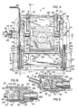
- a vehicle seat suspension embodying the present invention and generally identified by the reference numeral 10 is shown incorporated into the base or bottom portion of a vehicle seat 12 which is anchored to the floor 14 of the vehicle.
- the vehicle seat 12 includes a seat cushion 16 and a seat back 18 which may either be fixed or pivotably adjustable with respect to the seat cushion 16.
- a first adjusting mechanism 20 is provided to longitudinally adjust the position of the vehicle seat 12 relative to the floor 14 of the vehicle, while a second adjusting mechanism 22 is provided to alter the resilient suspension of the vehicle seat 12 according to the weight of the seat occupant.
- the arrangement of the first and second adjusting mechanisms 20, 22 results in the seat having a relatively low profile desirable to the purchasers of such suspensions.
- the vehicle seat suspension 10 includes a top frame 24, a bottom frame 26, and a substantially fully collapsible scissors linkage 28 interposed between the top and bottom frames 24, 26.
- the first adjusting mechanism 20 is conveniently isolated in the top frame 24 and comprises a pair of adjustment channel assemblies 30.
- the second adjusting mechanism 22 is located between the top and bottom frames 24, 26 and comprises a suspension spring 32, a cam assembly 33 defined by a cam follower 34 and a cam 36, an adjustment plate 38, an adjustment lever 40, a cylindrical spindle 42, a pivot pin 44 and a weight adjustment knob 46.
- Top frame 24 is a generally rectangular, solid plate 48 preferably fabricated from steel.
- Plate 48 has an upper surface to which a tubular seat framework 49 (Fig. 4) carrying the vehicle seat 12 is secured such as by welding.
- a tubular seat framework 49 Fig. 4
- a pair of spaced, inwardly facing top front channels 50 Depending from a bottom surface of plate 48 at a forward end thereof is a pair of spaced, inwardly facing top front channels 50.
- Each of the channels 50 is closed by end walls 51, 52 which define front and rear limits of travel for components of scissors linkage 28 to be described hereafter.
- the pair of spaced adjustment channel assemblies 30 which are operatively tied together by a connecting wire 53.
- each adjustment channel assembly 30 comprises an elongated adjusting channel 54 which is U-shaped in cross-section and has an upper wall 56 and a bottom wall 58 connected by a sidewall 60. Bottom wall 58 and a bottom portion of sidewall 60 are formed along their lengths with a series of slots 62.
- a front ear 64 is secured generally perpendicularly to a forward end of sidewall 60 while a rear ear 66 is similarly joined perpendicularly to a rear end of sidewall 60. Both front ear 64 and rear ear 66 are formed with a circular opening 68 therethrough so that each opening 68 is aligned with the other.
- a comb 70 which is also U-shaped in cross-section has a bottom wall 72 which is formed with a multiplicity of teeth 74, and interconnects an upwardly extending front tab 76 at a forward end of comb 70 with an upwardly extending rear tab 78 at a rear end of comb 70. Both front tab 76 and rear tab 78 are provided with a circular aperture 80 therethrough so that each aperture 80 is aligned with the other. Referring to Figs.
- adjusting channel 54 is juxtaposed relative to comb 70 such that the teeth 74 of comb 70 are receivable in slots 62 of adjusting channel 54, and the openings 68 in front and rear ears 64, 66 are aligned with apertures 80 in front and rear tabs 76, 78.
- an elongated release rod 82 extends through the aligned openings 68 and apertures 80.
- the release rod 82 on the left side of the vehicle seat 12 includes an extension 84 which runs beyond the front end of the seat and terminates in a curved or bent handle 86 accessible to the seat occupant outside the left front corner of the seat.
- each release rod 82 includes a U-shaped turning channel 88 fixed thereto which abuts front tab 76 on comb 70.
- the rear end of each release rod 82 projects beyond rear tab 66, passes through a retaining ring 90 and is received in a wire eye 92 where it is secured by means of a spring pin 94 inserted in aligned transverse holes 96, 98 in wire eye 92 and release rod 82, respectively.
- a torsion latch spring 100 surrounds a portion of each release rod 82 and is interposed between front ear 64 of adjusting channel 54 and front tab 76 of comb 70 (Fig. 4).
- Each torsion latch spring 100 has one end 102 biased against bottom wall 72 of comb 70 and another end 104 biased against top plate 48. With this arrangement, each spring 100 functions to normally retain the teeth 74 of each comb 70 in the slots 62 of its respective adjusting channel 54.
- bottom frame 26 is a generally rectangular, solid plate 106 preferably constituted of steel which is adapted to be fastened by bolts 107 passing through holes 108 formed in the periphery thereof. Alternatively, studs extending upwardly from the floor of the vehicle pass through holes 108 and can be secured by nuts (not shown). Plate 106 has an upper surface upon a forward end of which a pair of spaced, inwardly facing, bottom front channels 110 are secured, and upon a rear end of which a pair of spaced, inwardly facing bottom rear channels 112 are mounted.
- Bottom frame 26 includes a neck portion 113 to which an upstanding, three-sided adjustment bracket 114 is attached.
- Top frame 24 and bottom frame 26 are connected one above the other in parallel by scissors linkage 28 formed by a pair of outer links 116 and a pair of inner links 118.
- the mid portion of each outer link 116 is pivotally connected to a mid portion of each inner link 118 by a pivot pin 120 which is shielded by an outer sleeve 122 best depicted in Figs. 10 and 11.
- the inner end of each pivot pin 120 is mounted for rotation to a side of a generally rectangular support platform 124 having a central opening 126 formed therein.
- the front ends of inner links 118 are interconnected by a transverse shaft 128, each end of which carries a first slide block 130 slidably receivable in a respective one of the top front channels 50 on top frame 24.
- inner links 118 are joined together by a cross shaft 132, each end of which carries a stationary block 134 receivable and fixed by fastener 135 in a respective one of the bottom rear channels 112 on bottom frame 26.
- the front ends of outer links 116 each carry a second slide block 136 slidably receivable and connected by fastener 137 in a respective one of the bottom front channels 110 on bottom frame 26.
- the rear ends of outer links 116 are connected by a cross member 138, each end of which carries an adjusting block 140 slidably receivable in a respective one of the adjustment channel assemblies 30 on top frame 24.
- Each of adjusting blocks 140 has a bottom surface formed with grooves 142 which are capable of mating with teeth 74 on each comb 70.
- inner and outer links 116, 118 are spaced from each other such that first slide blocks 130 lie substantially inwardly of and almost at the same level as secondary slide blocks 136 (Fig. 13) when scissors linkage 28 is generally fully collapsed.
- stationary blocks 134 also lie inwardly of and at nearly the same level as adjusting blocks 140, and that spring 32 is further compressed so that its coils will be tightly bunched upon one another.
- inner links 118, cross/shaft 132, and blocks 134 lie inwardly of outer links 116, cross member 138 and blocks 140, blocks 134 being spaced forwardly of blocks 140.
- cylindrical spindle 42 extends vertically upwardly from bottom frame 26 and passes through a circular opening 144 formed by a continuous wall 146 on a distal end of adjustment plate 38 overlying bottom plate 106.
- the diameter of opening 144 is larger than the diameter of spindle 42 so that spindle 42 lies in spaced relationship with wall 146.
- the proximal end of adjustment plate 38 is disposed in adjustment bracket 114 and is joined to the bottom of adjustment lever 40 which in turn is pivotally mounted on pivot pin 44 and adjustment bracket 38.
- Adjustment knob 46 has a shaft 148 screw threaded into adjustment bracket 38 and is manipulable against adjustment lever 40 to selectively slide the adjustment plate 38 back and forth on bottom plate 106 over a limited distance defined by the clearance between spindle 42 and opening 144.
- cam 36 Disposed over spindle 42 and fixed to adjustment plate 38 is cam 36 which includes a series of inclined wedges or ramps 147 engageable with complementary ramped surfaces 149 on overlying cam follower 34.
- Extending outwardly from the base of cam follower 34 is a lip 150 which serves to seat a small or lower end of spring 32 which encircles cam follower 34 and terminates in a large or upper end of spring 32 being seated against support platform 124.
- Spring 32 is installed with a predetermined preload force which urges the top frame 24 away from bottom frame 26 and prevents top frame 24 from collapsing on bottom frame 26.
- spring 32 is preferably a single, conical compression spring having a metallic constitution.
- the invention also contemplates the use of multiple, cooperating plastic springs 32' such as constructed from Delrin, as illustrated in Fig. 12.
- each adjusting block 130 abuts forward end wall 51 of each channel 50, and each slide block 140 is accordingly positioned at the forward end of each adjusting channel 54.
- suspension spring 32 Due to the upward movement of cam follower 34, suspension spring 32 is further compressed thereby increasing the preload force which results in a stiffer ride.
- suspension spring 32 When suspension spring 32 is fully compressed, the coils of the spring 32 are tightly bunched together, as shown in Fig. 13, and scissors linkage 28 is substantially fully collapsed, thereby creating an extremely favorable low profile.
- the vertical suspension stroke afforded by the elements used is approximately 1.75 inches which creates a suitable margin of comfort for most seat occupants.
- the suspension may be otherwise tailored such as by employing different size cam members or using different and/or multiple springs such as the plastic springs 32' shown in Fig. 12.
- the present invention provides a seat suspension having both fore and aft adjustment and weight compensation adjustment constructed and arranged in a manner which will produce a low profile seat meeting the dimensional tolerances of seat purchasers.
- the present invention comprises a minimal of parts which improve its operability and maintenance and reduce its weight and cost.
Landscapes
- Engineering & Computer Science (AREA)
- Aviation & Aerospace Engineering (AREA)
- Transportation (AREA)
- Mechanical Engineering (AREA)
- Seats For Vehicles (AREA)
Claims (24)
- Fahrzeugsitzfederung (10) mit niedrigem Profil, die folgendes aufweist:einen unteren Rahmen (26), der zur Anbringung an dem Fahrzeug ausgebildet ist;einen oberen Rahmen (24), der über dem unteren Rahmen (26) positioniert und zur Abstützung eines Sitzes (12) darauf ausgebildet ist;ein Paar von beabstandeten oberen vorderen Kanälen (50), die an dem oberen Rahmen (24) festgelegt sind;ein im wesentlichen vollständig zusammenklappbares Scherengestänge (28), das zwischen dem unteren Rahmen (26) und dem oberen Rahmen (24) in Verbindung mit diesen angeordnet ist und es dem unteren Rahmen (26) und dem oberen Rahmen (24) ermöglicht, sich relativ zueinander im wesentlichen parallel zu bewegen;eine zwischen dem oberen Rahmen (24) und dem unteren Rahmen (26) angeordnete Vorspannungsanordnung (32), die eine Vorspannkraft hat, die den oberen Rahmen (24) von dem unteren Rahmen (26) wegdrückt;eine erste Einstelleinrichtung (20), die in dem oberen Rahmen (24) positioniert ist und selektiv eine Vorwärts- und Rückwärtseinstellung des oberen Rahmens (24) relativ zu dem unteren Rahmen (26) zuläßt; undeine zweite Einstelleinrichtung (22), die zwischen dem unteren Rahmen (26) und dem oberen Rahmen (24) positioniert ist und selektiv eine Einstellung an der Vorspannungsanordnung (32) in Abhängigkeit von dem Gewicht einer auf dem Sitz (12) befindlichen Person ermöglicht durch Umsetzen einer horizontalen Kraft, die auf eine Einstellplatte (38) entlang dem unteren Rahmen (26) aufgebracht wird, in eine vertikale Kraft, welche die Vorspannkraft der Vorspannungsanordnung (32) beeinflußt, wobei die Einstellplatte (38) ein daran befestigtes Nockenelement (36) hat, wobei die Horizontalkraft die Einstellplatte (38) entlang dem unteren Rahmen (26) gleitverschiebt und dadurch ein Federelement der Vorspannungsanordnung (32) in einer Vertikalrichtung verlagert,wobei die erste Einstelleinrichtung (20) ein Paar von beabstandeten Einstellkanalanordnungen (30) aufweist, die rückwärts und seitlich von den oberen vorderen Kanälen (56) an dem oberen Rahmen (24) befestigt sind, und
dadurch gekennzeichnet, daß
jede von den Einstellkanalanordnungen (30) aufweist: einen Einstellkanal (54), der eine obere Wand (56), eine untere Wand (58) und eine die obere Wand (56) und die untere Wand (58) verbindende Seitenwand (60) hat, wobei die untere Wand (58) mit folgendem ausgebildet ist: einer Vielzahl von sie durchsetzenden Schlitzen (62), einer vorderen Öse (64), die allgemein senkrecht zu der Seitenwand (60) an einem Vorderende der Seitenwand (60) befestigt ist, und eine hintere Öse (66), die allgemein senkrecht zu der Seitenwand (60) an einem Hinterende der Seitenwand (60) befestigt ist, wobei die vordere Öse (64) und die hintere Öse (66) jeweils mit einem Durchgangsloch (68) ausgebildet sind. - Fahrzeugsitzfederung mit niedrigem Profil nach Anspruch 1, die ein Paar von beabstandeten unteren vorderen Kanälen (11), die an dem unteren Rahmen (26) befestigt sind, und ein Paar von beabstandeten unteren hinteren Kanälen (112) aufweist, die an dem unteren Rahmen (26) befestigt sind.
- Fahrzeugsitzfederung mit niedrigem Profil nach Anspruch 1, wobei jede der Einstellkanalanordnungen (30) ferner folgendes aufweist: einen Kamm (70), der folgendes hat: eine untere Wand (72), die mit einer Vielzahl von Zähnen (74) versehen ist, eine vordere Nase (76), die nach oben und allgemein senkrecht zu der unteren Wand (72) des Kamms (70) an einem Vorderende des Kamms (70) verläuft, und eine hintere Nase (78), die nach oben und allgemein senkrecht zu der unteren Wand (72) des Kamms (70) an einem Hinterende des Kamms (70) verläuft, wobei die vordere Nase (76) und die hintere Nase (78) jeweils mit einem Durchgangsloch (80) ausgebildet sind.
- Fahrzeugsitzfederung mit niedrigem Profil nach Anspruch 1, wobei der Einstellkanal (54) relativ zu dem Kamm (70) so daran angrenzt, daß die Zähne (76) des Kamms (70) in den Schlitzen (62) des Einstellkanals (54) aufnehmbar sind und die Löcher (68) in der vorderen Öse (64) und der hinteren Öse (66) mit den Löchern (80) in der vorderen Nase (76) und der hinteren Nase (78) ausgefluchtet sind.
- Fahrzeugsitzfederung mit niedrigem Profil nach Anspruch 4, die eine drehbare Lösestange (82) aufweist, die sich durch die ausgefluchteten Löcher (68) und die Löcher (80) erstreckt, wobei die Lösestange (82) folgendes hat: ein Vorderende, das einen Drehkanal (88) trägt, der an der vorderen Nase (76) in Eingriff ist, und ein Hinterende, das in einer Drahtöse (92) aufgenommen ist und einen Querhohlraum aufweist, wobei die Drahtöse (92) in Anlage an der hinteren Öse (66) angebracht ist und die Drahtöse (92) einen Federbolzen (94) trägt, der in dem Querhohlraum (98) in Eingriff ist, so daß ein Drehen der Lösestange (82) die Zähne (74) des Kamms (70) in und außer Eingriff mit den Schlitzen (62) in dem Einstellkanal (54) bewegt.
- Fahrzeugsitzfederung mit niedrigem Profil nach Anspruch 5, die eine Schraubenfeder (100) aufweist, die einen Bereich der Lösestange (82) umgibt und zwischen der vorderen Öse (64) des Einstellkanals (54) und der vorderen Nase (76) des Kamms (70) angeordnet ist, wobei das eine Ende der Schraubenfeder (100) gegen die untere Wand (72) des Kamms (70) vorgespannt ist und das andere Ende gegen die vordere Öse (64) des Einstellkanals vorgespannt ist, wobei die Feder (100) die Funktion hat, die Zähne (74) des Kamms (70) normalerweise in den Schlitzen des Einstellkanals (54) festzuhalten.
- Fahrzeugsitzfederung mit niedrigem Profil nach Anspruch 5, die einen Verbindungsdraht (53) aufweist, der die jeweiligen Drahtösen (92) an den Einstellkanalanordnungen miteinander verbindet.
- Fahrzeugsitzfederung (10) mit niedrigem Profil nach Anspruch 1, wobei die zweite Einstelleinrichtung (22) aufweist: einen Schaft (42), der sich von dem unteren Rahmen (26) nach oben erstreckt, eine Nockeneinheit (33), die den Schaft umschließt, wobei die Einstellplatte (38) ein proximales Ende, das gleitbar auf dem unteren Rahmen (26) angeordnet ist und den Schaft (42) umgibt, und ein distales Ende hat, das mit einem Einstellhebel (40) versehen ist, der relativ zu dem unteren Rahmen (26) schwenkbar angebracht ist, und eine Stellschraube (46), die in den unteren Rahmen (26) eingedreht und mit dem Einstellhebel (40) in Eingriff ist; und
wobei die Nockeneinheit (33) einen Nockenfolger (34) aufweist, der an dem Nocken (36) bewegbar angebracht ist und eine Lippe (150) hat, die davon nach außen verläuft. - Fahrzeugsitzfederung mit niedrigem Profil nach Anspruch 8, wobei das Scherengestänge (28) eine Tragplattform (124) aufweist, die unter dem oberen Rahmen (24) angeordnet ist.
- Fahrzeugsitzfederung mit niedrigem Profil nach Anspruch 9, wobei die Vorspannungsanordnung (32) wenigstens eine Feder aufweist, die ein erstes Ende hat, das an der Tragplattform (124) anliegt, und ein zweites Ende hat, das an der Lippe (150) des Nockenfolgers (34) des Nockens (36) anliegt.
- Fahrzeugsitzfederung mit niedrigem Profil nach Anspruch 9, wobei das Scherengestänge (28) ferner ein Paar von äußeren Gelenkelementen (116) und ein Paar von inneren Gelenkelementen (118) aufweist, wobei ein Mittelbereich von jedem der äußeren Gelenkelemente (116) mit einem Mittelbereich von jedem der inneren Gelenkelemente (118) und mit einem Bereich der Tragplattform (124) schwenkbar verbunden ist.
- Fahrzeugsitzfederung mit niedrigem Profil nach Anspruch 11, wobei jedes von den äußeren Gelenkelementen (116) und jedes von den inneren Gelenkelementen (118) ein Vorderende und ein Hinterende hat.
- Fahrzeugsitzfederung mit niedrigem Profil nach Anspruch 12, wobei das Vorderende von jedem von den äußeren Gelenkelementen (116) allgemein außerhalb von und benachbart zu einem jeweiligen Vorderende der inneren Gelenkelemente (118) liegt.
- Fahrzeugsitzfederung mit niedrigem Profil nach Anspruch 12, wobei die Vorderenden der jeweiligen inneren Gelenkelemente (118) durch eine Querachse (128) miteinander verbunden sind, wobei jedes Ende derselben ein erstes Gleitstück (130) trägt, das in einem jeweiligen der oberen vorderen Kanäle (50) an dem oberen Rahmen (24) gleitbar aufgenommen ist.
- Fahrzeugsitzfederung mit niedrigem Profil nach Anspruch 12, wobei die Hinterenden der jeweiligen inneren Gelenkelemente (118) durch eine Querachse (132) miteinander verbunden sind, wobei jedes Ende derselben einen ortsfesten Block (134) trägt, der in einem jeweiligen der unteren hinteren Kanäle (112) an dem unteren Rahmen (26) aufgenommen ist.
- Fahrzeugsitzfederung mit niedrigem Profil nach Anspruch 12, wobei das Vorderende von jedem der äußeren Gelenkelemente (116) ein zweites Gleitstück (136) trägt, das in einem jeweiligen der unteren vorderen Kanäle (110) an dem unteren Rahmen (26) gleitbar aufgenommen ist.
- Fahrzeugsitzfederung (10) mit niedrigem Profil nach Anspruch 1,
wobei das Scherengestänge (28) zwei Paare von Gelenkelementen (116; 118) aufweist, wobei die Gelenkelemente jedes Paars jeweils an einem Mittelbereich schwenkbar miteinander verbunden und so orientiert sind, daß eines der Paare von Gelenkelementen (116; 118) obere Vorderenden aufweist, wobei diese oberen Vorderenden jeweils ein Gleitstück (130) tragen, das in einem jeweiligen der oberen vorderen Kanäle (50) aufgenommen ist, und wobei das andere der Paare von Gelenkelementen (116; 118) jeweils ein oberes Hinterende hat, das einen Einstellblock (140) trägt, der in einer jeweiligen der Einstellkanalanordnungen (36) gleitbar aufgenommen ist; und
die vordere Nase (76) und die hintere Nase (78) jeweils mit einem Durchgangsloch (80) ausgebildet sind, wobei jede der Einstellkanalanordnungen (30) einen darin gleitbar aufgenommenen Einstellblock (140) hat,
wobei jeder der Einstellblöcke (140) eine untere Oberfläche hat, die mit Nuten (142) ausgebildet ist, die mit den Zähnen (74) des Kamms (70) zusammenpassen. - Fahrzeugsitzfederung mit niedrigem Profil nach Anspruch 1, die ferner folgendes aufweist:eine Achse (42), die an dem unteren Rahmen (26) angebracht ist und davon nach oben verläuft;eine Einstellplatte (38), die an dem unteren Rahmen (26) gleitbar angeordnet ist, wobei die Einstellplatte (38) eine fortlaufende Wand (146) hat, die eine Öffnung bildet, durch welche die Achse (42) in beabstandeter Beziehung zu der Wand vorspringt;einen Nocken (36), der an der Einstellplatte (38) befestigt ist und die Achse in beabstandeter Beziehung dazu umschließt;einen Nockenfolger (34), der auf dem Nocken (36) bewegbar angebracht ist und die Achse (42) umschließt, wobei der Nockenfolger (34) eine davon nach außen verlaufende Lippe (150) hat; undeine Feder (32), deren eines Ende an der Federhalterung anliegt und deren anderes Ende an der Lippe (150) anliegt, wobei auf die Feder (32) eine Vorspannkraft aufgebracht wird, die den oberen Rahmen (24) von dem unteren Rahmen (26) wegdrückt;wobei ein Gleiten der Einstellplatte (38) und des Nockens (36) zu der Achse (42) hin den Nockenfolger (34) veranlaßt, sich aufwärts zu bewegen, um die Feder (32) weiter zusammenzudrücken und die auf sie wirkende Vorspannkraft zu erhöhen.
- Fahrzeugsitzfederung mit niedrigem Profil nach Anspruch 18, wobei die einstellbare Platte (38) einen Einstellhebel (40) aufweist, der an dem unteren Rahmen (26) schwenkbar angebracht ist und mit einer in die untere Platte (26) geschraubten Stellschraube (46) in Eingriff bringbar ist.
- Fahrzeugsitzfederung mit niedrigem Profil nach Anspruch 18, wobei der Nocken (36) eine Serie von schrägen Rampen (147) aufweist.
- Fahrzeugsitzfederung mit niedrigem Profil nach Anspruch 18, wobei der Nockenfolger (34) eine Serie von schrägen Rampenflächen (149) aufweist, die mit den Rampen (147) in Eingriff sind.
- Fahrzeugsitzfederung mit niedrigem Profil nach Anspruch 18, wobei der Nockenfolger (34) entlang der Achse (42) bewegbar aufwärts und abwärts führbar ist.
- Fahrzeugsitzfederung mit niedrigem Profil nach Anspruch 28, wobei die Feder (32) eine konische Druckfeder (32) aufweist.
- Fahrzeugsitzfederung mit niedrigem Profil nach Anspruch 18, wobei die Feder (32) ein Paar von zusammenwirkenden Kunststoff-Federn (32) aufweist.
Applications Claiming Priority (3)
| Application Number | Priority Date | Filing Date | Title |
|---|---|---|---|
| US08/691,259 US5765802A (en) | 1996-08-02 | 1996-08-02 | Low profile seat suspension |
| US691259 | 1996-08-02 | ||
| PCT/US1997/013012 WO1998005526A2 (en) | 1996-08-02 | 1997-07-24 | Low profile vehicle seat suspension construction and combined sliding mechanism |
Publications (2)
| Publication Number | Publication Date |
|---|---|
| EP0915775A2 EP0915775A2 (de) | 1999-05-19 |
| EP0915775B1 true EP0915775B1 (de) | 2006-06-07 |
Family
ID=24775799
Family Applications (1)
| Application Number | Title | Priority Date | Filing Date |
|---|---|---|---|
| EP97936200A Expired - Lifetime EP0915775B1 (de) | 1996-08-02 | 1997-07-24 | Fahrzeugsitzaufhängung mit niedriger profilkonstruktion und kombiniertem längenverstellmechanismus |
Country Status (5)
| Country | Link |
|---|---|
| US (2) | US5765802A (de) |
| EP (1) | EP0915775B1 (de) |
| CA (1) | CA2264640A1 (de) |
| DE (1) | DE69736064T2 (de) |
| WO (1) | WO1998005526A2 (de) |
Families Citing this family (47)
| Publication number | Priority date | Publication date | Assignee | Title |
|---|---|---|---|---|
| US20070135982A1 (en) | 1995-06-07 | 2007-06-14 | Automotive Technologies International, Inc. | Methods for Sensing Weight of an Occupying Item in a Vehicular Seat |
| US7860626B2 (en) * | 1995-06-07 | 2010-12-28 | Automotive Technologies International, Inc. | Vehicular heads-up display system with adjustable viewing |
| DE19647448C2 (de) * | 1996-11-16 | 1999-06-02 | Keiper Gmbh & Co | Längsverstellvorrichtung für Sitze, insbesondere Kraftfahrzeugsitze |
| US6056354A (en) * | 1998-06-12 | 2000-05-02 | Shin Yen Enterprise Co., Ltd. | Foldable chair frame |
| US6264180B1 (en) * | 1999-05-27 | 2001-07-24 | Sears Manufacturing Co. | Axially adjustable roller assembly |
| JP2001138778A (ja) * | 1999-11-16 | 2001-05-22 | Aisin Seiki Co Ltd | シートスライド装置 |
| AU777671B2 (en) * | 2000-01-04 | 2004-10-28 | Kab Seating Pty Ltd | Suspension seat |
| AU728411B3 (en) | 2000-01-04 | 2001-01-11 | G & J Lewis Enterprises Pty Ltd | Suspension seat |
| NZ521065A (en) * | 2000-03-10 | 2005-02-25 | British American Tobacco Co | Process for treating tobacco to reduce the content of nitrosamines |
| US6336619B1 (en) * | 2000-06-21 | 2002-01-08 | Michigan Seat Company | Adjustable seat platform |
| DE10040535C1 (de) * | 2000-08-18 | 2001-10-18 | Grammer Ag | Gefederter Fahrzeugsitz |
| US20020190185A1 (en) * | 2001-06-19 | 2002-12-19 | Dale Ropp | Seat suspension shock absorber |
| US20040043363A1 (en) * | 2002-09-03 | 2004-03-04 | Elmar Dorner | Tutor interface with content based messaging |
| US6719258B2 (en) | 2002-09-16 | 2004-04-13 | Activar, Inc. | Shock and vibration isolation apparatus for motor vehicles seats |
| US7556233B2 (en) * | 2003-04-24 | 2009-07-07 | Sears Manufacturing Co. | Dual track seat adjustment apparatus |
| DE602004024523D1 (de) | 2003-06-11 | 2010-01-21 | H O Bostrom Co Inc | Sitzaufhängung mit niedrigem profil |
| US7172250B2 (en) * | 2004-09-27 | 2007-02-06 | Yao-Chuan Wu | Adjustable chassis for chair |
| FR2894639B1 (fr) * | 2005-12-14 | 2011-08-19 | Renault Sas | Appui de ressort a flexibilite variable |
| US7568675B2 (en) * | 2006-06-23 | 2009-08-04 | Caterpillar Inc. | Scissor suspension |
| US7506932B2 (en) * | 2007-05-31 | 2009-03-24 | H.O. Bostrom Company, Inc. | Adjustable jockey seat assembly |
| DE112008003412T5 (de) | 2007-12-21 | 2010-11-18 | Lear Corporation, Southfield | Fahrzeugsitz |
| DE102008023120B4 (de) * | 2008-05-07 | 2010-06-10 | Keiper Gmbh & Co. Kg | Fahrzeugsitz, insbesondere Nutzfahrzeugsitz |
| US8197004B2 (en) | 2008-12-01 | 2012-06-12 | Milsco Manfacturing Company, A Unit Of Jason Incorporated | Adjustable vehicle seat suspension |
| US8585004B1 (en) | 2009-01-26 | 2013-11-19 | Atwood Mobile Products Llc | Air ride seat pedestal with independent height adjustment |
| DE102009031415B4 (de) * | 2009-07-02 | 2011-04-14 | Keiper Gmbh & Co. Kg | Fahrzeugsitz, insbesondere Nutzfahrzeugsitz |
| DE102010010290B4 (de) * | 2010-03-04 | 2017-10-26 | Grammer Aktiengesellschaft | Fahrzeugsitz mit Gleitelement |
| DE102010033419A1 (de) | 2010-08-04 | 2012-02-09 | Grammer Aktiengesellschaft | Horizontfedereinrichtung für Fahrzeugsitze mit Elastomerfederelement mit progressiver Federkennlinie |
| DE102010035888B4 (de) | 2010-08-30 | 2018-05-09 | Grammer Ag | Fahrzeugsschwingungsvorrichtung |
| DE102010045114B4 (de) | 2010-09-13 | 2019-12-19 | Grammer Aktiengesellschaft | Verfahren zum Betreiben einer Fahrzeugdämpfungseinrichtung für einen Fahrzeugsitz / eine Fahrzeugkabine und Fahrzeugdämpfungseinrichtung für einen Fahrzeugsitz / eine Fahrzeugkabine |
| DE102010054752B4 (de) | 2010-09-13 | 2012-06-28 | Grammer Aktiengesellschaft | Gefederte Mehrpunktlagerung für Fahrzeuge mit Elastomerfederelement |
| DE102010048210B4 (de) | 2010-10-13 | 2021-09-16 | Grammer Aktiengesellschaft | Fahrzeugsitz mit Fluidfeder |
| DE102010051325B4 (de) | 2010-11-16 | 2020-11-26 | Grammer Aktiengesellschaft | Sitzfuß für einen Personensitz |
| DE102010052619A1 (de) * | 2010-11-29 | 2012-05-31 | Grammer Aktiengesellschaft | Fahrzeugsitz mit geführten Scherenarmen |
| DE102010053752A1 (de) | 2010-12-08 | 2012-06-14 | Grammer Aktiengesellschaft | Fahrzeugschwingungsvorrichtung für Fahrzeugsitze oder Fahrzeugkabinen |
| DE102010055342B4 (de) | 2010-12-21 | 2015-03-26 | Grammer Aktiengesellschaft | Horizontale Sitzfedereinrichtung |
| DE102010055344A1 (de) | 2010-12-21 | 2012-06-21 | Grammer Aktiengesellschaft | Horizontale Sitzverstellung mit Stellglied |
| DE102011009530B4 (de) | 2011-01-26 | 2014-04-10 | Grammer Aktiengesellschaft | Fahrzeugschwingungsvorrichtung, Fahrzeugsitz oder Fahrgastzelle bzw. Fahrzeugkabine eines Fahrzeuges |
| DE102011015364B4 (de) | 2011-03-28 | 2012-10-11 | Grammer Aktiengesellschaft | Fahrzeugsitz mit einer Tragstruktur |
| DE102011053647B4 (de) | 2011-09-15 | 2022-02-03 | Grammer Aktiengesellschaft | Fahrzeugsitz mit einer Federungsvorrichtung und Kraftfahrzeug |
| JP5865164B2 (ja) * | 2012-04-16 | 2016-02-17 | オイレス工業株式会社 | 離間距離調整装置およびこれを用いた搬送装置 |
| US9211814B2 (en) * | 2012-12-13 | 2015-12-15 | Polaris Industries Inc. | Seat adjusting mechansim for vehicle |
| ITMO20130002A1 (it) * | 2013-01-10 | 2014-07-11 | Seat S R L | Sedile ammortizzato a regolazione migliorata. |
| EP3253614A4 (de) | 2015-06-04 | 2018-09-19 | Milsco Manufacturing Company | Modulares vorwärts- und rückwärtssitzpositionseinstellsystem mit integriertem schwingungsdämpfungssystem |
| DE102015113176B4 (de) | 2015-08-10 | 2021-12-30 | Grammer Aktiengesellschaft | Horizontalschwingungsvorrichtung für einen Fahrzeugsitz |
| WO2017176902A1 (en) * | 2016-04-05 | 2017-10-12 | Pride Mobility Products Corporation | Seat positioning system for a wheelchair |
| DE102016108159B4 (de) * | 2016-05-03 | 2020-06-18 | Grammer Aktiengesellschaft | Fahrzeugsitz mit Rollenführung |
| US12365275B2 (en) * | 2021-09-03 | 2025-07-22 | Roswell Canada Inc. | Suspension component |
Family Cites Families (34)
| Publication number | Priority date | Publication date | Assignee | Title |
|---|---|---|---|---|
| US2460596A (en) * | 1949-02-01 | Cushion support | ||
| US2365468A (en) * | 1940-05-04 | 1944-12-19 | Bassick Co | Tilting chair mounting |
| DE6811419U (de) * | 1968-12-14 | 1969-08-28 | Dieter Dipl Ing Fock | Fahrzeugsitz mit federnd abgestuetzten scherenhebeln |
| DE6905646U (de) * | 1969-02-13 | 1969-05-14 | Isringhausen Geb | Fahrzeugsitz mit abgefederten scherenhebeln |
| DE6924745U (de) * | 1969-06-20 | 1969-11-13 | Isringhausen Fa Geb | Fahrzeugsitz mit abgefederten scherenhebeln und schwingungsdaempfung |
| US3572219A (en) * | 1969-10-15 | 1971-03-23 | Robertshaw Controls Co | Multiple-cam regulator converter |
| US3633864A (en) * | 1970-01-19 | 1972-01-11 | Herscheal W Miller | Adjustable seat support |
| DE2233674C3 (de) * | 1972-07-08 | 1981-01-08 | Bremshey Ag, 5650 Solingen | Abgefederter Sitz, insbesondere Fahrzeugsitz |
| FR2208353A5 (de) * | 1972-11-28 | 1974-06-21 | Sable Freres Int | |
| US4125242A (en) * | 1974-09-28 | 1978-11-14 | Messrs. Willibald Grammer | Spring mounted seat with height adjustment |
| FR2357397A1 (fr) * | 1976-07-09 | 1978-02-03 | Sifra | Siege suspendu pour tous vehicules |
| DE2707184A1 (de) * | 1977-02-18 | 1978-08-24 | Bremshey Ag | Fahrzeugsitz |
| SU804945A1 (ru) * | 1977-11-04 | 1981-02-15 | Vasilev Vyacheslav M | Устройство дл заневоливани пружин |
| FR2447829A1 (fr) * | 1979-02-02 | 1980-08-29 | Sable Freres Int | Dispositif de suspension elastique de siege de vehicule |
| FR2460225A1 (fr) * | 1979-06-28 | 1981-01-23 | Sable Freres Int | Dispositif de suspension elastique de siege de vehicule avec reglage longitudinal |
| FR2470024A1 (fr) * | 1979-11-27 | 1981-05-29 | Sable Freres Int | Support de siege de vehicule avec dispositif incorpore d'amortissement des accelerations longitudinales |
| US4384701A (en) * | 1980-10-01 | 1983-05-24 | Uop Inc. | Fore and aft adjustment and isolation assembly |
| JPS59151586U (ja) * | 1983-03-29 | 1984-10-11 | 三菱電機株式会社 | ミシン駆動装置のレバ−機構 |
| DE3501853A1 (de) * | 1985-01-22 | 1986-07-24 | Lisega Kraftwerkstechnik GmbH, 2730 Zeven | Aufhaengevorrichtung fuer sich verschiebende lasten, insbesondere rohrleitungen u.dgl. |
| JPS61128140U (de) * | 1985-01-31 | 1986-08-11 | ||
| JPH0615312B2 (ja) * | 1986-04-07 | 1994-03-02 | 株式会社大井製作所 | 自動車用シートスライド装置 |
| AU588332B2 (en) * | 1986-07-04 | 1989-09-14 | Tachi-S Co., Ltd. | Seat suspension device |
| JPS6349560A (ja) * | 1986-08-20 | 1988-03-02 | Oi Seisakusho Co Ltd | シ−トスライド装置におけるロツク部材の復帰用ばね |
| US4771975A (en) * | 1986-09-11 | 1988-09-20 | Semec, Inc. | Vehicle seat position adjuster |
| US4822094A (en) * | 1988-01-12 | 1989-04-18 | J. I. Case Company | Tractor seat suspension mechanism with automatic seat stop |
| US4856763A (en) * | 1988-05-19 | 1989-08-15 | Sears Manufacturing Company | Mechanical seat suspension with concentric cam surfaces |
| US4926760A (en) * | 1989-01-27 | 1990-05-22 | Sack Allen J | Self leveling tables |
| JP3043819B2 (ja) * | 1991-01-21 | 2000-05-22 | アイシン精機株式会社 | 車両用シートスライド装置 |
| US5048787A (en) * | 1990-04-10 | 1991-09-17 | Tachi-S Co., Ltd. | Slide rail for automotive seat |
| US5222709A (en) * | 1990-04-13 | 1993-06-29 | Rosdon Engineering And Manufacturing Pty. Ltd. | Vehicle seat suspension unit |
| JPH0439134U (de) * | 1990-07-31 | 1992-04-02 | ||
| US5251864A (en) * | 1992-04-21 | 1993-10-12 | Tachi-S Co., Ltd. | Suspension device for vehicle seat |
| US5358207A (en) * | 1992-12-01 | 1994-10-25 | Bertrand Faure Ltd. | Automotive seat track locking mechanism |
| JP2618179B2 (ja) * | 1993-04-27 | 1997-06-11 | 池田物産株式会社 | パワーシートスライド装置 |
-
1996
- 1996-08-02 US US08/691,259 patent/US5765802A/en not_active Expired - Lifetime
-
1997
- 1997-07-24 DE DE69736064T patent/DE69736064T2/de not_active Expired - Lifetime
- 1997-07-24 CA CA002264640A patent/CA2264640A1/en not_active Abandoned
- 1997-07-24 EP EP97936200A patent/EP0915775B1/de not_active Expired - Lifetime
- 1997-07-24 WO PCT/US1997/013012 patent/WO1998005526A2/en not_active Ceased
- 1997-10-14 US US08/950,346 patent/US5871198A/en not_active Expired - Fee Related
Also Published As
| Publication number | Publication date |
|---|---|
| WO1998005526A3 (en) | 1998-05-28 |
| WO1998005526A2 (en) | 1998-02-12 |
| EP0915775A2 (de) | 1999-05-19 |
| CA2264640A1 (en) | 1998-02-12 |
| DE69736064D1 (de) | 2006-07-20 |
| US5871198A (en) | 1999-02-16 |
| DE69736064T2 (de) | 2007-03-15 |
| US5765802A (en) | 1998-06-16 |
Similar Documents
| Publication | Publication Date | Title |
|---|---|---|
| EP0915775B1 (de) | Fahrzeugsitzaufhängung mit niedriger profilkonstruktion und kombiniertem längenverstellmechanismus | |
| EP1631474B1 (de) | Sitzaufhängung mit niedrigem profil | |
| US5251864A (en) | Suspension device for vehicle seat | |
| US4334709A (en) | Seat for vehicle | |
| US6267344B1 (en) | Vehicle seat with suspension mechanism | |
| US6655733B2 (en) | Variable movement headrest arrangement | |
| US7044559B2 (en) | Vehicle seat suspension force isolation apparatus | |
| US4496190A (en) | Parallel folding armrest | |
| EP0873905B1 (de) | Verstellbare Fahrzeugsitzaufhängung | |
| US6631949B2 (en) | Variable movement headrest arrangement | |
| US5733005A (en) | Vehicle seat having a height- and length-adjustable seat part | |
| US20040159763A1 (en) | Vehicle seating system with improved vibration isolation | |
| US20080185882A1 (en) | Active head restraint systems for vehicle seats | |
| GB2398236A (en) | Anti-backdriving active head restraint in a vehicle seat | |
| JPH0729578B2 (ja) | 支持装置 | |
| US7044554B2 (en) | Vehicle seat having a head restraint independent from its backrest | |
| US7147282B2 (en) | Chair with backrest depth adjustment mechanism | |
| EP1246737B1 (de) | Aufgehängter sitz | |
| US5273260A (en) | Seat suspension device for automotive seat | |
| US4611783A (en) | Body-weight adjusting device of a seat suspension | |
| JPH10290728A (ja) | 車両用シート | |
| KR100494614B1 (ko) | 슬라이딩 가능한 좌석 구조 | |
| KR200150416Y1 (ko) | 시트 슬라이드 로킹장치 | |
| KR100223250B1 (ko) | 자동차용 시트의 위치조절장치 | |
| KR960000182Y1 (ko) | 자동차 시트쿠션의 면적조절장치 |
Legal Events
| Date | Code | Title | Description |
|---|---|---|---|
| PUAI | Public reference made under article 153(3) epc to a published international application that has entered the european phase |
Free format text: ORIGINAL CODE: 0009012 |
|
| 17P | Request for examination filed |
Effective date: 19990223 |
|
| AK | Designated contracting states |
Kind code of ref document: A2 Designated state(s): DE FR IT |
|
| 17Q | First examination report despatched |
Effective date: 20040401 |
|
| GRAP | Despatch of communication of intention to grant a patent |
Free format text: ORIGINAL CODE: EPIDOSNIGR1 |
|
| GRAS | Grant fee paid |
Free format text: ORIGINAL CODE: EPIDOSNIGR3 |
|
| GRAA | (expected) grant |
Free format text: ORIGINAL CODE: 0009210 |
|
| AK | Designated contracting states |
Kind code of ref document: B1 Designated state(s): DE FR IT |
|
| REF | Corresponds to: |
Ref document number: 69736064 Country of ref document: DE Date of ref document: 20060720 Kind code of ref document: P |
|
| ET | Fr: translation filed | ||
| PLBE | No opposition filed within time limit |
Free format text: ORIGINAL CODE: 0009261 |
|
| STAA | Information on the status of an ep patent application or granted ep patent |
Free format text: STATUS: NO OPPOSITION FILED WITHIN TIME LIMIT |
|
| 26N | No opposition filed |
Effective date: 20070308 |
|
| PGFP | Annual fee paid to national office [announced via postgrant information from national office to epo] |
Ref country code: IT Payment date: 20070627 Year of fee payment: 11 |
|
| PG25 | Lapsed in a contracting state [announced via postgrant information from national office to epo] |
Ref country code: IT Free format text: LAPSE BECAUSE OF NON-PAYMENT OF DUE FEES Effective date: 20080724 |
|
| PGFP | Annual fee paid to national office [announced via postgrant information from national office to epo] |
Ref country code: FR Payment date: 20090708 Year of fee payment: 13 |
|
| REG | Reference to a national code |
Ref country code: FR Ref legal event code: ST Effective date: 20110331 |
|
| PG25 | Lapsed in a contracting state [announced via postgrant information from national office to epo] |
Ref country code: FR Free format text: LAPSE BECAUSE OF NON-PAYMENT OF DUE FEES Effective date: 20100802 |
|
| PGFP | Annual fee paid to national office [announced via postgrant information from national office to epo] |
Ref country code: DE Payment date: 20110127 Year of fee payment: 14 |
|
| PG25 | Lapsed in a contracting state [announced via postgrant information from national office to epo] |
Ref country code: DE Free format text: LAPSE BECAUSE OF NON-PAYMENT OF DUE FEES Effective date: 20120201 |
|
| REG | Reference to a national code |
Ref country code: DE Ref legal event code: R119 Ref document number: 69736064 Country of ref document: DE Effective date: 20120201 |