EP1631474B1 - Sitzaufhängung mit niedrigem profil - Google Patents
Sitzaufhängung mit niedrigem profil Download PDFInfo
- Publication number
- EP1631474B1 EP1631474B1 EP04754647A EP04754647A EP1631474B1 EP 1631474 B1 EP1631474 B1 EP 1631474B1 EP 04754647 A EP04754647 A EP 04754647A EP 04754647 A EP04754647 A EP 04754647A EP 1631474 B1 EP1631474 B1 EP 1631474B1
- Authority
- EP
- European Patent Office
- Prior art keywords
- adjustment
- top frame
- seat
- bottom frame
- frame
- Prior art date
- Legal status (The legal status is an assumption and is not a legal conclusion. Google has not performed a legal analysis and makes no representation as to the accuracy of the status listed.)
- Expired - Lifetime
Links
- 239000000725 suspension Substances 0.000 title claims abstract description 43
- 230000007246 mechanism Effects 0.000 claims abstract description 29
- 230000036316 preload Effects 0.000 claims abstract description 10
- 230000008878 coupling Effects 0.000 claims description 13
- 238000010168 coupling process Methods 0.000 claims description 13
- 238000005859 coupling reaction Methods 0.000 claims description 13
- 230000008859 change Effects 0.000 claims description 3
- 230000006835 compression Effects 0.000 claims description 2
- 238000007906 compression Methods 0.000 claims description 2
- 230000007935 neutral effect Effects 0.000 claims description 2
- 230000000007 visual effect Effects 0.000 claims description 2
- 230000037396 body weight Effects 0.000 claims 1
- 238000009432 framing Methods 0.000 claims 1
- 229910000831 Steel Inorganic materials 0.000 description 3
- 230000000712 assembly Effects 0.000 description 3
- 238000000429 assembly Methods 0.000 description 3
- 230000002787 reinforcement Effects 0.000 description 3
- 239000010959 steel Substances 0.000 description 3
- 238000010276 construction Methods 0.000 description 2
- 230000004075 alteration Effects 0.000 description 1
- 238000005452 bending Methods 0.000 description 1
- 210000001520 comb Anatomy 0.000 description 1
- 230000001419 dependent effect Effects 0.000 description 1
- 210000005069 ears Anatomy 0.000 description 1
- 239000006260 foam Substances 0.000 description 1
- 230000002093 peripheral effect Effects 0.000 description 1
- 230000000717 retained effect Effects 0.000 description 1
- 230000035939 shock Effects 0.000 description 1
- 125000006850 spacer group Chemical group 0.000 description 1
- 238000006467 substitution reaction Methods 0.000 description 1
Images


Classifications
-
- B—PERFORMING OPERATIONS; TRANSPORTING
- B60—VEHICLES IN GENERAL
- B60N—SEATS SPECIALLY ADAPTED FOR VEHICLES; VEHICLE PASSENGER ACCOMMODATION NOT OTHERWISE PROVIDED FOR
- B60N2/00—Seats specially adapted for vehicles; Arrangement or mounting of seats in vehicles
- B60N2/50—Seat suspension devices
- B60N2/502—Seat suspension devices attached to the base of the seat
-
- B—PERFORMING OPERATIONS; TRANSPORTING
- B60—VEHICLES IN GENERAL
- B60N—SEATS SPECIALLY ADAPTED FOR VEHICLES; VEHICLE PASSENGER ACCOMMODATION NOT OTHERWISE PROVIDED FOR
- B60N2/00—Seats specially adapted for vehicles; Arrangement or mounting of seats in vehicles
- B60N2/50—Seat suspension devices
-
- B—PERFORMING OPERATIONS; TRANSPORTING
- B60—VEHICLES IN GENERAL
- B60N—SEATS SPECIALLY ADAPTED FOR VEHICLES; VEHICLE PASSENGER ACCOMMODATION NOT OTHERWISE PROVIDED FOR
- B60N2/00—Seats specially adapted for vehicles; Arrangement or mounting of seats in vehicles
- B60N2/02—Seats specially adapted for vehicles; Arrangement or mounting of seats in vehicles the seat or part thereof being movable, e.g. adjustable
- B60N2/04—Seats specially adapted for vehicles; Arrangement or mounting of seats in vehicles the seat or part thereof being movable, e.g. adjustable the whole seat being movable
- B60N2/06—Seats specially adapted for vehicles; Arrangement or mounting of seats in vehicles the seat or part thereof being movable, e.g. adjustable the whole seat being movable slidable
- B60N2/08—Seats specially adapted for vehicles; Arrangement or mounting of seats in vehicles the seat or part thereof being movable, e.g. adjustable the whole seat being movable slidable characterised by the locking device
- B60N2/0812—Location of the latch
- B60N2/0825—Location of the latch outside the rail
-
- B—PERFORMING OPERATIONS; TRANSPORTING
- B60—VEHICLES IN GENERAL
- B60N—SEATS SPECIALLY ADAPTED FOR VEHICLES; VEHICLE PASSENGER ACCOMMODATION NOT OTHERWISE PROVIDED FOR
- B60N2/00—Seats specially adapted for vehicles; Arrangement or mounting of seats in vehicles
- B60N2/02—Seats specially adapted for vehicles; Arrangement or mounting of seats in vehicles the seat or part thereof being movable, e.g. adjustable
- B60N2/04—Seats specially adapted for vehicles; Arrangement or mounting of seats in vehicles the seat or part thereof being movable, e.g. adjustable the whole seat being movable
- B60N2/06—Seats specially adapted for vehicles; Arrangement or mounting of seats in vehicles the seat or part thereof being movable, e.g. adjustable the whole seat being movable slidable
- B60N2/08—Seats specially adapted for vehicles; Arrangement or mounting of seats in vehicles the seat or part thereof being movable, e.g. adjustable the whole seat being movable slidable characterised by the locking device
- B60N2/0831—Movement of the latch
- B60N2/0837—Movement of the latch pivoting
- B60N2/0843—Movement of the latch pivoting about a longitudinal axis
-
- B—PERFORMING OPERATIONS; TRANSPORTING
- B60—VEHICLES IN GENERAL
- B60N—SEATS SPECIALLY ADAPTED FOR VEHICLES; VEHICLE PASSENGER ACCOMMODATION NOT OTHERWISE PROVIDED FOR
- B60N2/00—Seats specially adapted for vehicles; Arrangement or mounting of seats in vehicles
- B60N2/02—Seats specially adapted for vehicles; Arrangement or mounting of seats in vehicles the seat or part thereof being movable, e.g. adjustable
- B60N2/22—Seats specially adapted for vehicles; Arrangement or mounting of seats in vehicles the seat or part thereof being movable, e.g. adjustable the back-rest being adjustable
-
- B—PERFORMING OPERATIONS; TRANSPORTING
- B60—VEHICLES IN GENERAL
- B60N—SEATS SPECIALLY ADAPTED FOR VEHICLES; VEHICLE PASSENGER ACCOMMODATION NOT OTHERWISE PROVIDED FOR
- B60N2/00—Seats specially adapted for vehicles; Arrangement or mounting of seats in vehicles
- B60N2/50—Seat suspension devices
- B60N2/505—Adjustable suspension including height adjustment
-
- B—PERFORMING OPERATIONS; TRANSPORTING
- B60—VEHICLES IN GENERAL
- B60N—SEATS SPECIALLY ADAPTED FOR VEHICLES; VEHICLE PASSENGER ACCOMMODATION NOT OTHERWISE PROVIDED FOR
- B60N2/00—Seats specially adapted for vehicles; Arrangement or mounting of seats in vehicles
- B60N2/50—Seat suspension devices
- B60N2/506—Seat guided by rods
- B60N2/508—Scissors-like structure
-
- B—PERFORMING OPERATIONS; TRANSPORTING
- B60—VEHICLES IN GENERAL
- B60N—SEATS SPECIALLY ADAPTED FOR VEHICLES; VEHICLE PASSENGER ACCOMMODATION NOT OTHERWISE PROVIDED FOR
- B60N2/00—Seats specially adapted for vehicles; Arrangement or mounting of seats in vehicles
- B60N2/50—Seat suspension devices
- B60N2/54—Seat suspension devices using mechanical springs
- B60N2/544—Compression or tension springs
-
- B—PERFORMING OPERATIONS; TRANSPORTING
- B60—VEHICLES IN GENERAL
- B60N—SEATS SPECIALLY ADAPTED FOR VEHICLES; VEHICLE PASSENGER ACCOMMODATION NOT OTHERWISE PROVIDED FOR
- B60N2/00—Seats specially adapted for vehicles; Arrangement or mounting of seats in vehicles
- B60N2/50—Seat suspension devices
- B60N2/54—Seat suspension devices using mechanical springs
- B60N2/548—Torsion springs, e.g. torsion helicoidal springs
Definitions
- This invention relates broadly to a vehicle seat suspension assembly and, more particularly, pertains to a fore and aft seat adjustment mechanism and a seat occupant weight compensation adjustment which collectively provide a vehicle seat suspension having a relatively low profile.
- US 4,228,984 describes a horizontally acting, vibration attenuation seat utilizing a pair of opposed, unidirectional acting, preloaded springs to centre a seat assembly which is moveable with a predetermined ultra low coefficient of friction relative to a base assembly.
- a seat When a seat is provided with both of the aforementioned adjustments, it must locate its seat frame a considerable distance above the vehicle floor to accommodate them.
- the partial collapsibility of the scissors linkage used in the suspensions also contributes to the distance at which the seat is mounted. Often, this distance becomes prohibitively high to be utilized in certain vehicles having relatively small space limitations between the floor and the ceiling. Accordingly, it remains desirable to provide a seat suspension incorporating both a seat occupant weight compensation adjustment and a fore and aft seat adjustment which together with a substantially fully collapsible scissors linkage will ensure a relatively low profile for the seat.
- a seat suspension includes a fore and aft seat adjustment mechanism and a weight compensation adjustment mechanism in combination with a substantially fully collapsible scissors linkage. While the designs from these patents have performed satisfactorily, improvements can be made to further enhance the performance, ease of adjustment and economy of cost for the seat suspension.
- the weight compensation adjustment mechanism is located on the left side of the seat such that upon a forward seat adjustment it is sometimes difficult to access the adjustment knob which may have moved rearwardly beyond the reach of the seat occupant. Moving the adjustment knob to the front of the seat however requires that the weight compensation adjustment mechanism allow the adjustment knob to move back and forth with the fore and aft seat adjustment.
- Yet another object of the present invention to provide a seat suspension having a substantially fully collapsible scissors linkage.
- a preferred construction provides a low profile seat suspension includes a bottom frame adapted to be mounted on a vehicle, and a top frame located above the bottom frame for supporting a seat cushion and seat back thereon.
- a substantially fully collapsible scissors linkage is interconnected between the bottom frame and the top frame enabling the bottom frame and the top frame to move relative to each other substantially in parallelism.
- a biasing arrangement is disposed between the top frame and the bottom frame and has a preload force urging the top frame away from the bottom frame.
- a first adjustment mechanism is located in the top frame and selectively enables fore and aft adjustment of the top frame relative to the bottom frame.
- a second adjustment mechanism is located between the bottom frame and the top frame and selectively enables an adjustment on the biasing arrangement in accordance with the weight of an occupant in the seat by translating a horizontal force applied to an adjustment plate into a vertical force affecting the preload force of the biasing arrangement.
- the adjustment plate has a cam engaged therewith and the horizontal force slidably moves the adjustment plate and cams a resilient element of the biasing arrangement in a vertical direction.
- An adjustment knob of the second adjustment mechanism is positioned at a front of the seat and the knob is enabled to move along with the top frame regardless of the fore and aft adjustment of the top frame relative to the bottom frame.
- Fig. 1 is a perspective view of a vehicle seat employing the seat suspension of the present invention and showing a fore and aft seat adjusting mechanism, and a weight compensation adjusting mechanism;
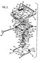
- Fig. 2 is an exploded, perspective view of the seat suspension in Fig. 1 ;
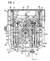
- Fig. 3 is a bottom view of the seat suspension of Fig. 1 in assembled form with portions of the base plate removed;
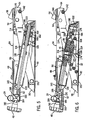
- Fig. 4 is a sectional view taken on line 4-4 of Fig. 3 showing the weight compensation mechanism in an initial setting
- Fig. 4A is a view like Fig. 4 showing a forward adjustment of the seat supporting frame and the manner in which the adjustment knob and the rod of the weight compensation adjusting mechanism move therewith;
- Fig. 5 is a view like Fig. 4 showing the weight compensation adjusting mechanism in a subsequent setting
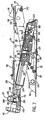
- Fig. 6 is a sectional view taken on line 6-6 of Fig. 3 showing the weight compensation adjustment mechanism in the setting of Fig. 4 ;
- Fig. 7 is a view like Fig. 6 showing the weight compensation adjustment mechanism in the setting of Fig. 5 ;
- Fig. 8 is an exploded view of the scissors linkage of the seat suspension
- Fig. 9 is a perspective view of Fig. 8 in an assembled condition.
- Fig. 10 is an exploded view of the seat back.
- a vehicle seat suspension embodying the present invention and generally identified by the reference numeral 10 is shown incorporated into the base or bottom portion of a vehicle seat 12 which is anchored to a floor 14 of the vehicle.
- the vehicle seat 12 includes a seat cushion 16 and a seat back 18 which may be either fixed or pivotally adjustable with respect to the seat cushion 16.
- a first adjusting mechanism 20 is provided to longitudinally adjust the position of the vehicle seat 12 relative to the floor 14 of the vehicle.
- a second adjusting mechanism 22 is provided to alter the resilient suspension of the vehicle seat 12 according to the weight of the seat occupant.
- the arrangement of components in the seat suspension 12 results in the seat having a relatively low profile desirable to purchasers of such suspensions.
- the vehicle suspension 10 includes a top frame 24, a bottom frame 26 and a substantially fully collapsible scissors linkage 28 interposed between the top frame 24 and the bottom frame 26.
- the first adjusting mechanism 20 is conveniently isolated in the top frame 24 and comprises a pair of adjustment channel assemblies 30.
- the second adjusting mechanism 22 is located between the top and bottom frames 24, 26, respectively, and comprises a suspension spring 32, a cam assembly 33 defined by a cam follower 34 and a cam 36, an adjustment paddle or strap 38, a weight adjusting arm assembly 40, a cylindrical coupling 41 with a throughhole 42, a clevis pin 43, and a long rod 44 attached to a weight adjustment knob 46.
- Top frame 24 is a generally U-shaped, steel tubular structure for supporting seat cushion 16 thereon.
- a forward portion of the tubular structure 24 includes a transverse support strap 48, and a pair of slide channels 50 extending between the strap 48 and the front of the tubular structure 24 on respective bottom surfaces thereof. Ends of the channels 50 define front and rear limits of travel for components of the scissors linkage 28 to be described later.
- An indicating and rod holding bracket 52 having a recess 53 ( Fig. 3 ) is welded to the front of the tubular structure 24.
- a rear portion of the tubular structure 24 includes a recessed, planar mounting bracket 54 having a pair of spaced apart, upstanding mounting walls 56 interconnected by a rear cross brace 58.
- the mounting walls 56 facilitate pivotal attachment of a seat back frame 60 ( Fig. 10 ) thereto.
- the seat back frame 60 has a support 57 for supporting a foam back 59 over which a cover 61 is slipped to form seat back 18.
- the spaced apart channel assemblies 30 are attached to a bottom surface of the mounting bracket 54 on opposed sides thereof, and are operably tied together by a connecting wire 62 in Fig. 3 .
- each top frame channel assembly 30 includes an elongated adjusting channel 64 which is C-shaped in cross section and has a bottom wall formed with a number of slots 66 along its length. Each channel 64 also has a front ear 68 and a rear ear 70 formed with aligned circular openings.
- a comb 72 which is U-shaped in cross section, has a bottom wall formed with a plurality of teeth 74, and also has a front tab 76 and a rear tab 78.
- Each adjusting channel 64 is juxtaposed relative to its comb 72 such that the teeth 74 of comb 72 are receivable in slots 66 of adjustment channel 64, and openings formed in ears 68, 70 are aligned with apertures formed in tabs 76, 78.
- an elongated release rod 80 extends through the aligned openings and apertures.
- the release rod 80 on the left side of the vehicle seat 12 includes an extension 82 which runs beyond the front end of the seat 12 and terminates in a handle 84 accessible to the seat occupant outside the left front corner of the seat 12.
- the forward end of each release rod 80 includes a U-shaped turning channel 86 fixed thereto which abuts front tab 76 on comb 72. As seen in Fig.
- each release rod 80 projects beyond rear tab 78, and is received in a wire eye 88 carrying connecting wire 62.
- a torsion latch spring 90 ( Fig. 2 ) surrounds a forward portion of release rod 80 and is interposed between front ear 68 of adjusting channel 64 and front tab 76 of comb 72. Each torsion latch spring 90 is positioned to normally retain teeth 74 of each comb 72 in the slots 66 of its respective adjusting channel 64.
- the bottom frame 26 is a generally H-shaped steel base plate 92 having bent side edges 94 which form opposite side channels 96. Holes 98 formed in the corners of base plate 92 can be used to receive studs (not shown) extending upwardly from the vehicle floor 14 and nuts (not shown) can be screwed onto the studs so as to fix the base plate 92 relative to the vehicle floor 14.
- the base plate 92 has a pair of mounting segments 100 carrying suitable fasteners 102 to enable a connection to a portion of the scissors linkage 28.
- the base plate 92 is also provided with a central opening 104 ( Fig. 6 ) which receives a nut 106 used to secure the base plate 92 with the suspension superstructure.
- top frame 24 and bottom frame 26 are connected one above the other in parallel by scissors linkage 28 formed by a pair of inner links 108, 110, and a pair of outer links 112, 114.
- the inner links 108, 110 are formed by the bent side portions of a generally rectangular inner arm assembly 116 having a steel support plate 118 and bent front and rear portions 120, 122, respectively.
- Fig. 3 shows that on one side of the inner arm assembly 116, a reinforced tube 124 extends between the respective front and rear portions 120, 122.
- an inner arm reinforcement tab 126 projects upwardly from the plate 118, and a pair of aligned openings 128 ( Fig.
- a protrusion 130 extends upwardly from the plate 118 and has a hole aligned with the openings.
- the protrusion 130 carries a rotatable bearing 131 through which the rod 44 is passed.
- the cylindrical coupling 41 and the clevis pin 43 also extend downward from the plate 118.
- a rear corner area of the plate 118 is cut out at 132 to accommodate a portion of the weight adjusting arm assembly 40.
- Inner link 108 has a coupling-nut 134 welded to it and the reinforcement tube 124, and extends laterally through and outside the link 108.
- the opposite inner link 110 has a coupling nut 136 welded to it and to the inner arm reinforcement tab 126, and extends laterally through and beyond the link 110.
- Forward ends of the inner links 108, 110 carry pins 138 for mounting a first pair of slide blocks 140 slidably received in the slide channels 50 at the front of top frame 24.
- Rearward ends of the inner links 108, 110 have holes and nuts (one being seen at 111 in Fig. 2 ) welded to the inner surfaces of the inner links 108, 110 to receive the fasteners 102 in the mounting segments 100 of base plate 92.
- the outer links 112, 114 are joined at rearward ends by a transfer shaft 142.
- the rearward ends of the outer links 112, 114 are provided with pins 144 for mounting adjusting blocks 146 slidably received in the adjustment channel assemblies 30 on the top frame 24.
- the forward ends of the outer links 112, 114 are equipped with pins 148 for mounting a second pair of slide blocks 150 which are slidably accommodated in the side channels 96 on bottom frame 26.
- a midportion of each outer link 112, 114 is operably connected to a midportion of each inner link 108, 110 by a bolt 152 threaded into one of the coupling nuts 134, 136.
- Figs. 2-7 illustrate the weight compensation adjustment mechanism 22.
- Cylindrical coupling 41 and clevis pin 43 extend vertically downwardly from the underside of formed inner arm plate 118.
- Coupling 41 passes through a notched hole 154 formed by a continuous wall 156 on a distal end of adjustment strap 38 in underlying contact with the plate 118.
- the peripheral size of the hole 154 is larger than the diameter of the coupling 41 so that the coupling 41 lies in spaced relationship to wall 156.
- a proximal end of the adjustment strap 38 is joined to the weight adjusting arm assembly 40.
- the assembly 40 has a pair of spaced apart arms 158 held together by a rivet 159 and defining a pair of bifurcated legs 160 between which a clevis nut 162 is rotatably mounted.
- the proximal end of the adjustment strap 38 is received between the arms 158 and retained by a clevis pin 164 and a cotter pin 166 such that there is freedom for relative movement between the adjustment strap 38 and the spaced apart arms 158.
- the arms 158 have two aligned holes for receiving the clevis pin 43 in order that the arms 158 may rotate thereon.
- the coupling 41 also passes through the cam 36, the cam follower 34 and at least a portion of the spring 32.
- the cam 36 is oriented into the notched hole 154 on the adjustment strap 38 such that a boss on the cam 36 aligns with the notch in the hole 154 to prevent rotational movement of the cam 36 relative to the adjustment strap 38.
- the cam 36 has a cavity so as to enable relative motion between the cam 36 and the coupling 41.
- the cam 36 contains a series of inclined wedges or ramps 168 engageable with complimentary ramped surfaces 170 on cam follower 34. Extending outwardly from the base of the cam follower 34 is a lip 172 which serves to seat small or upper end of the spring 32 that encircles the cam follower 34.
- the spring 32 includes a large or lower end which is seated against the base plate 92.
- Spring 32 is installed with a predetermined preload force which urges top frame 24 away from bottom frame 26.
- An upstop or fastener 174 is inserted through the coupling throughhole 42 and has a threaded end which is received in the nut 106 fitted into base plate 92 so as to hold together the scissors linkage 28, the adjuster strap 38, the weight adjustment arm assembly 40, the cam 36, the cam follower 34, the spring 32 and the base plate 92.
- the fastener 174 is threaded into the nut 106 for such a distance as to set the maximum distance between the seat 16 and the base plate 92. It should be appreciated that the fastener 174 passes through the neutral axis of the spring 32 and counteracts the load pressure thereof to allow lighter components in the suspension. By offsetting the load, these light weight components remain straight and functional. Use of the fastener 174 facilitates not placing the base plate 92 in a bending load.
- An adjuster screw 176 has external threads engageable with internal threads of a clevis nut 162, and has a forward end engaged against the bearing 131.
- the adjuster screw 176 has an internal hex 178 ( Fig. 4A ) which matingly receives a hex-shaped periphery of the long rod 44. Rotating the rod 44 will thus turn the adjuster screw 176 relative to the clevis nut 162 yet will allow the long rod 44 to freely slide through adjuster screw 176 when fore and aft adjustment is made.
- a jam nut 180 is threaded onto a rearward end of the adjuster screw 176 to act as a travel limitation device for the clevis nut 162.
- the long rod 44 is assembled into the adjuster screw 176 by passing the rod 44 through openings in the respective front and rear portions 120, 122 of the inner arm assembly 116 and the hole in the protrusion 130.
- the weight compensation knob 46 is mechanically fastened with a jam nut 182 to a forward end of the long rod 44 so as to transmit rotational motion.
- the long rod 44 is inserted into a hole formed in the bracket 52 at the front of the tubular structure 24.
- a spacer 184 and a spring pin 186 are located in such a way as to hold the knob 46 in a position relative to seat tube 24.
- a weight adjusting nut 188 is attached to the long rod 44 and has an extension 190 which projects into aligned grooves on the bracket 52 and an arm-like, weight adjusting indicator 192.
- the inner links 108, 110 and the outer links 112, 114 can be spaced from each other such that the first pair of slide blocks 140 are almost at the same level as the second pair of slide blocks 150 when scissors linkage 28 is substantially fully collapsed.
- the spring 32 is compressed by applying a heavy load on seat cushion 16 such that the spring coils are tightly bounded together upon one another. Arranging the links 108 through 114 and the spring 32 in a particular fashion will create additional clearance which places the seat 12 in a particularly low profile.
- top frame 24 holding seat cushion 16 can be selectively adjusted forwardly and rearwardly relative to scissors linkage 28 which is connected to the bottom frame 26.
- the long rod 44 of the weight compensation adjustment mechanism 22 slides freely through the interior 178 of the screw 176 as the fore and aft adjustment is made ( Fig. 4A ). This allows the adjustment knob 46 to travel with the front edge of the top frame 24 on which seat cushion 16 is mounted so that the knob 46 is always easily accessible to the seat occupant regardless of the seat fore and aft position.
- knob 46 As the knob 46 is rotated, these is provided a relative indication of the weight compensation adjustment.
- rotation of the knob 46 and nut 188 causes the arm-like indicator 192 to move relative to the recess 53 formed in the bracket 52.
- the amount of surface area of the indicator 192 seen through the recess 53 gives a visual indication to the seat occupant of the amount of the weight compensation adjustment.
Landscapes
- Engineering & Computer Science (AREA)
- Aviation & Aerospace Engineering (AREA)
- Transportation (AREA)
- Mechanical Engineering (AREA)
- Seats For Vehicles (AREA)
- Pharmaceuticals Containing Other Organic And Inorganic Compounds (AREA)
Claims (9)
- Sitzaufhängung mit geringer Bauhöhe (10), umfassend einen unteren Rahmen (26), welcher ausgelegt ist, um in einem Fahrzeug angebracht zu werden, einen oberen Rahmen (24), welcher über dem unteren Rahmen zum Tragen eines Sitzpolsters (16) und einer Sitzlehne (18) darauf angeordnet ist, ein im Wesentlichen zusammenklappbares Scherengestänge (28), welches zwischen dem unteren Rahmen und dem oberen Rahmen dazwischen eingebunden ist, um relative Bewegung ebendort dazwischen im Wesentlichen parallel zu ermöglichen, eine Trageanordnung, welche zwischen dem oberen Rahmen und dem unteren Rahmen angeordnet ist und eine Tragkraft aufweist, die den oberen Rahmen weg vom unteren Rahmen zwingt, einen ersten Anpassungsmechanismus (20), welcher im oberen Rahmen angeordnet ist, um ausgewählt Anpassung nach vorne und nach hinten des oberen Rahmens relativ zum unteren Rahmen zu ermöglichen, einen zweiten Anpassungsmechanismus (22), welcher zwischen dem oberen Rahmen und dem unterem Rahmen angeordnet ist, um ausgewählt eine Anpassung der Trageanordnung gemäß einem Körpergewicht eines auf dem Sitzpolster Sitzenden zu ermöglichen, indem eine horizontale Kraft, die auf eine Anpassungsplatte (38) wirkt, in eine vertikale Kraft umgesetzt wird, welche die Vorspannkraft der Trageanordnung beeinflusst, wobei die Anpassungsplatte mit einer Nocke (36) in Eingriff steht, wobei die horizontale Kraft die Anpassungsplatte mit der Nocke (36) gleitend bewegt und ein elastisches Element (32, 34) der Trageanordnung in eine vertikale Richtung verschiebt, dadurch gekennzeichnet, dass: der zweite Anpassungsmechanismus mit einem Anpassungsknopf (46) konstruiert und angeordnet ist, welcher sich nach vorne vom oberen Rahmen vor den Sitzpolster hin erstreckt und gemeinsam mit dem oberen Rahmen unbeeinflusst von der Vor- und Zurückanpassung des oberen Rahmens relativ zum unteren Rahmen bewegbar ist.
- Sitzaufhängung mit geringer Bauhöhe (10) nach Anspruch 1, wobei der zweite Anpassungsmechanismus (22) zwischen dem unteren Rahmen (26) und dem Scherengestänge (28) positioniert ist und eine Feder (32) umfasst, welche gegen den unteren Rahmen eingesetzt ist, wobei die Nocke (36) darüber und gegen die Feder angeordnet ist, einen Nockenmitläufer (34), welcher mit der Nocke in Eingriff steht, wobei die Anpassungsplatte (38) nicht drehbar mit dem Nockenmitläufer in Eingriff steht, ein Gewicht anpassender Armaufbau (40), welcher mit der Anpassungsplatte verbunden ist und zur Rotation auf dem Scherengestänge angebracht ist, eine Kupplung (41), welche vom Scherengestänge abhängend angebracht ist und durch die Anpassungsplatte, Nocke, Nockenmitläufer und wenigstens einen Abschnitt der Feder vorragt, eine Befestigung (174), welche die Kupplung mit dem unteren Rahmen zusammenfügt, und eine drehbare Anpassungsstange (44), welche sich zwischen dem Anpassungsknopf (46) und dem das Gewicht anpassenden Armzusammenbau erstreckt.
- Sitzaufhängung mit geringer Bauhöhe (10) nach Anspruch 2, wobei das Scherengestänge (28) ein drehbares Lager (131) trägt, durch welches die Anpassungsstange (44) hindurchgeht.
- Sitzaufhängung mit geringer Bauhöhe (10) nach Anspruch 3, wobei der das Gewicht anpassende Armzusammenbau (40) ein Paar von gegabelten Beinen (160) umfasst, zwischen denen eine Gabelkopfmutter (162) drehbar angebracht ist, wobei die Gabelkopfmutter ein Innengewinde aufweist, welches mit einem Außengewinde auf einer Anpassungsschraube (176) in Eingriff gebracht werden kann, die auf dem drehbaren Lager angebracht ist, wobei die Anpassungsschraube einen Innensechskant (178) zur passenden Aufnahme eines sechkantgeformten Umfangs der Anpassungsstange (44) aufweist, so dass die Rotation der Anpassungsstange die Anpassungsschraube relativ zur Gabelkopfmutter dreht und es der Anpassungsstange erlaubt, gleichzeitig durch den Innensechskant zu gleiten, wenn eine Anpassung nach vorne und hinten durchgeführt wird.
- Sitzaufhängung mit geringer Bauhöhe (10) nach Anspruch 4, wobei die Anpassungsplatte (38) mit den Gabelbeinen (160) verbunden ist und die Gabelbeine drehbar an einer Trägerplatte (118) des Scherengestänges befestigt sind, so dass die Rotation der Anpassungsstange (44) die Rotation der Anpassungsschraube (176) ermöglicht, was zur Bewegung der Gabelkopfmutter (162) und zur Rotation der Gabelbeine führt, um so eine horizontale Kraft an der Anpassungsplatte anzulegen, wobei die Bewegung der Anpassungsplatte die Nocke (36) relativ zum Nockenmitläufer (34) bewegt, um so die Komprimierung der Feder (32) zu verändern und eine angestrebte Dämpfung der Fahrterschütterungen für den auf dem Sitzpolster (16) Sitzenden bereit zu stellen.
- Sitzaufhängung mit geringer Bauhöhe (10) nach Anspruch 2, wobei der obere Rahmen (24) eine Halterung (52) zum Führen eines Gewichtsanpassungsindikators (192), welcher an der Anpassungsstange (44) angebracht ist, umfasst.
- Sitzaufhängung mit geringer Bauhöhe (10) nach Anspruch 6, wobei die Halterung (52) eine Ausnehmung (53) umfasst, welche den Indikator (192) umfasst, wobei die Rotation der Anpassungsstange (44) den Indikator sich relativ zur Ausnehmung bewegen lässt, wobei das Ausmaß des Oberflächenbereichs des Indikators, das durch die Ausnehmung sichtbar wird, eine visuelle Anzeige für den auf dem Sitzpolster (16) Sitzenden das Ausmaß der Gewichtskompensationsanpassung für den Sitzenden darstellt.
- Sitzaufhängung mit geringer Bauhöhe (10) nach Anspruch 1, wobei die Sitzlehne (18) schwenkbar auf dem oberen Rahmen (24) angebracht ist.
- Sitzaufhängung mit geringer Bauhöhe (10) nach Anspruch 2, wobei das Befestigungselement (174) durch eine neutrale Achse der Feder (32) hindurch geht und einem Belastungsdruck davon entgegen wirkt, um leichtere Komponenten in der Aufhängung zuzulassen und die Aufhängung gerade zu halten.
Applications Claiming Priority (2)
| Application Number | Priority Date | Filing Date | Title |
|---|---|---|---|
| US47761803P | 2003-06-11 | 2003-06-11 | |
| PCT/US2004/018093 WO2004110808A1 (en) | 2003-06-11 | 2004-06-08 | Low profile seat suspension |
Publications (2)
| Publication Number | Publication Date |
|---|---|
| EP1631474A1 EP1631474A1 (de) | 2006-03-08 |
| EP1631474B1 true EP1631474B1 (de) | 2009-12-09 |
Family
ID=33551737
Family Applications (1)
| Application Number | Title | Priority Date | Filing Date |
|---|---|---|---|
| EP04754647A Expired - Lifetime EP1631474B1 (de) | 2003-06-11 | 2004-06-08 | Sitzaufhängung mit niedrigem profil |
Country Status (9)
| Country | Link |
|---|---|
| US (1) | US7168671B2 (de) |
| EP (1) | EP1631474B1 (de) |
| KR (1) | KR101045453B1 (de) |
| CN (1) | CN100493951C (de) |
| AT (1) | ATE451267T1 (de) |
| BR (1) | BRPI0411194B1 (de) |
| DE (1) | DE602004024523D1 (de) |
| ES (1) | ES2337789T3 (de) |
| WO (1) | WO2004110808A1 (de) |
Families Citing this family (26)
| Publication number | Priority date | Publication date | Assignee | Title |
|---|---|---|---|---|
| US7032874B2 (en) * | 2003-11-21 | 2006-04-25 | Seats Incorporated | Suspension adjusting handle for a suspension system |
| US7571886B2 (en) * | 2004-05-03 | 2009-08-11 | John W. Carter | Bellcrank seat suspension apparatus |
| US20060045707A1 (en) * | 2004-06-15 | 2006-03-02 | Autolift Technology Inc. | Interchangeable multifunctional tow crossbar and accessories |
| US7413158B1 (en) * | 2004-11-08 | 2008-08-19 | Burer Peter J | Shock absorbing platform with dampening means |
| CN2756880Y (zh) * | 2004-12-11 | 2006-02-08 | 鸿富锦精密工业(深圳)有限公司 | 风扇固定装置 |
| US8413942B2 (en) * | 2008-04-11 | 2013-04-09 | Agco Corporation | Adjustable suspension system for a seat |
| DE102008056200B4 (de) * | 2008-11-06 | 2014-04-03 | Grammer Aktiengesellschaft | Scherengestell für einen Fahrzeugsitz, Fahrzeugsitz, insbesondere Kraftfahrzeugsitz, und Verfahren zum Herstellen eines Unterbaus eines Fahrzeugsitzes |
| US8585004B1 (en) | 2009-01-26 | 2013-11-19 | Atwood Mobile Products Llc | Air ride seat pedestal with independent height adjustment |
| DE102010026569B4 (de) | 2009-07-28 | 2014-03-27 | Grammer Aktiengesellschaft | Regelungseinrichtung zur Reduzierung einer Schwingungsbewegung einer federkraftbeaufschlagten schwingenden Vorrichtung |
| CN101716963B (zh) * | 2009-11-16 | 2012-11-28 | 济南吉利汽车有限公司 | 一种车辆独立悬挂系统中杆件的加载装置及方法 |
| DE102010010290B4 (de) * | 2010-03-04 | 2017-10-26 | Grammer Aktiengesellschaft | Fahrzeugsitz mit Gleitelement |
| US8016258B1 (en) | 2010-04-30 | 2011-09-13 | Seats, Inc. | Suspension adjustment mechanism for low suspension seat |
| DE102010035888B4 (de) | 2010-08-30 | 2018-05-09 | Grammer Ag | Fahrzeugsschwingungsvorrichtung |
| DE102010045114B4 (de) | 2010-09-13 | 2019-12-19 | Grammer Aktiengesellschaft | Verfahren zum Betreiben einer Fahrzeugdämpfungseinrichtung für einen Fahrzeugsitz / eine Fahrzeugkabine und Fahrzeugdämpfungseinrichtung für einen Fahrzeugsitz / eine Fahrzeugkabine |
| DE102010054752B4 (de) | 2010-09-13 | 2012-06-28 | Grammer Aktiengesellschaft | Gefederte Mehrpunktlagerung für Fahrzeuge mit Elastomerfederelement |
| DE102010048210B4 (de) | 2010-10-13 | 2021-09-16 | Grammer Aktiengesellschaft | Fahrzeugsitz mit Fluidfeder |
| DE102010051325B4 (de) | 2010-11-16 | 2020-11-26 | Grammer Aktiengesellschaft | Sitzfuß für einen Personensitz |
| DE102010055342B4 (de) | 2010-12-21 | 2015-03-26 | Grammer Aktiengesellschaft | Horizontale Sitzfedereinrichtung |
| DE102010055344A1 (de) | 2010-12-21 | 2012-06-21 | Grammer Aktiengesellschaft | Horizontale Sitzverstellung mit Stellglied |
| DE102011009530B4 (de) | 2011-01-26 | 2014-04-10 | Grammer Aktiengesellschaft | Fahrzeugschwingungsvorrichtung, Fahrzeugsitz oder Fahrgastzelle bzw. Fahrzeugkabine eines Fahrzeuges |
| DE102011015364B4 (de) | 2011-03-28 | 2012-10-11 | Grammer Aktiengesellschaft | Fahrzeugsitz mit einer Tragstruktur |
| US8561748B1 (en) | 2012-04-12 | 2013-10-22 | Seats, Inc. | Suspension configuration for a seat |
| US8690114B2 (en) | 2012-04-12 | 2014-04-08 | Seats, Inc. | Adjustable suspension system for off-road vehicle |
| US9789790B2 (en) * | 2014-10-03 | 2017-10-17 | Ford Global Technologies, Llc | Tuned flexible support member and flexible suspension features for comfort carriers |
| US11618355B2 (en) * | 2018-06-15 | 2023-04-04 | Milsco, Llc | Low profile adjustable vehicle seat mount assembly |
| CZ308489B6 (cs) * | 2019-07-21 | 2020-09-16 | Brano A.S. | Aretační zařízení |
Family Cites Families (14)
| Publication number | Priority date | Publication date | Assignee | Title |
|---|---|---|---|---|
| FR1475850A (fr) * | 1966-02-22 | 1967-04-07 | Sable Freres Int | Siège à position et suspension réglables pour véhicules industriels et analogues |
| GB1208051A (en) * | 1967-01-07 | 1970-10-07 | Eugenio Dalfiume | Improvements relating to seats |
| DE2233674C3 (de) * | 1972-07-08 | 1981-01-08 | Bremshey Ag, 5650 Solingen | Abgefederter Sitz, insbesondere Fahrzeugsitz |
| FR2208353A5 (de) * | 1972-11-28 | 1974-06-21 | Sable Freres Int | |
| US4228984A (en) * | 1978-11-13 | 1980-10-21 | Deere & Company | Vibration attenuator seat |
| US4384701A (en) * | 1980-10-01 | 1983-05-24 | Uop Inc. | Fore and aft adjustment and isolation assembly |
| US4448386A (en) * | 1981-12-01 | 1984-05-15 | Uop Inc. | Low profile resilient suspension for vehicle seat |
| US4880201A (en) * | 1987-12-03 | 1989-11-14 | Bostrom Seating, Inc. | Constant natural frequency, mechanical spring seat suspension |
| US4856763A (en) * | 1988-05-19 | 1989-08-15 | Sears Manufacturing Company | Mechanical seat suspension with concentric cam surfaces |
| US5794911A (en) | 1996-02-05 | 1998-08-18 | Milsco Manufacturing Company | Adjustable vehicle seat suspension |
| US5765802A (en) | 1996-08-02 | 1998-06-16 | H.O. Bostrom Company, Inc. | Low profile seat suspension |
| US6186467B1 (en) | 1999-05-06 | 2001-02-13 | Michigan Seat Company | Full seat adjustable suspension |
| CN2433118Y (zh) * | 2000-05-30 | 2001-06-06 | 朱丰 | 电动汽车座椅 |
| US6740271B2 (en) * | 2001-07-04 | 2004-05-25 | Man-Gu Sim | Board and board composition and manufacturing method thereof using crushed vegetational material and clay |
-
2004
- 2004-06-08 DE DE602004024523T patent/DE602004024523D1/de not_active Expired - Lifetime
- 2004-06-08 AT AT04754647T patent/ATE451267T1/de not_active IP Right Cessation
- 2004-06-08 EP EP04754647A patent/EP1631474B1/de not_active Expired - Lifetime
- 2004-06-08 WO PCT/US2004/018093 patent/WO2004110808A1/en not_active Ceased
- 2004-06-08 BR BRPI0411194-0A patent/BRPI0411194B1/pt not_active IP Right Cessation
- 2004-06-08 CN CNB2004800153463A patent/CN100493951C/zh not_active Expired - Fee Related
- 2004-06-08 KR KR1020057023565A patent/KR101045453B1/ko not_active Expired - Fee Related
- 2004-06-08 US US10/863,694 patent/US7168671B2/en not_active Expired - Lifetime
- 2004-06-08 ES ES04754647T patent/ES2337789T3/es not_active Expired - Lifetime
Also Published As
| Publication number | Publication date |
|---|---|
| US20050001133A1 (en) | 2005-01-06 |
| KR20060015752A (ko) | 2006-02-20 |
| ATE451267T1 (de) | 2009-12-15 |
| WO2004110808A1 (en) | 2004-12-23 |
| KR101045453B1 (ko) | 2011-06-30 |
| CN100493951C (zh) | 2009-06-03 |
| US7168671B2 (en) | 2007-01-30 |
| CN1798666A (zh) | 2006-07-05 |
| EP1631474A1 (de) | 2006-03-08 |
| BRPI0411194A (pt) | 2006-07-25 |
| BRPI0411194B1 (pt) | 2014-12-23 |
| ES2337789T3 (es) | 2010-04-29 |
| DE602004024523D1 (de) | 2010-01-21 |
Similar Documents
| Publication | Publication Date | Title |
|---|---|---|
| EP1631474B1 (de) | Sitzaufhängung mit niedrigem profil | |
| US5765802A (en) | Low profile seat suspension | |
| EP0873905B1 (de) | Verstellbare Fahrzeugsitzaufhängung | |
| EP2666667B1 (de) | Fahrzeugsitzscherenfederung mit integriertem, stabilisiertem Isolator | |
| US6719258B2 (en) | Shock and vibration isolation apparatus for motor vehicles seats | |
| US6000757A (en) | Vehicle seat adjuster | |
| EP2177394B1 (de) | Fahrzeugsitz | |
| US3999800A (en) | Vehicle seat | |
| US20030085600A1 (en) | Lumbar support device | |
| US7044559B2 (en) | Vehicle seat suspension force isolation apparatus | |
| US20040159763A1 (en) | Vehicle seating system with improved vibration isolation | |
| EP0342779B1 (de) | Aufhängungseinrichtung mit einem Nockenunterstützungselement | |
| US20140339747A1 (en) | Fore-aft vibration isolator | |
| US7571886B2 (en) | Bellcrank seat suspension apparatus | |
| EP1683443B1 (de) | Ottoman | |
| US6109584A (en) | Manual lock for seat adjuster | |
| US10076974B2 (en) | Modular forward and rearward seat position adjustment system, with integral vibration isolation system | |
| US20210061141A1 (en) | Vehicle seat assembly and return spring mechanism | |
| JP2001010378A (ja) | 車両用座席 | |
| JPH0739705Y2 (ja) | 車両用シートの減衰力可変機能付きサスペンション装置 | |
| JP2008254721A (ja) | 車両用シート | |
| JPH0346975Y2 (de) | ||
| JP2569437Y2 (ja) | サスペンションシート | |
| JP2566709Y2 (ja) | サスペンションシート | |
| JPH10181405A (ja) | シートサスペンション装置 |
Legal Events
| Date | Code | Title | Description |
|---|---|---|---|
| PUAI | Public reference made under article 153(3) epc to a published international application that has entered the european phase |
Free format text: ORIGINAL CODE: 0009012 |
|
| 17P | Request for examination filed |
Effective date: 20051128 |
|
| AK | Designated contracting states |
Kind code of ref document: A1 Designated state(s): AT BE BG CH CY CZ DE DK EE ES FI FR GB GR HU IE IT LI LU MC NL PL PT RO SE SI SK TR |
|
| DAX | Request for extension of the european patent (deleted) | ||
| 17Q | First examination report despatched |
Effective date: 20081008 |
|
| GRAP | Despatch of communication of intention to grant a patent |
Free format text: ORIGINAL CODE: EPIDOSNIGR1 |
|
| GRAS | Grant fee paid |
Free format text: ORIGINAL CODE: EPIDOSNIGR3 |
|
| GRAA | (expected) grant |
Free format text: ORIGINAL CODE: 0009210 |
|
| AK | Designated contracting states |
Kind code of ref document: B1 Designated state(s): AT BE BG CH CY CZ DE DK EE ES FI FR GB GR HU IE IT LI LU MC NL PL PT RO SE SI SK TR |
|
| REG | Reference to a national code |
Ref country code: GB Ref legal event code: FG4D |
|
| REG | Reference to a national code |
Ref country code: CH Ref legal event code: EP |
|
| REG | Reference to a national code |
Ref country code: IE Ref legal event code: FG4D |
|
| REF | Corresponds to: |
Ref document number: 602004024523 Country of ref document: DE Date of ref document: 20100121 Kind code of ref document: P |
|
| REG | Reference to a national code |
Ref country code: NL Ref legal event code: VDEP Effective date: 20091209 |
|
| REG | Reference to a national code |
Ref country code: ES Ref legal event code: FG2A Ref document number: 2337789 Country of ref document: ES Kind code of ref document: T3 |
|
| PG25 | Lapsed in a contracting state [announced via postgrant information from national office to epo] |
Ref country code: SE Free format text: LAPSE BECAUSE OF FAILURE TO SUBMIT A TRANSLATION OF THE DESCRIPTION OR TO PAY THE FEE WITHIN THE PRESCRIBED TIME-LIMIT Effective date: 20091209 Ref country code: FI Free format text: LAPSE BECAUSE OF FAILURE TO SUBMIT A TRANSLATION OF THE DESCRIPTION OR TO PAY THE FEE WITHIN THE PRESCRIBED TIME-LIMIT Effective date: 20091209 |
|
| PG25 | Lapsed in a contracting state [announced via postgrant information from national office to epo] |
Ref country code: SI Free format text: LAPSE BECAUSE OF FAILURE TO SUBMIT A TRANSLATION OF THE DESCRIPTION OR TO PAY THE FEE WITHIN THE PRESCRIBED TIME-LIMIT Effective date: 20091209 Ref country code: PL Free format text: LAPSE BECAUSE OF FAILURE TO SUBMIT A TRANSLATION OF THE DESCRIPTION OR TO PAY THE FEE WITHIN THE PRESCRIBED TIME-LIMIT Effective date: 20091209 |
|
| PG25 | Lapsed in a contracting state [announced via postgrant information from national office to epo] |
Ref country code: AT Free format text: LAPSE BECAUSE OF FAILURE TO SUBMIT A TRANSLATION OF THE DESCRIPTION OR TO PAY THE FEE WITHIN THE PRESCRIBED TIME-LIMIT Effective date: 20091209 |
|
| PG25 | Lapsed in a contracting state [announced via postgrant information from national office to epo] |
Ref country code: BG Free format text: LAPSE BECAUSE OF FAILURE TO SUBMIT A TRANSLATION OF THE DESCRIPTION OR TO PAY THE FEE WITHIN THE PRESCRIBED TIME-LIMIT Effective date: 20100309 Ref country code: EE Free format text: LAPSE BECAUSE OF FAILURE TO SUBMIT A TRANSLATION OF THE DESCRIPTION OR TO PAY THE FEE WITHIN THE PRESCRIBED TIME-LIMIT Effective date: 20091209 Ref country code: RO Free format text: LAPSE BECAUSE OF FAILURE TO SUBMIT A TRANSLATION OF THE DESCRIPTION OR TO PAY THE FEE WITHIN THE PRESCRIBED TIME-LIMIT Effective date: 20091209 Ref country code: NL Free format text: LAPSE BECAUSE OF FAILURE TO SUBMIT A TRANSLATION OF THE DESCRIPTION OR TO PAY THE FEE WITHIN THE PRESCRIBED TIME-LIMIT Effective date: 20091209 Ref country code: PT Free format text: LAPSE BECAUSE OF FAILURE TO SUBMIT A TRANSLATION OF THE DESCRIPTION OR TO PAY THE FEE WITHIN THE PRESCRIBED TIME-LIMIT Effective date: 20100409 |
|
| PG25 | Lapsed in a contracting state [announced via postgrant information from national office to epo] |
Ref country code: SK Free format text: LAPSE BECAUSE OF FAILURE TO SUBMIT A TRANSLATION OF THE DESCRIPTION OR TO PAY THE FEE WITHIN THE PRESCRIBED TIME-LIMIT Effective date: 20091209 Ref country code: CZ Free format text: LAPSE BECAUSE OF FAILURE TO SUBMIT A TRANSLATION OF THE DESCRIPTION OR TO PAY THE FEE WITHIN THE PRESCRIBED TIME-LIMIT Effective date: 20091209 Ref country code: BE Free format text: LAPSE BECAUSE OF FAILURE TO SUBMIT A TRANSLATION OF THE DESCRIPTION OR TO PAY THE FEE WITHIN THE PRESCRIBED TIME-LIMIT Effective date: 20091209 |
|
| PLBE | No opposition filed within time limit |
Free format text: ORIGINAL CODE: 0009261 |
|
| STAA | Information on the status of an ep patent application or granted ep patent |
Free format text: STATUS: NO OPPOSITION FILED WITHIN TIME LIMIT |
|
| PG25 | Lapsed in a contracting state [announced via postgrant information from national office to epo] |
Ref country code: CY Free format text: LAPSE BECAUSE OF FAILURE TO SUBMIT A TRANSLATION OF THE DESCRIPTION OR TO PAY THE FEE WITHIN THE PRESCRIBED TIME-LIMIT Effective date: 20091209 Ref country code: GR Free format text: LAPSE BECAUSE OF FAILURE TO SUBMIT A TRANSLATION OF THE DESCRIPTION OR TO PAY THE FEE WITHIN THE PRESCRIBED TIME-LIMIT Effective date: 20100310 |
|
| 26N | No opposition filed |
Effective date: 20100910 |
|
| PG25 | Lapsed in a contracting state [announced via postgrant information from national office to epo] |
Ref country code: DK Free format text: LAPSE BECAUSE OF FAILURE TO SUBMIT A TRANSLATION OF THE DESCRIPTION OR TO PAY THE FEE WITHIN THE PRESCRIBED TIME-LIMIT Effective date: 20091209 Ref country code: MC Free format text: LAPSE BECAUSE OF NON-PAYMENT OF DUE FEES Effective date: 20100630 |
|
| REG | Reference to a national code |
Ref country code: CH Ref legal event code: PL |
|
| PG25 | Lapsed in a contracting state [announced via postgrant information from national office to epo] |
Ref country code: LI Free format text: LAPSE BECAUSE OF NON-PAYMENT OF DUE FEES Effective date: 20100630 Ref country code: IE Free format text: LAPSE BECAUSE OF NON-PAYMENT OF DUE FEES Effective date: 20100608 Ref country code: CH Free format text: LAPSE BECAUSE OF NON-PAYMENT OF DUE FEES Effective date: 20100630 |
|
| PG25 | Lapsed in a contracting state [announced via postgrant information from national office to epo] |
Ref country code: HU Free format text: LAPSE BECAUSE OF FAILURE TO SUBMIT A TRANSLATION OF THE DESCRIPTION OR TO PAY THE FEE WITHIN THE PRESCRIBED TIME-LIMIT Effective date: 20100610 Ref country code: LU Free format text: LAPSE BECAUSE OF NON-PAYMENT OF DUE FEES Effective date: 20100608 |
|
| REG | Reference to a national code |
Ref country code: FR Ref legal event code: PLFP Year of fee payment: 13 |
|
| PGFP | Annual fee paid to national office [announced via postgrant information from national office to epo] |
Ref country code: ES Payment date: 20160628 Year of fee payment: 13 Ref country code: GB Payment date: 20160523 Year of fee payment: 13 |
|
| PGFP | Annual fee paid to national office [announced via postgrant information from national office to epo] |
Ref country code: FR Payment date: 20160616 Year of fee payment: 13 Ref country code: TR Payment date: 20160529 Year of fee payment: 13 |
|
| PGFP | Annual fee paid to national office [announced via postgrant information from national office to epo] |
Ref country code: IT Payment date: 20160621 Year of fee payment: 13 Ref country code: DE Payment date: 20160629 Year of fee payment: 13 |
|
| REG | Reference to a national code |
Ref country code: DE Ref legal event code: R119 Ref document number: 602004024523 Country of ref document: DE |
|
| GBPC | Gb: european patent ceased through non-payment of renewal fee |
Effective date: 20170608 |
|
| REG | Reference to a national code |
Ref country code: FR Ref legal event code: ST Effective date: 20180228 |
|
| PG25 | Lapsed in a contracting state [announced via postgrant information from national office to epo] |
Ref country code: GB Free format text: LAPSE BECAUSE OF NON-PAYMENT OF DUE FEES Effective date: 20170608 Ref country code: DE Free format text: LAPSE BECAUSE OF NON-PAYMENT OF DUE FEES Effective date: 20180103 |
|
| PG25 | Lapsed in a contracting state [announced via postgrant information from national office to epo] |
Ref country code: FR Free format text: LAPSE BECAUSE OF NON-PAYMENT OF DUE FEES Effective date: 20170630 Ref country code: IT Free format text: LAPSE BECAUSE OF NON-PAYMENT OF DUE FEES Effective date: 20170608 |
|
| REG | Reference to a national code |
Ref country code: ES Ref legal event code: FD2A Effective date: 20181114 |
|
| PG25 | Lapsed in a contracting state [announced via postgrant information from national office to epo] |
Ref country code: ES Free format text: LAPSE BECAUSE OF NON-PAYMENT OF DUE FEES Effective date: 20170609 |
|
| PG25 | Lapsed in a contracting state [announced via postgrant information from national office to epo] |
Ref country code: TR Free format text: LAPSE BECAUSE OF NON-PAYMENT OF DUE FEES Effective date: 20170608 |