EP0913633A2 - Gasbrenner mit einem Brennkörper sowie einer Zünd- und/oder einer Überwachungsvorrichtung - Google Patents
Gasbrenner mit einem Brennkörper sowie einer Zünd- und/oder einer Überwachungsvorrichtung Download PDFInfo
- Publication number
- EP0913633A2 EP0913633A2 EP98120390A EP98120390A EP0913633A2 EP 0913633 A2 EP0913633 A2 EP 0913633A2 EP 98120390 A EP98120390 A EP 98120390A EP 98120390 A EP98120390 A EP 98120390A EP 0913633 A2 EP0913633 A2 EP 0913633A2
- Authority
- EP
- European Patent Office
- Prior art keywords
- ignition
- gas burner
- transmission part
- monitoring device
- holder
- Prior art date
- Legal status (The legal status is an assumption and is not a legal conclusion. Google has not performed a legal analysis and makes no representation as to the accuracy of the status listed.)
- Withdrawn
Links
Images

Classifications
-
- F—MECHANICAL ENGINEERING; LIGHTING; HEATING; WEAPONS; BLASTING
- F23—COMBUSTION APPARATUS; COMBUSTION PROCESSES
- F23D—BURNERS
- F23D14/00—Burners for combustion of a gas, e.g. of a gas stored under pressure as a liquid
- F23D14/46—Details
-
- F—MECHANICAL ENGINEERING; LIGHTING; HEATING; WEAPONS; BLASTING
- F23—COMBUSTION APPARATUS; COMBUSTION PROCESSES
- F23D—BURNERS
- F23D14/00—Burners for combustion of a gas, e.g. of a gas stored under pressure as a liquid
- F23D14/46—Details
- F23D14/72—Safety devices, e.g. operative in case of failure of gas supply
- F23D14/725—Protection against flame failure by using flame detection devices
-
- F—MECHANICAL ENGINEERING; LIGHTING; HEATING; WEAPONS; BLASTING
- F23—COMBUSTION APPARATUS; COMBUSTION PROCESSES
- F23D—BURNERS
- F23D2207/00—Ignition devices associated with burner
Definitions
- the invention relates to a gas burner with a burner body and one Ignition and / or monitoring device.
- Such a gas burner is known (DE-GM 72 45 516).
- This burner points a rust-shaped burner body designed as a lamella block.
- the combustion of the fuel gas takes place instead of.
- an ignition device used in order to ignite the fuel gas at the start of combustion.
- the combustion controlled by a monitoring device.
- the ignition and monitoring device are placed in places where there is a strong one Flame forms, or where quickly when igniting the fuel gas a strong one Fuel gas flow is present.
- the ignition and monitoring device are for this reason often not easily accessible.
- the burner body must then be expensive be disassembled if the ignition or monitoring device fails occurs.
- the fixation can thus be user-friendly in an easily accessible place apart from the ignition or control of the combustion Monitoring device can be made. With the transmission part can also be locked in inaccessible places within the Burner housing are operated. This is also favorable for maintenance.
- the transmission part is rotatably mounted about a pivot axis that the Lock coupled to the transmission part at a distance from the pivot axis is, and that the locking due to a pivoting of the transmission part in active connection or out of active connection with the ignition or Monitoring device can be brought.
- the pivoting of the transmission part can even in very confined spaces be ensured so that the size of the gas burner is not being affected.
- this consists of a wire material. It is therefore inexpensive to manufacture.
- a possible variant of the invention is characterized in that the ignition and / or Monitoring device are inserted into a holder, and that the fastening device is coupled to the holder, the Locking is adjustable relative to the bracket. For mounting the ignition or As a result, the monitoring device can initially be fixed in the holder and then be locked with the fastening device.
- the holder preferably has a plug-in projection which corresponds to one trained plug receptacle of the ignition and / or monitoring device is introduced.
- the Plug connection a secure connection of the ignition or monitoring device on the gas burner. This enables that even in any transport position guarantees the captivity of the ignition or monitoring device is.
- a positive connection is expediently provided between the ignition and / or monitoring device and holder.
- a possible variant of the invention is characterized in that the burner body is held in a combustion chamber that the ignition and / or monitoring device in the area towards the depth of the combustion chamber extending side of the burner body is arranged, and that the transmission part is led to the front of the burner body.
- the ignition or monitoring device can also be safely assembled and disassembled when the burner housing until it comes close to the burner body.
- On the front of the gas burner can be designed as a handle Control element coupled to the transmission part and for fixing the ignition or Monitoring device fixed by means of a fastener be.
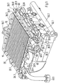
- the base part 50 essentially takes over the function of the gas supply line to a burner body 10.
- the base part 50 is made up of several gas ducts 50.1 enforced.
- the gas guides 50.1 face the front of the gas burner Gas inlet openings. Opposite this is a manifold 50.2 arranged.
- the distributor pipe 50.2 is fastened to the base part 50 and connectable to a gas supply.
- the distributor pipe 50.2 is in the Distance to the gas inlet openings of the gas guides 50.1 kept. In order to the gas flows through an air gap to the gas ducts 50.1 and mixes deal with the ambient air. The resulting mixture then flows to the burner body 10 as fuel gas.
- the burner body 10 is a lamella block educated.
- the liquid heat exchanger 40 can by means of an inlet 40.1 and an outlet 40.2 be connected to a circulatory system.
- the burner body 10 is surrounded by a frame 20.
- the frame 20 is composed of four profile pieces 20.1, 20.2, 20.3.
- the profile pieces 20.1, 20.2, 20.3 cover the burner body 10 laterally. Furthermore, the profile pieces wear 20.1, 20.2, 20.3 a collar covering the surface of the torch body 10 towers.
- the fastening sections 20.4 are bent in one piece from the respective end-side lamella of the burner body 10 and serve to hold brackets 70 and 80.
- To fix the brackets 70, 80 a flat connection surface is provided, into which an opening 20.5 is incorporated. At this opening 20.5, the bracket 70, 80 riveted, for example.
- a projection 20.6 of the mounting portion 20.4 in shape bent a nose.
- bracket 70, 80 The design and function of the bracket 70, 80 is below 2a to 3b explained in more detail.
- a bracket 70 is shown on the right side of the burner body 10 (see FIG. 1) is arranged. It serves to accommodate an ignition device 30.1.
- the bracket 70 has a connecting plate 70.1, the an anti-rotation lock 70.2 is equipped.
- the anti-rotation lock 70.2 is as slot-shaped recess worked into the connection plate 70.1.
- Below the anti-rotation device 70.2 is a mounting receptacle 70.11 in the connection plate 70.1 drilled.
- the anti-rotation device 70.2 with the projection 20.6 brought into active connection. Then a positive connection can be made via the Fastening receptacle 70.11 and breakthrough 20.5 are made.
- Transition sections 70.3 are bent laterally from the connecting plate 70.1. These each carry a plug 70.4. Maintenance of the lugs 70.4 the transition sections 70.3 merge into legs 70.5, 70.9. This in turn are provided with pivot bearings 70.6,70.10. Here is the pivot bearing 70.10 formed as a slot that from the bottom of the bracket 70 forth is accessible; the rotary bearing 70.6, however, turns out to be a through hole represents.
- connection plate 70.1 From the downward side of the connection plate 70.1 is in one piece Support 70.8 angled.
- the ignition device 30.1 can be placed on this become.
- the ignition device 30.1 is also with lateral plug receptacles provided, in which the plug-in lugs 70.4 are inserted.
- a fastening device 90 To fix the Ignition device 30.1 is a fastening device 90, as used in individual can be seen from Fig. 2b.
- This fastening device 90 is as Wire bracket designed. It has an operating element 90.8 at one end that forms a handle together with a leg 90.7.
- the leg 90.7 is at right angles to a transmission part 90.6. From the transmission part 90.6 is bent a leg 90.5, which carries a lock 90.4. Parallel a further leg 90.3 is connected to the leg 90.5 at the locking means 90.4.
- the fastening device is in alignment with the transmission part 90.6 90 a bearing piece 90.2, which ends in a hook 90.1.
- the fastening device 90 can be easily connected to the holder 70 get connected.
- the hook 90.1 is inserted into the pivot bearing 70.6 that the bearing piece 90.2 comes to rest in this.
- the transmission part 90.6 on its area facing the leg 90.5 be pivoted into the pivot bearing 70.10.
- the transmission part 90.6 and the bearing piece 90.2 thus form a common axis of rotation about which the Fastening device 90 can be pivoted.
- the lock can be 90.4 adjust eccentrically. With the lock 90.4 can also the ignition device 30.1 are clamped in the holder 70.
- the arrangement of the holder 70 on the gas burner can be seen in more detail in FIG. 1 become. It can be seen from this illustration that the holder 70 arranged at a not easily accessible side position on the profile piece 20.2 is.
- the ignition device 30.1 can still be used in the event of damage easy to replace.
- the control element 90.8 by means of Transmission part 90.6 held on the front of the gas burner.
- the transmission part 90.6 is held at the end in a further pivot bearing 20.9.
- the Rotary bearing 20.9 is placed in a tab 20.7, which over the profile piece 20.2 protrudes and is part of the profile piece 20.1.
- the control element 90.8 can be via a Fasteners 20.8 to be fixed on the front profile piece 20.1.
- the monitoring device 30.2 is fastened in a comparable manner. As can be seen from FIG. 3a, the holder 80 is based on the geometry the monitoring device 30.2 adapted.
- the bracket 80 again has a flat connecting plate 80.1, which an anti-rotation device 80.3 and an attachment receptacle 80.6 with the attachment section 20.4 can be connected.
- connection plate 80.1 From the connection plate 80.1 are two legs 80.7 which are parallel to one another, Turned 80.11. Furthermore, the connection plate 80.1 carries a holding section 80.4 and a support 80.9. The monitoring device 30.2 can be placed on the holding section 80.4. A connection contact protrudes here Monitoring device 30.2 through a passage 80.10 of the support 80.9. The holding section 80.4 is provided with a recess 80.5 which the outer dimensions of the monitoring device 30.2 adapted is. A connector 80.2 is bent from the connection plate 80.1, which in a slot of the monitoring device 30.2 engages so that this is held axially immovable.
- a fastening device serves to finally fix the monitoring device 30.2 90, as shown in detail in Fig. 3b.
- This Fastening device is essentially identical to that which is shown in Fig. 2b is shown. Differences exist in that the transmission part 90.6 has a different length and that the hook 90.1 is not present.
- the fastening device 90 according to FIG. 3b is with its bearing piece 90.2 can be used in a rotary bearing 80.8 of the leg 80.7.
- the transmission part 90.6 is in turn mounted in the pivot bearing 20.9 of the tab 20.7.
Landscapes
- Engineering & Computer Science (AREA)
- Chemical & Material Sciences (AREA)
- Combustion & Propulsion (AREA)
- Mechanical Engineering (AREA)
- General Engineering & Computer Science (AREA)
- Feeding And Controlling Fuel (AREA)
- Gas Burners (AREA)
Abstract
Description
- Fig. 1
- in perspektivischer Seitenansicht eine Zusammenstellzeichnung eines Gasbrenners,
- Fig. 2a
- eine in Fig. 1 an der rechten Brennerseite befestigte Halterung,
- Fig. 2b
- eine an der Halterung gemäß Fig. 2a angekoppelte Befestigungsvorrichtung,
- Fig. 3a
- eine weitere Halterung, die an der linken Seite des Gasbrenners befestigt ist und
- Fig. 3b
- eine Befestigungsvorrichtung, die an der Halterung gemäß Fig. 3a angekoppelt ist.
Claims (9)
- Gasbrenner mit einem Brennerkörper sowie einer Zünd- und/oder einer Überwachungsvorrichtung, die im Bereich des Brennerkörpers angeordnet und mittels einer Befestigungsvorrichtung befestigt ist,
dadurch gekennzeichnet,daß die Befestigungsvorrichtung (90) eine Arretierung (90.4) aufweist, die mittels eines Übertragungsteils (90.6) bedienbar ist und die die Zünde- und/oder Überwachungsvorrichtung (30.1,30.2) festhält, unddaß an das Übertragungsteil (90.6) ein Bedienelement (90.8) angeschlossen ist, das an einer gut zugänglichen Stelle des Brennkörpers (10) angeordnet ist. - Gasbrenner nach Anspruch 1,
dadurch gekennzeichnet,daß das Übertragungsteil (90.6) um eine Schwenkachse drehbar gelagert ist,daß die Arretierung (90.4) im Abstand zu der Schwenkachse an das Übertragungsteil (90.6) angekoppelt ist, unddaß die Arretierung (90.4) infolge einer Verschwenkung des Übertragungsteils (90.6) in oder außer Wirkverbindung mit der Zünd- bzw. Überwachungsvorrichtung (30.1,30.2) bringbar ist. - Gasbrenner nach Anspruch 1,
dadurch gekennzeichnet,daß die Befestigungsvorrichtung (90) aus einem Drahtmaterial besteht,daß von den Bedienelement (90.8) das Übertragungsteil (90.6) abgewinkelt ist,daß von dem Übertragungsteil (90.6) ein Schenkel (90.5) abgebogen ist, der in die Arretierung (90.4) übergeht,daß parallel zu dem Schenkel (90.5) ein weiterer Schenkel (90.3) von der Arretierung (90.4) abgeht unddaß der weitere Schenkel (90.3) in ein Lagerstück (90.2) übergeht, das in Flucht mit dem Übertragungsteil (90.6) steht und zusammen mit diesem die Schwenkachse bildet. - Gasbrenner nach einem der Ansprüche 1 bis 3,
dadurch gekennzeichnet,daß die Zünd- und/oder Überwachungsvorrichtung (30.1,30.2) in jeweils eine Halterung (70,80) eingesetzt ist unddaß die Befestigungsvorrichtung (90) an die Halterung (70, 80) angekoppelt ist, gegenüber der die Arretierung (90.4) verstellbar ist. - Gasbrenner nach Anspruch 4,
dadurch gekennzeichnet,daß die Halterung (70,80) wenigstens einen Steckansatz (70.4, 80.2) aufweist, der in eine Steckaufnahme der Zünd- und/oder Überwachungseinrichtung (30.1,30.2) einführbar ist. - Gasbrenner nach Anspruch 4 oder 5,
dadurch gekennzeichnet,daß die Halterung (70,80) als separates Bauteil ausgebildet ist, das über einen Befestigungsabschnitt (20.4) mit dem Brennerkörper (10) verbunden ist. - Gasbrenner nach einem der Ansprüche 4 bis 6,
dadurch gekennzeichnet,daß die Zünd- bzw. Überwachungsvorrichtung (30.1,30.2) mittels der Befestigungsvorrichtung (90) formschlüssig in der Halterung (70,80) festlegbar ist. - Gasbrenner nach einem der Ansprüche 1 bis 7,
dadurch gekennzeichnet,daß der Brennerkörper (10) in einem Gasbrennergehäuse gehalten ist,daß die Zünd- und/oder Überwachungsvorrichtung (30.1,30.2) im Bereich einer, in Richtung der Tiefe des Gasbrennergehäuses verlaufenden Seite des Brennerkörpers (10) angeordnet ist unddaß das Übertragungsteil (90.6) zur Vorderseite des Brennerkörpers (10) geführt ist. - Gasbrenner nach einem der Ansprüche 1 bis 8,
dadurch gekennzeichnet,daß das Bedienelement (90.8) als Handgriff ausgebildet ist, der an der Vorderseite des Brennerkörpers (10) angeordnet und mittels eines Befestigungsmittels (20.8) festlegbar ist.
Applications Claiming Priority (2)
| Application Number | Priority Date | Filing Date | Title |
|---|---|---|---|
| DE1997147482 DE19747482C1 (de) | 1997-10-28 | 1997-10-28 | Gasbrenner mit einem Brennerkörper sowie einer Zünd- und/oder einer Überwachungsvorrichtung |
| DE19747482 | 1997-10-28 |
Publications (2)
| Publication Number | Publication Date |
|---|---|
| EP0913633A2 true EP0913633A2 (de) | 1999-05-06 |
| EP0913633A3 EP0913633A3 (de) | 1999-12-01 |
Family
ID=7846811
Family Applications (1)
| Application Number | Title | Priority Date | Filing Date |
|---|---|---|---|
| EP98120390A Withdrawn EP0913633A3 (de) | 1997-10-28 | 1998-10-28 | Gasbrenner mit einem Brennkörper sowie einer Zünd- und/oder einer Überwachungsvorrichtung |
Country Status (2)
| Country | Link |
|---|---|
| EP (1) | EP0913633A3 (de) |
| DE (1) | DE19747482C1 (de) |
Citations (2)
| Publication number | Priority date | Publication date | Assignee | Title |
|---|---|---|---|---|
| DE705262C (de) | 1936-08-22 | 1941-04-22 | Junkers & Co | UEberschlagzuendvorrichtung fuer gasbeheizte Geraete mit schwer zugaenglichem Brenner |
| DE7245516U (de) | 1973-04-19 | Junkers & Co Gmbh | Vorrichtung zum Zünden und Überwachen von Gasgeraten |
Family Cites Families (2)
| Publication number | Priority date | Publication date | Assignee | Title |
|---|---|---|---|---|
| JPS6080032A (ja) * | 1983-10-06 | 1985-05-07 | Matsushita Electric Ind Co Ltd | ガスコンロ |
| JP2589923B2 (ja) * | 1992-12-16 | 1997-03-12 | リンナイ株式会社 | こんろバーナ |
-
1997
- 1997-10-28 DE DE1997147482 patent/DE19747482C1/de not_active Expired - Fee Related
-
1998
- 1998-10-28 EP EP98120390A patent/EP0913633A3/de not_active Withdrawn
Patent Citations (2)
| Publication number | Priority date | Publication date | Assignee | Title |
|---|---|---|---|---|
| DE7245516U (de) | 1973-04-19 | Junkers & Co Gmbh | Vorrichtung zum Zünden und Überwachen von Gasgeraten | |
| DE705262C (de) | 1936-08-22 | 1941-04-22 | Junkers & Co | UEberschlagzuendvorrichtung fuer gasbeheizte Geraete mit schwer zugaenglichem Brenner |
Also Published As
| Publication number | Publication date |
|---|---|
| DE19747482C1 (de) | 1999-04-29 |
| EP0913633A3 (de) | 1999-12-01 |
Similar Documents
| Publication | Publication Date | Title |
|---|---|---|
| DE10038001B4 (de) | Sensoranordnung | |
| DE112014000513B4 (de) | Durchflussratensteuervorrichtung | |
| DE19747482C1 (de) | Gasbrenner mit einem Brennerkörper sowie einer Zünd- und/oder einer Überwachungsvorrichtung | |
| EP0924464A1 (de) | Verfahren zur Kühlung des Rostes von Verbrennungsanlagen und Verbrennungsrost | |
| EP0327135B1 (de) | Atmosphärischer Gasbrenner | |
| EP0617244B1 (de) | Luftheizgerät | |
| WO1994021970A1 (de) | Standkonsole für heizkörper | |
| DE102009035317B4 (de) | Vorrichtung zur Halterung eines Heizkörpers | |
| DE3736612A1 (de) | Vorrichtung zur befestigung von wendelrohrpatronen auf den spritzduesen von spritzwerkzeugen | |
| DE20112299U1 (de) | Ionisationselektrode | |
| DE2253542B2 (de) | ölbrenner mit Radialgebläse und Umlenkeinrichtung für Verbrennungsluft | |
| DE10038358C2 (de) | Gasbeheiztes Gargerät mit Zündsicherungsvorrichtung | |
| DE69835545T2 (de) | Sprühfeuchtwerk für eine Druckmaschine | |
| DE69901988T2 (de) | Kappe eines Zündbrenners für einen Heisswassererzeuger | |
| DE60114148T2 (de) | Brenner mit verlängerung des venturirohres | |
| DE60010565T2 (de) | Verfahren und Gerät zum Anschluss eines Heizkörpers in einer Heizungsanlage und zwei Schnellkupplungseinheiten für solch eine Anlage | |
| DE3127873C2 (de) | ||
| DE69008830T2 (de) | Positionierungs- und Zentrierungsvorrichtung für Pilotbrenner und -zünder an eine Einspritzleitung für Gasbrenner. | |
| DE19605541C2 (de) | Rückwandriegel für Möbel wie Schränke oder dergleichen | |
| DE60126728T2 (de) | Universales Thermoelement | |
| EP4660527A1 (de) | Doppelkammerrohrbrenner zum lösbaren einsetzen in portable gasgrills | |
| DE29813790U1 (de) | Schaltschrank | |
| DE9105059U1 (de) | Anschlußvorrichtung für einen Gasmesser | |
| DE2836168C3 (de) | Konsole zum Befestigen von Heizkörpern an einer Wand | |
| CH417365A (de) | Heizvorrichtung, insbesondere für Kraftfahrzeuge |
Legal Events
| Date | Code | Title | Description |
|---|---|---|---|
| PUAI | Public reference made under article 153(3) epc to a published international application that has entered the european phase |
Free format text: ORIGINAL CODE: 0009012 |
|
| AK | Designated contracting states |
Kind code of ref document: A2 Designated state(s): AT CH DE ES FR GB IT LI |
|
| AX | Request for extension of the european patent |
Free format text: AL;LT;LV;MK;RO;SI |
|
| PUAL | Search report despatched |
Free format text: ORIGINAL CODE: 0009013 |
|
| AK | Designated contracting states |
Kind code of ref document: A3 Designated state(s): AT BE CH CY DE DK ES FI FR GB GR IE IT LI LU MC NL PT SE |
|
| AX | Request for extension of the european patent |
Free format text: AL;LT;LV;MK;RO;SI |
|
| 17P | Request for examination filed |
Effective date: 20000602 |
|
| AKX | Designation fees paid |
Free format text: AT CH DE ES FR GB IT LI |
|
| 17Q | First examination report despatched |
Effective date: 20011109 |
|
| STAA | Information on the status of an ep patent application or granted ep patent |
Free format text: STATUS: THE APPLICATION IS DEEMED TO BE WITHDRAWN |
|
| 18D | Application deemed to be withdrawn |
Effective date: 20020320 |