EP1840472B1 - Gasherd - Google Patents
Gasherd Download PDFInfo
- Publication number
- EP1840472B1 EP1840472B1 EP07104433.3A EP07104433A EP1840472B1 EP 1840472 B1 EP1840472 B1 EP 1840472B1 EP 07104433 A EP07104433 A EP 07104433A EP 1840472 B1 EP1840472 B1 EP 1840472B1
- Authority
- EP
- European Patent Office
- Prior art keywords
- unit
- heat protection
- functional unit
- retaining
- cooking hob
- Prior art date
- Legal status (The legal status is an assumption and is not a legal conclusion. Google has not performed a legal analysis and makes no representation as to the accuracy of the status listed.)
- Active
Links
Images

Classifications
-
- F—MECHANICAL ENGINEERING; LIGHTING; HEATING; WEAPONS; BLASTING
- F24—HEATING; RANGES; VENTILATING
- F24C—DOMESTIC STOVES OR RANGES ; DETAILS OF DOMESTIC STOVES OR RANGES, OF GENERAL APPLICATION
- F24C3/00—Stoves or ranges for gaseous fuels
- F24C3/12—Arrangement or mounting of control or safety devices
- F24C3/126—Arrangement or mounting of control or safety devices on ranges
-
- F—MECHANICAL ENGINEERING; LIGHTING; HEATING; WEAPONS; BLASTING
- F24—HEATING; RANGES; VENTILATING
- F24C—DOMESTIC STOVES OR RANGES ; DETAILS OF DOMESTIC STOVES OR RANGES, OF GENERAL APPLICATION
- F24C3/00—Stoves or ranges for gaseous fuels
- F24C3/10—Arrangement or mounting of ignition devices
- F24C3/103—Arrangement or mounting of ignition devices of electric ignition devices
-
- F—MECHANICAL ENGINEERING; LIGHTING; HEATING; WEAPONS; BLASTING
- F24—HEATING; RANGES; VENTILATING
- F24C—DOMESTIC STOVES OR RANGES ; DETAILS OF DOMESTIC STOVES OR RANGES, OF GENERAL APPLICATION
- F24C15/00—Details
- F24C15/34—Elements and arrangements for heat storage or insulation
-
- F—MECHANICAL ENGINEERING; LIGHTING; HEATING; WEAPONS; BLASTING
- F24—HEATING; RANGES; VENTILATING
- F24C—DOMESTIC STOVES OR RANGES ; DETAILS OF DOMESTIC STOVES OR RANGES, OF GENERAL APPLICATION
- F24C15/00—Details
- F24C15/36—Protective guards, e.g. for preventing access to heated parts
Definitions
- the invention relates to gas stoves.
- Household appliance devices in particular for gas stoves, are known which comprise a functional unit and a heat protection unit.
- the functional unit and the heat protection unit are each individually attached to a base plate within the domestic appliance device by means of holding units.
- Such a home appliance device is from the US 3969656 known. It represents the closest prior art.
- the object of the invention is, in particular, to provide a gas stove with a generic household appliance device with improved properties with regard to simple and convenient installation and removal of a functional unit.
- the object is achieved by the features of patent claim 1, while advantageous refinements and developments of the invention can be found in the subclaims.
- the invention relates to a gas stove with a functional unit and a heat protection unit.
- the domestic appliance device of the gas cooker comprises two identical holding units, which are provided for fastening the functional unit to the heat protection unit, as a result of which particularly simple and convenient installation can be achieved.
- the functional unit together with the heat protection unit is particularly easy to mount on a base plate, since fastening to the base plate can be achieved either only with the functional unit and / or only with the heat protection unit.
- a particularly advantageous heat protection for the functional unit can be achieved by mounting the functional unit on the heat protection unit.
- a functional unit can be understood to mean a unit that is connected to a power supply and must therefore be protected in particular from heat, such as a computing unit and / or an ignition unit.
- the holding unit comprises a clamping unit, which advantageously enables the functional unit to be attached quickly and in particular in a space-saving manner to the heat protection unit, in particular if the holding unit comprises holding means formed by a clamping means that attach to the functional unit and / or are integrally formed on the heat protection unit.
- the clamping unit allows the functional unit to be arranged on the heat protection unit in a particularly stable and play-free manner.
- a clamping unit can be understood to mean a holding unit which achieves a holding function by means of a clamping force which acts between two holding means.
- the domestic appliance device advantageously comprises at least one further holding unit, which is provided for fastening the functional unit to a base plate.
- a structurally simple assembly of the functional unit together with the heat protection unit on the base plate can be achieved.
- the functional unit can also be mounted individually on the base plate and then the heat protection unit on the functional unit, so that the heat protection unit can also be installed and removed individually and independently of the functional unit.
- the further holding unit comprises a further clamping unit, and thus a stable, play-free and easily executable fastening of the functional unit to the base plate can be achieved.
- At least one clamping unit is preferably provided to be installed without tools and / or to be removed without tools.
- a holding means of the holding unit for fastening the functional unit to the heat protection unit and a holding means of the holding unit for fastening the functional unit on the base plate are arranged on different outer surfaces on the functional unit.
- the functional unit is advantageously arranged such that the base plate and the heat protection unit are located essentially on opposite outer surfaces of the functional unit, so that by arranging the holding means of the holding units on opposite outer surfaces of the functional unit, the functional unit can be attached to the base plate with little effort and can be reached on the heat protection unit.
- the functional unit can be formed by various units which appear useful to the person skilled in the art, but is an ignition unit according to the invention.
- the ignition unit can be arranged very close to the area of a gas burner and thereby largely protected from thermal radiation.
- An ignition unit can be understood to mean a unit which is intended to ignite the gas burners integrated in a gas stove at least partially automatically and which comprises at least one ignition element, in particular a spark plug.
- At least one spacer is arranged on at least one outer surface of the functional unit, so that an advantageous distance can be achieved between the functional unit and a component adjacent to the outer surface provided with the spacer, in particular if the spacer on the base plate and / or the outer surface facing the heat protection unit is arranged.
- the spacing means can create an advantageous intermediate space between the functional unit and the base plate and / or the heat protection unit, which can be used to cool the functional unit by allowing air to flow through the intermediate space and thereby effect a cooling effect on the functional unit.
- an electrically insulating air layer between the functional unit and the electrically conductive base plate can be achieved through the intermediate space.
- a spacer can be understood to mean a means by means of which two components or units can be arranged at a distance from one another.
- a holding means is advantageously arranged on the spacer, as a result of which a particularly stable, structurally simple fastening between the functional unit and the base plate and / or the heat protection unit can be achieved.
- a one-piece design of the spacer means with the holding means more Components, installation space, installation effort and costs can be saved.
- a holding means can be understood to mean various means which appear to be useful to the person skilled in the art, but particularly advantageously a means formed by an extension, which is intended to enter into a positive and / or non-positive connection with a corresponding means.
- At least one holding means is formed by an elongated hole, which forms a receiving area for the holding means formed by an extension, so that a positive and / or non-positive connection can be achieved with the extension.
- This can be achieved particularly advantageously by arranging at least one elongated hole in the heat protection unit.
- At least a partial area of the elongated hole be formed by an enlarged insertion area for inserting a holding means, as a result of which the holding means formed by an extension can be easily and quickly inserted into the elongated hole. It is particularly advantageous for the enlarged area in the longitudinal direction of the elongated hole to be followed by a tapered hole area, so that the holding means formed by an extension can be inserted comfortably into a holding area or clamping area.
- At least a portion of the elongated hole is advantageously formed by a holding area for clamping a holding means.
- the functional unit can be attached to the base plate and / or the heat protection unit in a particularly simple and space-saving manner, wherein a tensioning force can act on the holding means, in particular on the holding means formed by an extension, for fastening it within the holding area.
- a holding area can be understood to mean an area within the elongated hole whose width is smaller than a width of a holding element to be inserted. As a result, a tensioning force acts on the holding element inserted into the elongated hole, so that fastening can be achieved between the holding means and the component comprising the elongated hole.
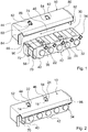
- FIG 1 shows a domestic appliance device with a functional unit formed by an ignition unit 34 and a heat protection unit 10.
- the domestic appliance device has two holding units 14, 16 (tension units) Figure 2 ).
- the identical holding units 14, 16 each have two corresponding holding means 22, 24, one of the two holding means 22, 24 being arranged on an outer surface 30 of the ignition unit 34 and the other holding means being introduced into the heat protection unit 10.
- the ignition unit 34 has an essentially cuboid design ( Figure 1 ) and is provided for igniting gas burners, not shown, in a gas stove, not shown.
- a housing 90 of the ignition unit 34 is formed from an insulating material.
- the ignition unit 34 has an opening 70 on an outer surface 68, which is provided for a power supply (not shown here).
- Two spacing means 36, 38, 40, 42 are arranged on the ignition unit 34 on two opposite outer surfaces 30, 32.
- the spacing means 36, 38, 40, 42 are formed in one piece with the ignition unit 34 or with the housing 90.
- the opposite outer surfaces 30, 32 of the ignition unit 34 are located itself on an upper side and a lower side of the ignition unit 34 ( Figures 1, 2 and 4 ).
- a main direction of extent 72 of the spacing means 36, 38, 40, 42 is in each case formed perpendicular to a main direction of extent 74 of the respective outer surface 30, 32 of the ignition unit 34 and is aligned parallel to the outer surface 30, 32 ( Figures 1 and 3 ).
- a spacing 76 of the individual spacing means 36, 38, 40, 42 extends perpendicular to the respective outer surface 30, 32, so that after the ignition unit 34 has been fastened to the heat protection unit 10 and to an in Figure 4 illustrated base plate 12, there is a distance between the ignition unit 34 and the heat protection unit 10 and between the ignition unit 34 and the base plate 12.
- the spacing means 36, 38, 40, 42 are each spaced apart from one another on one of the two outer surfaces 30, 32 of the ignition unit 34, so that, after the ignition unit 34 has been attached to the heat protection unit 10 or to the base plate 12, can be used for cooling, crosswise Channel-like interstices extending to the main direction of extent 74 of the ignition unit 34 arise.
- a cooling effect on the ignition unit 34 is achieved during operation by means of air circulation.
- the spacing means 36, 38, 40, 42 are each provided with a holding means 22, 24, 26, 28 formed by an extension, the spacing means 36, 38, 40, 42 and the holding means 22, 24, 26, 28 each being formed in one piece are.
- the holding means 22, 24, 26, 28 have circular cross-sectional areas which are designed to be constant in the direction of extension 78, 92 of the holding means 22, 24, 26, 28 which is perpendicular to the outer surface 30, 32 of the ignition unit 34.
- the heat protection unit 10 essentially represents a housing shell, which surrounds the ignition unit 34 on three outer surfaces, and has the task of shielding heat radiation and protecting the ignition unit 34 ( Figures 1 and 2 ).
- the housing shell of the heat protection unit 10 has a main extension surface 80 and two side surfaces 82, 84, the side surfaces 82, 84 adjoining the main extension surface 80 perpendicularly to the main extension surface 80 at an edge region of the main extension surface 80.
- the heat protection unit 10 has two holding means formed by elongated holes 44, 46, which are provided for fastening the ignition unit 34 to the heat protection unit 10.
- the main extension surface 80 of the heat protection unit 10 is formed parallel to the outer surface 30 of the ignition unit 34 in the assembled state.
- a main direction of extension 88 of the elongated holes 44, 46 is formed perpendicular to a main extension direction 74 of the main extension surface 80 of the heat protection unit 10, so that the elongated holes 44, 46 of the heat protection unit 10 and the spacing means 36, 38 of the ignition unit 34 are aligned in parallel in the assembled state ( Figure 1 ).
- the elongated holes 44, 46 each have an enlarged, circular insertion area 52, 54, a cross-sectional area of the insertion area 52, 54 being larger than a cross-sectional area of the holding means 22, 24 arranged on the ignition unit 34.
- Adjacent to the insertion area 52, 54 of the elongated holes 44, 46 are a tapering hole area and a holding area 60, 62, which has a smaller cross-sectional area than the insertion area 52, 54.
- the cross-sectional area of the holding area 60, 62 is smaller than the cross-sectional area of the holding means 22, 24, so that the holding means 22, 24 of the ignition unit 34 are introduced under a clamping force acting on the holding means 22, 24, the clamping force being the fastening between the ignition unit 34 and the heat protection unit 10.
- the insertion area 52, 54 and the holding area 60, 62 of an elongated hole 44, 46 are each arranged along the main extension direction 88 of the elongated hole 44, 46 such that an insertion movement of the holding means 22, 24 of the ignition unit 34 within the elongated hole 44, 46 parallel to the The main direction of extent 88 of the elongated hole 44, 46 is, so that the ignition unit 34 can be attached to the heat protection unit 10 particularly quickly and easily.
- the main extension surface 80 of the heat protection unit 10 comprises an edge region 86 which is inclined with respect to the main extension surface 80 and which has an inclination in the direction of the ignition unit 34 ( Figures 1 and 2 ).
- the domestic appliance device also comprises two further holding units 18, 20, which are formed by tensioning units and which enable fastening between the ignition unit 34 and the base plate 12 ( Figure 4 ).
- the holding unit 18, 20 in each case comprises an elongated hole 48, 50, which is made in the base plate 12, and the holding means 26, 28 formed by an extension, which is arranged on the outer surface 32 of the ignition unit 34.
- the holding means 26, 28 are located corresponding to the holding means 22, 24 on the spacer means 40, 42 formed integrally with the housing 90.
- the elongated holes 48, 50 of the base plate 12 have an enlarged, circular shape corresponding to the elongated holes 44, 46 of the heat protection unit 10 Insertion area 56, 58, a tapered hole area and a holding area 64, 66, wherein an arrangement of the insertion area 56, 58 and the holding area 64, 66 of the elongated holes 48, 50 within the base plate 12 an arrangement of the insertion area 52, 54 and the holding area 60, 62 within the heat protection unit 10.
- the elongated holes 48, 50 arranged in the base plate 12 are aligned parallel to the spacing means 40, 42.
- the elongated holes 48, 50 viewed in the assembled state — have a main direction of extension that differs from the elongated holes 44, 46; the main directions of extension could preferably be oriented perpendicular to one another.
- the ignition unit 34 can be assembled and disassembled or exchanged individually or together with the heat protection unit 10 particularly quickly and easily, in particular without tools.
Landscapes
- Engineering & Computer Science (AREA)
- Chemical & Material Sciences (AREA)
- Combustion & Propulsion (AREA)
- Mechanical Engineering (AREA)
- General Engineering & Computer Science (AREA)
- Baking, Grill, Roasting (AREA)
- Gas Burners (AREA)
- Feeding And Controlling Fuel (AREA)
- Cookers (AREA)
Description
- Die Erfindung betrifft Gasherde.
- Es sind Hausgerätevorrichtungen, insbesondere für Gasherde, bekannt, die eine Funktionseinheit und eine Hitzeschutzeinheit umfassen. Dabei sind die Funktionseinheit und die Hitzeschutzeinheit jeweils einzeln mittels Halteeinheiten an einer Grundplatte innerhalb der Hausgerätevorrichtung befestigt. Eine solche Hausgerätevorrichtung ist aus der
US 3969656 bekannt. Sie stellt den nächstliegenden Stand der Technik dar. - Die Aufgabe der Erfindung besteht insbesondere darin, einen Gasherd mit gattungsgemäßer Hausgerätevorrichtung mit verbesserten Eigenschaften hinsichtlich eines einfachen und komfortablen Ein- und Ausbaus einer Funktionseinheit bereitzustellen. Die Aufgabe wird erfindungsgemäß durch die Merkmale des Patentanspruchs 1 gelöst, während vorteilhafte Ausgestaltungen und Weiterbildungen der Erfindung den Unteransprüchen entnommen werden können.
- Die Erfindung geht aus von einem Gasherd mit einer Funktionseinheit und einer Hitzeschutzeinheit.
- Es wird vorgeschlagen, dass die Hausgerätevorrichtung des Gasherdes zwei baugleiche Halteeinheiten umfasst, die zum Befestigen der Funktionseinheit an der Hitzeschutzeinheit vorgesehen ist, wodurch eine besonders einfache und komfortable Montage erreicht werden kann. Zudem ist die Funktionseinheit zusammen mit der Hitzeschutzeinheit besonders einfach an eine Grundplatte montierbar, da hier eine Befestigung an die Grundplatte entweder nur mit der Funktionseinheit und/oder nur mit der Hitzeschutzeinheit erreicht werden kann. Zusätzlich kann durch die Montage der Funktionseinheit an die Hitzeschutzeinheit ein besonders vorteilhafter Hitzeschutz für die Funktionseinheit erzielt werden. In diesem Zusammenhang kann unter einer Funktionseinheit eine Einheit verstanden werden, die an eine Stromversorgung angeschlossen ist und daher insbesondere vor Hitze geschützt werden muss, wie beispielsweise eine Recheneinheit und/oder eine Zündeinheit.
- Des Weiteren wird vorgeschlagen, dass die Halteeinheit eine Spanneinheit umfasst, wodurch vorteilhaft ein schnelles und insbesondere ein Platz sparendes Anbringen der Funktionseinheit an der Hitzeschutzeinheit erreicht werden kann, und zwar insbesondere, wenn die Halteeinheit von einem Spannmittel gebildete Haltemittel umfasst, die an die Funktionseinheit und/oder an die Hitzeschutzeinheit einstückig angeformt sind. Zudem kann durch die Spanneinheit die Funktionseinheit besonders stabil und spielfrei an der Hitzeschutzeinheit angeordnet werden. Hierbei kann unter einer Spanneinheit eine Halteeinheit verstanden werden, die eine Haltefunktion durch eine Spannkraft, die zwischen zwei Haltemitteln wirkt, erreicht.
- Vorteilhafterweise umfasst die Hausgerätevorrichtung zumindest eine weitere Halteeinheit, die zum Befestigen der Funktionseinheit an einer Grundplatte vorgesehen ist. Hierdurch kann eine konstruktiv einfache Montage der Funktionseinheit zusammen mit der Hitzeschutzeinheit an der Grundplatte erreicht werden. Ferner kann die Funktionseinheit auch einzeln an der Grundplatte und danach die Hitzeschutzeinheit an der Funktionseinheit montiert werden, so dass die Hitzeschutzeinheit auch einzeln und unabhängig von der Funktionseinheit ein- und ausgebaut werden kann.
- Besonders vorteilhaft ist es, wenn die weitere Halteeinheit eine weitere Spanneinheit umfasst und somit eine stabile, spielfreie und einfach ausführbare Befestigung der Funktionseinheit an der Grundplatte erreicht werden kann. Vorzugsweise ist zumindest eine Spanneinheit dazu vorgesehen, werkzeuglos montiert und/oder werkzeuglos demontiert zu werden.
- In einer weiteren Ausgestaltung der Erfindung wird vorgeschlagen, dass ein Haltemittel der Halteeinheit zur Befestigung der Funktionseinheit an der Hitzeschutzeinheit und ein Haltemittel der Halteeinheit zur Befestigung der Funktionseinheit an der Grundplatte an unterschiedlichen Außenflächen an der Funktionseinheit angeordnet sind. Hierdurch kann ein besonders einfacher und vorteilhafter Einbau oder Ausbau der Funktionseinheit und/oder der Hitzeschutzeinheit erreicht werden, da unterschiedliche Außenflächen der Funktionseinheit der Hitzeschutzeinheit und der Grundplatte zugewandt sind. Die Befestigung der Funktionseinheit an der Grundplatte kann somit unabhängig von der Befestigung der Funktionseinheit an der Hitzeschutzeinheit erreicht werden.
- Zudem ist die Funktionseinheit vorteilhaft so angeordnet, dass sich die Grundplatte und die Hitzeschutzeinheit im Wesentlichen an gegenüberliegenden Außenflächen der Funktionseinheit befinden, so dass durch eine Anordnung der Haltemittel der Halteeinheiten an gegenüberliegenden Außenflächen der Funktionseinheit eine mit wenig Aufwand durchführbare Befestigung der Funktionseinheit an der Grundplatte und an der Hitzeschutzeinheit erreicht werden kann.
- Die Funktionseinheit kann von verschiedenen, dem Fachmann als sinnvoll erscheinenden Einheiten gebildet sein, ist jedoch erfindungsgemäß eine Zündeinheit. Die Zündeinheit kann in einer besonders zweckmäßigen Weise sehr nahe in dem Bereich eines Gasbrenners und dabei weitestgehend von Wärmestrahlung geschützt angeordnet werden. Dabei kann unter einer Zündeinheit eine Einheit verstanden werden, die dazu vorgesehen ist, die in einem Gasherd integrierten Gasbrenner zumindest teilautomatisch zu zünden, und die zumindest ein Zündelement, insbesondere eine Zündkerze, umfasst.
- Zudem wird vorgeschlagen, dass zumindest an einer Außenfläche der Funktionseinheit zumindest ein Abstandsmittel angeordnet ist, so dass zwischen der Funktionseinheit und einem an die mit dem Abstandsmittel versehene Außenfläche angrenzenden Bauteil ein vorteilhafter Abstand erreicht werden kann, insbesondere wenn das Abstandsmittel an der der Grundplatte und/oder der Hitzeschutzeinheit zugewandten Außenfläche angeordnet ist. Es kann durch das Abstandsmittel ein vorteilhafter Zwischenraum zwischen der Funktionseinheit und der Grundplatte und/oder der Hitzeschutzeinheit geschaffen werden, der zu einer Kühlung der Funktionseinheit verwendet werden kann, indem Luft durch den Zwischenraum strömen und dabei einen kühlenden Effekt an der Funktionseinheit bewirken kann. Zudem kann durch den Zwischenraum eine elektrische isolierende Luftschicht zwischen der Funktionseinheit und der elektrisch leitenden Grundplatte erreicht werden. In diesem Zusammenhang kann unter einem Abstandsmittel ein Mittel verstanden werden, mit Hilfe dessen zwei Bauteile bzw. Einheiten beabstandet zueinander angeordnet werden können.
- Vorteilhafterweise ist auf dem Abstandsmittel ein Haltemittel angeordnet, wodurch eine besonders stabile, konstruktiv einfache Befestigung zwischen der Funktionseinheit und der Grundplatte und/oder der Hitzeschutzeinheit erzielt werden kann. Zudem können durch eine einstückige Ausbildung des Abstandsmittels mit dem Haltemittel weitere Bauteile, Bauraum, Montageaufwand und Kosten eingespart werden. Unter einem Haltemittel können verschiedene, dem Fachmann als sinnvoll erscheinende Mittel verstanden werden, jedoch besonders vorteilhaft ein von einem Fortsatz gebildetes Mittel, das dazu vorgesehen ist, mit einem korrespondierenden Mittel eine form- und/oder kraftschlüssige Verbindung einzugehen.
- In einer weiteren Ausgestaltung der Erfindung wird vorgeschlagen, dass wenigstens ein Haltemittel von einem Langloch gebildet ist, das einen Aufnahmebereich für das von einem Fortsatz ausgebildete Haltemittel bildet, so dass eine formschlüssige und/oder kraftschlüssige Verbindung mit dem Fortsatz erreicht werden kann. Besonders vorteilhaft kann dies durch die Anordnung zumindest eines Langlochs in der Hitzeschutzeinheit erreicht werden.
- Des Weiteren wird vorgeschlagen, dass zumindest ein Teilbereich des Langlochs von einem vergrößerten Einführbereich zum Einführen eines Haltemittels gebildet ist, wodurch ein einfaches und schnelles Einführen des von einem Fortsatz gebildeten Haltemittels in das Langloch erreicht werden kann. Besonders vorteilhaft schließt sich an den vergrößerten Bereich in Längsrichtung des Langlochs ein sich verjüngender Lochbereich an, so dass ein komfortables Einführen des von einem Fortsatz gebildeten Haltemittels in einen Haltebereich bzw. Spannbereich ermöglicht wird.
- Vorteilhafterweise ist zumindest ein Teilbereich des Langlochs von einem Haltebereich zum Einspannen eines Haltemittels gebildet. Hierbei kann auf eine besonders einfache und Platz sparende Art und Weise die Funktionseinheit an der Grundplatte und/oder der Hitzeschutzeinheit befestigt werden, wobei innerhalb des Haltebereichs eine Spannkraft auf das Haltemittel, insbesondere auf das von einem Fortsatz ausgebildete Haltemittel, zu dessen Befestigung wirken kann. Dabei kann unter einem Haltebereich ein Bereich innerhalb des Langlochs verstanden werden, dessen Breite kleiner als eine Breite eines einzuführenden Halteelements ausgebildet ist. Dadurch wirkt auf das in das Langloch eingeführte Haltelement eine Spannkraft, so dass eine Befestigung zwischen dem Haltemittel und dem das Langloch umfassenden Bauteil erzielt werden kann.
- Weitere Vorteile ergeben sich aus der folgenden Zeichnungsbeschreibung. In der Zeichnung ist ein Ausführungsbeispiel der Erfindung dargestellt. Die Zeichnung, die Beschreibung und die Ansprüche enthalten zahlreiche Merkmale in Kombination. Der Fachmann wird die Merkmale zweckmäßigerweise auch einzeln betrachten und zu sinnvollen weiteren Kombinationen zusammenfassen.
- Es zeigen:
- Fig. 1
- eine erfindungsgemäße Vorrichtung mit einer Zündeinheit und einer Hitzeschutzeinheit in einer perspektivischen Ansicht vor einem ersten Montageschritt,
- Fig. 2
- die erfindungsgemäße Vorrichtung nach dem ersten Montageschritt,
- Fig. 3
- einen Teilschnitt der Zündeinheit aus
Figur 1 und - Fig. 4
- die erfindungsgemäße Vorrichtung mit der Zündeinheit und einer Grundplatte.
-
Figur 1 zeigt eine Hausgerätevorrichtung mit einer von einer Zündeinheit 34 gebildeten Funktionseinheit und einer Hitzeschutzeinheit 10. Um die Zündeinheit 34 an der Hitzeschutzeinheit 10 zu befestigen, verfügt die Hausgerätevorrichtung über zwei von Spanneinheiten ausgebildete Halteeinheiten 14, 16 (Figur 2 ). Die baugleichen Halteeinheiten 14, 16 weisen dabei jeweils zwei korrespondierende Haltemittel 22, 24 auf, wobei eines der beiden Haltemittel 22, 24 an einer Außenfläche 30 der Zündeinheit 34 angeordnet ist und das andere Haltemittel in die Hitzeschutzeinheit 10 eingebracht ist. - Die Zündeinheit 34 weist eine im Wesentlichen quaderförmige Ausbildung auf (
Figur 1 ) und ist zum Zünden von nicht näher dargestellten Gasbrennern in einem nicht näher dargestellten Gasherd vorgesehen. Eine Umhausung 90 der Zündeinheit 34 ist von einem isolierenden Material gebildet. Zudem weist die Zündeinheit 34 an einer Außenfläche 68 eine Öffnung 70 auf, die für eine hier nicht näher dargestellte Stromversorgung vorgesehen ist. An der Zündeinheit 34 sind an zwei gegenüberliegenden Außenflächen 30, 32 jeweils zwei Abstandsmittel 36, 38, 40, 42 angeordnet. Die Abstandsmittel 36, 38, 40, 42 sind dabei mit der Zündeinheit 34 bzw. mit der Umhausung 90 einstückig ausgebildet. Die gegenüberliegenden Außenflächen 30, 32 der Zündeinheit 34 befinden sich dabei an einer Oberseite und einer Unterseite der Zündeinheit 34 (Figuren 1, 2 und4 ). Eine Haupterstreckungsrichtung 72 der Abstandsmittel 36, 38, 40, 42 ist jeweils senkrecht zu einer Haupterstreckungsrichtung 74 der jeweiligen Außenfläche 30, 32 der Zündeinheit 34 ausgebildet und dabei parallel zu der Außenfläche 30, 32 ausgerichtet (Figuren 1 und3 ). Eine Abstandserstreckung 76 der einzelnen Abstandsmittel 36, 38, 40, 42 erstreckt sich dabei senkrecht zur jeweiligen Außenfläche 30, 32, so dass nach einer Befestigung der Zündeinheit 34 an der Hitzeschutzeinheit 10 und an einer inFigur 4 dargestellten Grundplatte 12 ein Abstand zwischen der Zündeinheit 34 und der Hitzeschutzeinheit 10 und zwischen der Zündeinheit 34 und der Grundplatte 12 vorhanden ist. Zudem sind die Abstandsmittel 36, 38, 40, 42 auf jeweils einer der beiden Außenflächen 30, 32 der Zündeinheit 34 zueinander beabstandet angeordnet, so dass nach der Befestigung der Zündeinheit 34 an der Hitzeschutzeinheit 10 bzw. an der Grundplatte 12 zur Kühlung nutzbare, quer zur Haupterstreckungsrichtung 74 der Zündeinheit 34 verlaufende, kanalartige Zwischenräume entstehen. In dem durch die Abstandsmittel 36, 38 erzeugten Zwischenraum wird im Betrieb mittels Luftzirkulation ein Kühleffekt an der Zündeinheit 34 erreicht. - Die Abstandsmittel 36, 38, 40, 42 sind jeweils mit einem von einem Fortsatz ausgebildeten Haltemittel 22, 24, 26, 28 versehen, wobei die Abstandsmittel 36, 38, 40, 42 und die Haltemittel 22, 24, 26, 28 jeweils einstückig ausgebildet sind. Die Haltemittel 22, 24, 26, 28 weisen kreisförmige Querschnittsflächen auf, die in der senkrecht auf der Außenfläche 30, 32 der Zündeinheit 34 stehenden Erstreckungsrichtung 78, 92 der Haltemittel 22, 24, 26, 28 gleich bleibend ausgebildet sind.
- Die Hitzeschutzeinheit 10 stellt im Wesentlichen eine Umhausungsschale dar, die die Zündeinheit 34 an drei Außenflächen umgibt, und hat die Aufgabe, Wärmestrahlung abzuschirmen und die Zündeinheit 34 zu schützen (
Figuren 1 und 2 ). Die Umhausungsschale der Hitzeschutzeinheit 10 weist dabei eine Haupterstreckungsfläche 80 und zwei Seitenflächen 82, 84 auf, wobei sich die Seitenflächen 82, 84 senkrecht zur Haupterstreckungsfläche 80 an einem Randbereich der Haupterstreckungsfläche 80 an diese anschließen. Innerhalb der Haupterstreckungsfläche 80 weist die Hitzeschutzeinheit 10 zwei von Langlöchern 44, 46 gebildete Haltemittel auf, die zur Befestigung der Zündeinheit 34 an der Hitzeschutzeinheit 10 vorgesehen sind. Die Haupterstreckungsfläche 80 der Hitzeschutzeinheit 10 ist im montierten Zustand parallel zu der Außenfläche 30 der Zündeinheit 34 ausgebildet. Eine Haupterstreckungsrichtung 88 der Langlöcher 44, 46 ist dabei senkrecht zu einer Haupterstreckungsrichtung 74 der Haupterstreckungsfläche 80 der Hitzeschutzeinheit 10 ausgebildet, so dass die Langlöcher 44, 46 der Hitzeschutzeinheit 10 und die Abstandsmittel 36, 38 der Zündeinheit 34 im montierten Zustand parallel ausgerichtet sind (Figur 1 ). Die Langlöcher 44, 46 weisen jeweils einen vergrößerten, kreisförmigen Einführbereich 52, 54 auf, wobei eine Querschnittsfläche des Einführbereichs 52, 54 größer als eine Querschnittsfläche des an der Zündeinheit 34 angeordneten Haltemittels 22, 24 ist. An den Einführbereich 52, 54 der Langlöcher 44, 46 schließen sich ein verjüngender Lochbereich und ein Haltebereich 60, 62 an, der gegenüber dem Einführbereich 52, 54 eine kleinere Querschnittsfläche aufweist. Die Querschnittsfläche des Haltebereichs 60, 62 ist dabei kleiner als die Querschnittsfläche der Haltemittel 22, 24, so dass die Haltemittel 22, 24 der Zündeinheit 34 unter einer auf die Haltemittel 22, 24 wirkenden Spannkraft eingeführt werden, wobei die Spannkraft die Befestigung zwischen der Zündeinheit 34 und der Hitzeschutzeinheit 10 erwirkt. Der Einführbereich 52, 54 und der Haltebereich 60, 62 eines Langlochs 44, 46 sind dabei entlang der Haupterstreckungsrichtung 88 des Langlochs 44, 46 jeweils so angeordnet, dass eine Einführbewegung des Haltemittels 22, 24 der Zündeinheit 34 innerhalb des Langlochs 44, 46 parallel zur Haupterstreckungsrichtung 88 des Langlochs 44, 46 ist, so dass die Zündeinheit 34 besonders schnell und einfach an der Hitzeschutzeinheit 10 befestigt werden kann. Ferner umfasst die Haupterstreckungsfläche 80 der Hitzeschutzeinheit 10 einen gegenüber der Haupterstreckungsfläche 80 geneigten Randbereich 86, der eine Neigung in Richtung der Zündeinheit 34 aufweist (Figuren 1 und 2 ). - Die Hausgerätevorrichtung umfasst zudem zwei weitere, von Spanneinheiten ausgebildete Halteeinheiten 18, 20, die eine Befestigung zwischen der Zündeinheit 34 und der Grundplatte 12 ermöglichen (
Figur 4 ). Die Halteeinheit 18, 20 umfasst dabei jeweils ein Langloch 48, 50, das in die Grundplatte 12 eingebracht ist, und das von einem Fortsatz ausgebildete Haltemittel 26, 28, das an der Außenfläche 32 der Zündeinheit 34 angeordnet ist. Die Haltemittel 26, 28 befinden sich dabei entsprechend zu den Haltemitteln 22, 24 auf den einstückig mit der Umhausung 90 ausgebildeten Abstandsmitteln 40, 42. Die Langlöcher 48, 50 der Grundplatte 12 weisen entsprechend den Langlöchern 44, 46 der Hitzeschutzeinheit 10 einen vergrößerten, kreisförmigen Einführbereich 56, 58, einen sich verjüngenden Lochbereich und einen Haltebereich 64, 66 auf, wobei eine Anordnung des Einführbereichs 56, 58 und des Haltebereichs 64, 66 der Langlöcher 48, 50 innerhalb der Grundplatte 12 einer Anordnung des Einführbereichs 52, 54 und des Haltebereichs 60, 62 innerhalb der Hitzeschutzeinheit 10 entspricht. Die in der Grundplatte 12 angeordneten Langlöcher 48, 50 sind parallel zu den Abstandsmitteln 40, 42 ausgerichtet. Grundsätzlich wäre auch denkbar, dass die Langlöcher 48, 50 - im montierten Zustand betrachtet - eine zu den Langlöchern 44, 46 differierende Haupterstreckungsrichtung aufweisen, vorzugsweise könnten die Haupterstreckungsrichtungen senkrecht zueinander ausgerichtet sein. - Aufgrund der Anordnung der Langlöcher 48, 50 in der Grundplatte 12 ist die Zündeinheit 34 einzeln oder zusammen mit der Hitzeschutzeinheit 10 besonders schnell und auf einfache Weise, insbesondere werkzeuglos, montierbar und demontierbar bzw. auswechselbar.
Bezugszeichen 10 Hitzeschutzeinheit 62 Haltebereich 12 Grundplatte 64 Haltebereich 14 Halteeinheit 66 Haltebereich 16 Halteeinheit 68 Außenfläche 18 Halteeinheit 70 Öffnung 20 Halteeinheit 72 Haupterstreckungsrichtung 22 Haltemittel 74 Haupterstreckungsrichtung 24 Haltemittel 76 Abstandserstreckung 26 Haltemittel 78 Erstreckungsrichtung 28 Haltemittel 80 Haupterstreckungsfläche 30 Außenfläche 82 Seitenfläche 32 Außenfläche 84 Seitenfläche 34 Zündeinheit 86 Randbereich 36 Abstandsmittel 88 Haupterstreckungsrichtung 38 Abstandsmittel 90 Umhausung 40 Abstandsmittel 92 Erstreckungsrichtung 42 Abstandsmittel 44 Langloch 46 Langloch 48 Langloch 50 Langloch 52 Einführbereich 54 Einführbereich 56 Einführbereich 58 Einführbereich 60 Haltebereich
Claims (11)
- Gasherd mit einer Hausgerätevorrichtung, welche eine Funktionseinheit, eine Hitzeschutzeinheit (10), und zwei baugleiche Halteeinheiten (14, 16) aufweist, die zum Befestigen der Funktionseinheit an der Hitzeschutzeinheit (10) vorgesehen ist, wobei die Funktionseinheit von einer Zündeinheit (34) gebildet ist, und wobei jede Halteeinheit (14, 16) eine Spanneinheit umfasst, wobei jede Halteeinheit (14, 16) zwei korrespondierende Haltemittel (22, 24) aufweist, wobei eines der beiden Haltemittel (22, 24) an einer Außenfläche (30) der Zündeinheit (34) angeordnet ist und das andere Haltemittel (24) in die Hitzeschutzeinheit (10) eingebracht ist.
- Gasherd nach Anspruch 1, dadurch gekennzeichnet, dass die Hausgerätevorrichtung zumindest eine weitere Halteeinheit (18, 20) aufweist, die zum Befestigen der Funktionseinheit an einer Grundplatte (12) vorgesehen ist.
- Gasherd nach Anspruch 2, dadurch gekennzeichnet, dass die weitere Halteeinheit (18, 20) eine Spanneinheit umfasst.
- Gasherd zumindest nach Anspruch 1 und 2, dadurch gekennzeichnet, dass ein Haltemittel (22, 24) der Halteeinheit (14, 16) zur Befestigung der Funktionseinheit an der Hitzeschutzeinheit (10) und ein Haltemittel (26, 28) der Halteeinheit (18, 20) zur Befestigung der Funktionseinheit an der Grundplatte (12) an unterschiedlichen Außenflächen (30, 32) an der Funktionseinheit angeordnet sind.
- Gasherd nach Anspruch 4, dadurch gekennzeichnet, dass die Haltemittel (22, 24, 26, 28) der Halteeinheiten (14, 16, 18, 20) an gegenüberliegenden Außenflächen (30, 32) der Funktionseinheit angeordnet sind.
- Gasherd nach einem der vorhergehenden Ansprüche, dadurch gekennzeichnet, dass zumindest an einer Außenfläche (30, 32) der Funktionseinheit zumindest ein Abstandsmittel (36, 38, 40, 42) angeordnet ist.
- Gasherd nach Anspruch 6, dadurch gekennzeichnet, dass zumindest ein Haltemittel (22, 24, 26, 28) auf dem Abstandsmittel (36, 38, 40, 42) angeordnet ist.
- Gasherd nach einem der vorhergehenden Ansprüche, dadurch gekennzeichnet, dass wenigstens ein Haltemittel von einem Langloch (44, 46) gebildet ist.
- Gasherd nach einem der vorhergehenden Ansprüche, dadurch gekennzeichnet, dass zumindest ein Langloch (44, 46) in der Hitzeschutzeinheit (10) angeordnet ist.
- Gasherd zumindest nach Anspruch 8, dadurch gekennzeichnet, dass zumindest ein Teilbereich des Langlochs (44, 46) von einem vergrößerten Einführbereich (52, 54) zum Einführen eines Haltemittels (22, 24) gebildet ist.
- Gasherd zumindest nach Anspruch 8, dadurch gekennzeichnet, dass zumindest ein Teilbereich des Langlochs (44, 46) von einem Haltebereich (60, 62) zum Einspannen eines Haltemittels (22, 24) gebildet ist.
Priority Applications (1)
| Application Number | Priority Date | Filing Date | Title |
|---|---|---|---|
| PL07104433T PL1840472T3 (pl) | 2006-03-31 | 2007-03-19 | Kuchenka gazowa |
Applications Claiming Priority (1)
| Application Number | Priority Date | Filing Date | Title |
|---|---|---|---|
| ES200600948A ES2327302B1 (es) | 2006-03-31 | 2006-03-31 | Dispositivo para electrodomesticos. |
Publications (3)
| Publication Number | Publication Date |
|---|---|
| EP1840472A2 EP1840472A2 (de) | 2007-10-03 |
| EP1840472A3 EP1840472A3 (de) | 2017-08-09 |
| EP1840472B1 true EP1840472B1 (de) | 2020-03-04 |
Family
ID=38226593
Family Applications (1)
| Application Number | Title | Priority Date | Filing Date |
|---|---|---|---|
| EP07104433.3A Active EP1840472B1 (de) | 2006-03-31 | 2007-03-19 | Gasherd |
Country Status (3)
| Country | Link |
|---|---|
| EP (1) | EP1840472B1 (de) |
| ES (1) | ES2327302B1 (de) |
| PL (1) | PL1840472T3 (de) |
Families Citing this family (1)
| Publication number | Priority date | Publication date | Assignee | Title |
|---|---|---|---|---|
| EP4469727A4 (de) * | 2022-01-24 | 2025-10-29 | Mamur Teknoloji Sistemleri San A S | Gaskochfeld mit einer anzündeinheit |
Family Cites Families (9)
| Publication number | Priority date | Publication date | Assignee | Title |
|---|---|---|---|---|
| US3969656A (en) * | 1972-12-27 | 1976-07-13 | Robertshaw Controls Company | Electric igniter construction |
| JPS6077917U (ja) * | 1983-11-02 | 1985-05-31 | シャープ株式会社 | 石油スト−ブ |
| JPS60116102U (ja) * | 1984-01-10 | 1985-08-06 | リンナイ株式会社 | 加熱器具に於ける遮熱体取付装置 |
| IT1183148B (it) * | 1985-02-01 | 1987-10-05 | Italora Spa | Dispositivo di isolamento termico, particolarmente applicabile a complessi di regolazione e comando degli apparecchi di cottura |
| JP2537964B2 (ja) * | 1988-04-26 | 1996-09-25 | 松下電器産業株式会社 | 埋込み式電気レンジの遮熱装置 |
| IT213957Z2 (it) * | 1988-06-08 | 1990-03-05 | Smeg Spa | Deflettore di protezione automatica dal calore dei comandi sul frontalino di un forno di cottura domestico. |
| JPH09318043A (ja) * | 1996-05-29 | 1997-12-12 | Paloma Ind Ltd | ガス湯沸器 |
| JP4338332B2 (ja) * | 2001-03-02 | 2009-10-07 | ウチヤ・サーモスタット株式会社 | サーマルプロテクタ |
| ES2232220B1 (es) * | 2002-01-28 | 2006-09-01 | Bsh Electrodomesticos España, S.A. | Cubeta de coccion de gas. |
-
2006
- 2006-03-31 ES ES200600948A patent/ES2327302B1/es not_active Expired - Lifetime
-
2007
- 2007-03-19 PL PL07104433T patent/PL1840472T3/pl unknown
- 2007-03-19 EP EP07104433.3A patent/EP1840472B1/de active Active
Non-Patent Citations (1)
| Title |
|---|
| None * |
Also Published As
| Publication number | Publication date |
|---|---|
| EP1840472A3 (de) | 2017-08-09 |
| PL1840472T3 (pl) | 2020-10-05 |
| ES2327302A1 (es) | 2009-10-27 |
| EP1840472A2 (de) | 2007-10-03 |
| ES2327302B1 (es) | 2010-07-21 |
Similar Documents
| Publication | Publication Date | Title |
|---|---|---|
| DE3545680C2 (de) | Ventilatorgehäuse mit Schutzgitter | |
| EP2595450A2 (de) | Kochfeldvorrichtung | |
| EP3223585B1 (de) | Kochfeldvorrichtung | |
| DE69208664T2 (de) | Verfahren zur abstützung eines luftergehäuses mittels eines elastischen ringes | |
| EP1840472A2 (de) | Hausgerätevorrichtung | |
| DE3606117A1 (de) | Kocheinheit mit strahlheizkoerper | |
| EP3323402B1 (de) | Wandflächenheizung | |
| EP1346857B1 (de) | Befestigungsanordnung zur festen Anbringung eines Fahrzeugheizgerätes an einem Fahrzeug | |
| DE10249872B4 (de) | Mobiles Brennheizgerät mit einem Glühstift/Flammwächter | |
| EP3184911A1 (de) | Höhenverstellungsvorrichtung | |
| EP2594851A2 (de) | Kochmuldenwanne mit Schutzeinheit | |
| DE20014739U1 (de) | Vorrichtung zur Halterung von elektronischen Bauteilen | |
| DE102008035396B4 (de) | Haltevorrichtung für ein Heiz- oder Lüftungsgerät | |
| DE102010017715B4 (de) | Abdeckung zum Einhausen eines Bereichs einer Leiterplatte, entsprechendes Elektronikgehäuse und Montageverfahren | |
| EP0273163B1 (de) | Anordnung zur Halterung eines Gehäuses an einem Träger, insbesondere für Kraftfahrzeuge | |
| DE10038358C2 (de) | Gasbeheiztes Gargerät mit Zündsicherungsvorrichtung | |
| EP3029381B1 (de) | Kochfeldvorrichtung | |
| EP3106758B1 (de) | Kochfeldvorrichtung | |
| EP3679303B1 (de) | Kochfeldvorrichtung | |
| EP3084311B1 (de) | Kochstelle | |
| CH701673A2 (de) | Gargerät mit Temperatursicherungseinheit. | |
| EP2369240A1 (de) | Gargerätetüreinheit | |
| DE4223522A1 (de) | Baugruppe für elektronische Steuergeräte | |
| DE102016122034B4 (de) | Wandflächenheizung | |
| DE19532016C1 (de) | Filterlüfter |
Legal Events
| Date | Code | Title | Description |
|---|---|---|---|
| PUAI | Public reference made under article 153(3) epc to a published international application that has entered the european phase |
Free format text: ORIGINAL CODE: 0009012 |
|
| AK | Designated contracting states |
Kind code of ref document: A2 Designated state(s): AT BE BG CH CY CZ DE DK EE ES FI FR GB GR HU IE IS IT LI LT LU LV MC MT NL PL PT RO SE SI SK TR |
|
| AX | Request for extension of the european patent |
Extension state: AL BA HR MK YU |
|
| RAP1 | Party data changed (applicant data changed or rights of an application transferred) |
Owner name: BSH HAUSGERAETE GMBH |
|
| PUAL | Search report despatched |
Free format text: ORIGINAL CODE: 0009013 |
|
| AK | Designated contracting states |
Kind code of ref document: A3 Designated state(s): AT BE BG CH CY CZ DE DK EE ES FI FR GB GR HU IE IS IT LI LT LU LV MC MT NL PL PT RO SE SI SK TR |
|
| AX | Request for extension of the european patent |
Extension state: AL BA HR MK RS |
|
| RIC1 | Information provided on ipc code assigned before grant |
Ipc: F24C 3/10 20060101AFI20170706BHEP |
|
| STAA | Information on the status of an ep patent application or granted ep patent |
Free format text: STATUS: REQUEST FOR EXAMINATION WAS MADE |
|
| 17P | Request for examination filed |
Effective date: 20180209 |
|
| RBV | Designated contracting states (corrected) |
Designated state(s): AT BE BG CH CY CZ DE DK EE ES FI FR GB GR HU IE IS IT LI LT LU LV MC MT NL PL PT RO SE SI SK TR |
|
| AKX | Designation fees paid |
Designated state(s): AT BE BG CH CY CZ DE DK EE ES FI FR GB GR HU IE IS IT LI LT LU LV MC MT NL PL PT RO SE SI SK TR |
|
| AXX | Extension fees paid |
Extension state: BA Extension state: RS Extension state: MK Extension state: AL Extension state: HR |
|
| STAA | Information on the status of an ep patent application or granted ep patent |
Free format text: STATUS: EXAMINATION IS IN PROGRESS |
|
| 17Q | First examination report despatched |
Effective date: 20180430 |
|
| GRAP | Despatch of communication of intention to grant a patent |
Free format text: ORIGINAL CODE: EPIDOSNIGR1 |
|
| STAA | Information on the status of an ep patent application or granted ep patent |
Free format text: STATUS: GRANT OF PATENT IS INTENDED |
|
| INTG | Intention to grant announced |
Effective date: 20190923 |
|
| GRAS | Grant fee paid |
Free format text: ORIGINAL CODE: EPIDOSNIGR3 |
|
| GRAA | (expected) grant |
Free format text: ORIGINAL CODE: 0009210 |
|
| STAA | Information on the status of an ep patent application or granted ep patent |
Free format text: STATUS: THE PATENT HAS BEEN GRANTED |
|
| AK | Designated contracting states |
Kind code of ref document: B1 Designated state(s): AT BE BG CH CY CZ DE DK EE ES FI FR GB GR HU IE IS IT LI LT LU LV MC MT NL PL PT RO SE SI SK TR |
|
| REG | Reference to a national code |
Ref country code: GB Ref legal event code: FG4D Free format text: NOT ENGLISH |
|
| REG | Reference to a national code |
Ref country code: CH Ref legal event code: EP |
|
| REG | Reference to a national code |
Ref country code: AT Ref legal event code: REF Ref document number: 1240811 Country of ref document: AT Kind code of ref document: T Effective date: 20200315 |
|
| REG | Reference to a national code |
Ref country code: DE Ref legal event code: R096 Ref document number: 502007016849 Country of ref document: DE |
|
| REG | Reference to a national code |
Ref country code: IE Ref legal event code: FG4D Free format text: LANGUAGE OF EP DOCUMENT: GERMAN |
|
| PG25 | Lapsed in a contracting state [announced via postgrant information from national office to epo] |
Ref country code: FI Free format text: LAPSE BECAUSE OF FAILURE TO SUBMIT A TRANSLATION OF THE DESCRIPTION OR TO PAY THE FEE WITHIN THE PRESCRIBED TIME-LIMIT Effective date: 20200304 |
|
| REG | Reference to a national code |
Ref country code: NL Ref legal event code: MP Effective date: 20200304 |
|
| PG25 | Lapsed in a contracting state [announced via postgrant information from national office to epo] |
Ref country code: BG Free format text: LAPSE BECAUSE OF FAILURE TO SUBMIT A TRANSLATION OF THE DESCRIPTION OR TO PAY THE FEE WITHIN THE PRESCRIBED TIME-LIMIT Effective date: 20200604 Ref country code: LV Free format text: LAPSE BECAUSE OF FAILURE TO SUBMIT A TRANSLATION OF THE DESCRIPTION OR TO PAY THE FEE WITHIN THE PRESCRIBED TIME-LIMIT Effective date: 20200304 Ref country code: SE Free format text: LAPSE BECAUSE OF FAILURE TO SUBMIT A TRANSLATION OF THE DESCRIPTION OR TO PAY THE FEE WITHIN THE PRESCRIBED TIME-LIMIT Effective date: 20200304 |
|
| REG | Reference to a national code |
Ref country code: LT Ref legal event code: MG4D |
|
| PG25 | Lapsed in a contracting state [announced via postgrant information from national office to epo] |
Ref country code: NL Free format text: LAPSE BECAUSE OF FAILURE TO SUBMIT A TRANSLATION OF THE DESCRIPTION OR TO PAY THE FEE WITHIN THE PRESCRIBED TIME-LIMIT Effective date: 20200304 |
|
| REG | Reference to a national code |
Ref country code: DE Ref legal event code: R119 Ref document number: 502007016849 Country of ref document: DE |
|
| PG25 | Lapsed in a contracting state [announced via postgrant information from national office to epo] |
Ref country code: CZ Free format text: LAPSE BECAUSE OF FAILURE TO SUBMIT A TRANSLATION OF THE DESCRIPTION OR TO PAY THE FEE WITHIN THE PRESCRIBED TIME-LIMIT Effective date: 20200304 Ref country code: ES Free format text: LAPSE BECAUSE OF FAILURE TO SUBMIT A TRANSLATION OF THE DESCRIPTION OR TO PAY THE FEE WITHIN THE PRESCRIBED TIME-LIMIT Effective date: 20200304 Ref country code: PT Free format text: LAPSE BECAUSE OF FAILURE TO SUBMIT A TRANSLATION OF THE DESCRIPTION OR TO PAY THE FEE WITHIN THE PRESCRIBED TIME-LIMIT Effective date: 20200729 Ref country code: RO Free format text: LAPSE BECAUSE OF FAILURE TO SUBMIT A TRANSLATION OF THE DESCRIPTION OR TO PAY THE FEE WITHIN THE PRESCRIBED TIME-LIMIT Effective date: 20200304 Ref country code: EE Free format text: LAPSE BECAUSE OF FAILURE TO SUBMIT A TRANSLATION OF THE DESCRIPTION OR TO PAY THE FEE WITHIN THE PRESCRIBED TIME-LIMIT Effective date: 20200304 Ref country code: LT Free format text: LAPSE BECAUSE OF FAILURE TO SUBMIT A TRANSLATION OF THE DESCRIPTION OR TO PAY THE FEE WITHIN THE PRESCRIBED TIME-LIMIT Effective date: 20200304 Ref country code: IS Free format text: LAPSE BECAUSE OF FAILURE TO SUBMIT A TRANSLATION OF THE DESCRIPTION OR TO PAY THE FEE WITHIN THE PRESCRIBED TIME-LIMIT Effective date: 20200704 Ref country code: SK Free format text: LAPSE BECAUSE OF FAILURE TO SUBMIT A TRANSLATION OF THE DESCRIPTION OR TO PAY THE FEE WITHIN THE PRESCRIBED TIME-LIMIT Effective date: 20200304 |
|
| REG | Reference to a national code |
Ref country code: CH Ref legal event code: PL |
|
| REG | Reference to a national code |
Ref country code: BE Ref legal event code: MM Effective date: 20200331 |
|
| PG25 | Lapsed in a contracting state [announced via postgrant information from national office to epo] |
Ref country code: MC Free format text: LAPSE BECAUSE OF FAILURE TO SUBMIT A TRANSLATION OF THE DESCRIPTION OR TO PAY THE FEE WITHIN THE PRESCRIBED TIME-LIMIT Effective date: 20200304 Ref country code: LU Free format text: LAPSE BECAUSE OF NON-PAYMENT OF DUE FEES Effective date: 20200319 |
|
| PLBE | No opposition filed within time limit |
Free format text: ORIGINAL CODE: 0009261 |
|
| STAA | Information on the status of an ep patent application or granted ep patent |
Free format text: STATUS: NO OPPOSITION FILED WITHIN TIME LIMIT |
|
| PG25 | Lapsed in a contracting state [announced via postgrant information from national office to epo] |
Ref country code: DK Free format text: LAPSE BECAUSE OF FAILURE TO SUBMIT A TRANSLATION OF THE DESCRIPTION OR TO PAY THE FEE WITHIN THE PRESCRIBED TIME-LIMIT Effective date: 20200304 Ref country code: IE Free format text: LAPSE BECAUSE OF NON-PAYMENT OF DUE FEES Effective date: 20200319 Ref country code: CH Free format text: LAPSE BECAUSE OF NON-PAYMENT OF DUE FEES Effective date: 20200331 Ref country code: DE Free format text: LAPSE BECAUSE OF NON-PAYMENT OF DUE FEES Effective date: 20201001 Ref country code: LI Free format text: LAPSE BECAUSE OF NON-PAYMENT OF DUE FEES Effective date: 20200331 |
|
| 26N | No opposition filed |
Effective date: 20201207 |
|
| PG25 | Lapsed in a contracting state [announced via postgrant information from national office to epo] |
Ref country code: BE Free format text: LAPSE BECAUSE OF NON-PAYMENT OF DUE FEES Effective date: 20200331 Ref country code: SI Free format text: LAPSE BECAUSE OF FAILURE TO SUBMIT A TRANSLATION OF THE DESCRIPTION OR TO PAY THE FEE WITHIN THE PRESCRIBED TIME-LIMIT Effective date: 20200304 |
|
| GBPC | Gb: european patent ceased through non-payment of renewal fee |
Effective date: 20200604 |
|
| PG25 | Lapsed in a contracting state [announced via postgrant information from national office to epo] |
Ref country code: GB Free format text: LAPSE BECAUSE OF NON-PAYMENT OF DUE FEES Effective date: 20200604 Ref country code: FR Free format text: LAPSE BECAUSE OF NON-PAYMENT OF DUE FEES Effective date: 20200504 |
|
| REG | Reference to a national code |
Ref country code: AT Ref legal event code: MM01 Ref document number: 1240811 Country of ref document: AT Kind code of ref document: T Effective date: 20200319 |
|
| PG25 | Lapsed in a contracting state [announced via postgrant information from national office to epo] |
Ref country code: AT Free format text: LAPSE BECAUSE OF NON-PAYMENT OF DUE FEES Effective date: 20200319 |
|
| PG25 | Lapsed in a contracting state [announced via postgrant information from national office to epo] |
Ref country code: MT Free format text: LAPSE BECAUSE OF FAILURE TO SUBMIT A TRANSLATION OF THE DESCRIPTION OR TO PAY THE FEE WITHIN THE PRESCRIBED TIME-LIMIT Effective date: 20200304 Ref country code: CY Free format text: LAPSE BECAUSE OF FAILURE TO SUBMIT A TRANSLATION OF THE DESCRIPTION OR TO PAY THE FEE WITHIN THE PRESCRIBED TIME-LIMIT Effective date: 20200304 |
|
| PG25 | Lapsed in a contracting state [announced via postgrant information from national office to epo] |
Ref country code: GR Free format text: LAPSE BECAUSE OF FAILURE TO SUBMIT A TRANSLATION OF THE DESCRIPTION OR TO PAY THE FEE WITHIN THE PRESCRIBED TIME-LIMIT Effective date: 20200304 |
|
| PGFP | Annual fee paid to national office [announced via postgrant information from national office to epo] |
Ref country code: PL Payment date: 20230303 Year of fee payment: 17 |
|
| PGFP | Annual fee paid to national office [announced via postgrant information from national office to epo] |
Ref country code: IT Payment date: 20230331 Year of fee payment: 17 |
|
| PG25 | Lapsed in a contracting state [announced via postgrant information from national office to epo] |
Ref country code: PL Free format text: LAPSE BECAUSE OF NON-PAYMENT OF DUE FEES Effective date: 20240319 |
|
| PG25 | Lapsed in a contracting state [announced via postgrant information from national office to epo] |
Ref country code: IT Free format text: LAPSE BECAUSE OF NON-PAYMENT OF DUE FEES Effective date: 20240319 |
|
| PGFP | Annual fee paid to national office [announced via postgrant information from national office to epo] |
Ref country code: TR Payment date: 20260316 Year of fee payment: 20 |