EP0913352A2 - Plieuse à poches et procédé de contrÔle du registre dans une plieuse à poches - Google Patents
Plieuse à poches et procédé de contrÔle du registre dans une plieuse à poches Download PDFInfo
- Publication number
- EP0913352A2 EP0913352A2 EP98119757A EP98119757A EP0913352A2 EP 0913352 A2 EP0913352 A2 EP 0913352A2 EP 98119757 A EP98119757 A EP 98119757A EP 98119757 A EP98119757 A EP 98119757A EP 0913352 A2 EP0913352 A2 EP 0913352A2
- Authority
- EP
- European Patent Office
- Prior art keywords
- folding
- sheet
- fold
- unit according
- Prior art date
- Legal status (The legal status is an assumption and is not a legal conclusion. Google has not performed a legal analysis and makes no representation as to the accuracy of the status listed.)
- Granted
Links
Images


Classifications
-
- B—PERFORMING OPERATIONS; TRANSPORTING
- B65—CONVEYING; PACKING; STORING; HANDLING THIN OR FILAMENTARY MATERIAL
- B65H—HANDLING THIN OR FILAMENTARY MATERIAL, e.g. SHEETS, WEBS, CABLES
- B65H45/00—Folding thin material
- B65H45/12—Folding articles or webs with application of pressure to define or form crease lines
- B65H45/14—Buckling folders
- B65H45/142—Pocket-type folders
- B65H45/144—Pockets or stops therefor
-
- B—PERFORMING OPERATIONS; TRANSPORTING
- B65—CONVEYING; PACKING; STORING; HANDLING THIN OR FILAMENTARY MATERIAL
- B65H—HANDLING THIN OR FILAMENTARY MATERIAL, e.g. SHEETS, WEBS, CABLES
- B65H45/00—Folding thin material
- B65H45/12—Folding articles or webs with application of pressure to define or form crease lines
- B65H45/14—Buckling folders
- B65H45/142—Pocket-type folders
- B65H45/147—Pocket-type folders folding rollers therefor
Definitions
- the invention relates to a pocket folder with a first folding roller and two further, counter-rotating, fold-forming Folding rollers and an adjustable folding pocket.
- the invention further relates to a procedure for register regulation of a Pocket folding unit.
- Pocket folders are known in the prior art. Three, in essentially arranged on the corner points of a right-angled triangle Folding rollers and a folding pocket form a pocket folder.
- the bow is made on the paper texture matched running speed in the bag.
- the folding process takes place continuously in a pocket folder and is not tied to any cycle sequence, resulting in large folding rates can be achieved.
- Can in a pocket folding machine several pocket folding units can be provided.
- the folding roller spacing must be set. This is done by mounting the folding rollers on a two-armed lever, the opposite end of the folding roller from an adjusting screw is applied.
- the fold pocket stop, the width the folding pocket as well as the position of the pocket mouth and pocket lips to the stuffer box must be based on the paper quality used and the Sheet format can be set. They also need these settings can also be carried out when the air humidity changes, because this changes the stiffness of the paper.
- the invention is therefore intended to create a pocket folding unit with which the determination of the time of the fold formation is made possible is.
- a pocket folder should be specified, which allows the position of the fold break on the sheet to be regulated.
- a method for register control of a pocket folding unit is intended be specified, the constant position of the fold break on the sheet with changed production speed or paper stiffness guaranteed.
- a reference point is created when the sheet entry is recorded and enables the determination of target values.
- the fold formation takes place exactly from the time at which the sagging crease is grasped by the two fold-forming folding rollers.
- the fold-forming folding rollers exert pressure on the compression fold. Thereby the folding rollers are deflected to a small extent.
- the capture allows the deflection of at least one of the fold-forming folding rollers hence the exact determination of the point in time of the fold formation with several fold breaks.
- a setpoint is available Available, which indicates a proper fold formation.
- the fold-forming folding rollers can be deflected by measuring methods that measure the movement directly, e.g. Way, speed or Acceleration measurement, or by measuring methods, which by the measure the movement triggered reactions, e.g. Force or deformation measurement on live components.
- the means for Detection of the folding roller deflection on at least one bearing lever Folding rollers have a strain gauge arrangement.
- the elastic Deformation of the bearing lever and the reaction forces when deflected the folding roller can thus directly without moving parts electrically detected and thus processed in a simple manner become.
- the funds for Detection of the folding roller deflection at least one, on a bearing lever of the folding roller arranged piezoelectric sensor.
- acceleration can be achieved with piezoelectric sensors or by further processing the measurement signals, the path of the bearing lever the folding roller can be detected.
- the Means for detecting the folding roller deflection at least one optical sensor.
- the detection of the folding roller deflection can thereby, for example, via a light barrier or also via the Reflection of a light beam on the bearing lever.
- the means for Detection of the sheet inlet have at least one optical sensor.
- An optical sensor enables the reliable in a simple way and exact detection of the sheet entry, for example by the changing reflection or transmission at the sheet entry is detected.
- the means for determining the between the sheet inlet and the formation of folds Pulse generator which is assigned to a folding roller, and a counting device exhibit. If the size of the folding roller is known, the Number of pulses emitted by the pulse generator that by one Circumferential point of the folding roller covered path and thus the funded Arc length can be determined. Since in general all three folding rollers of the The folder can rotate at the same peripheral speed Pulse generator on each of the folding rollers or on the drive train of the Folding unit can be arranged. Magnetic inductive, optical sensors or sensors using the Hall effect. As Counting device can be a commercially available discrete electrical Circuit or an integrated circuit can be used.
- optical sensors for recording the beginning of the print image on a incoming arch provided.
- This embodiment of the invention is particularly advantageous if, for example, a brochure or a prospectus is to be produced in which the printed image is relative is shifted to the beginning of the curve or fluctuates.
- the fold break must such sheets must be placed exactly with respect to the printed image, otherwise in the event of fluctuations between the beginning of the sheet and the beginning of the printed image, the margin is sometimes cut away.
- the capture of the beginning of the print image is in a simple way with a the transmission or reflection of the Arch-measuring optical sensor possible.
- the adjustable folding pocket at least has an electrically activatable actuating device and a Control unit is provided, which detects the signals of the means of the sheet inlet, the means for detecting the deflection at least one of the folding rollers in the fold formation and the means for determination processed the length of the sheet conveyed between the sheet inlet and fold formation and the electrically activated actuating device of the folding pocket controls.
- a Control unit which detects the signals of the means of the sheet inlet, the means for detecting the deflection at least one of the folding rollers in the fold formation and the means for determination processed the length of the sheet conveyed between the sheet inlet and fold formation and the electrically activated actuating device of the folding pocket controls.
- control unit continues to do so Signal from the sensor for recording the start of the printed image processed. Even if the print image deviates on a sheet, the inclusion of the signal of the print image sensor the exact location of the Fold break can be ensured. Defective end products will be thereby avoided.
- the electrical activatable actuating device moves the folding pocket stop.
- the fold pocket stop By moving the fold pocket stop, it is inserted into the fold pocket insertable arc length changed, causing a changed deformation of the sheet in the stowage area or in the folding pocket can.
- an electrically activatable actuating device the folding pocket width is adjusted. At higher production speeds the adjustment of the folding pocket width may be necessary to prevent a wave-like deformation of the sheet in the folding pocket avoid.
- an electrically activatable Stellinrichtrnng adjusted at least one folding pocket lip.
- the Adjustment of the folding pocket lip can be advantageous if the Formation of the compression fold in the compression space must be influenced.
- an electrical activatable actuating device for changing the compression space Pocket mouth moves. Leaves the stiffness of a sheet of paper, for example with increasing humidity, the stowage area must be scaled down to ensure proper formation of the wrinkle and thus ensuring a correct position of the fold break on the sheet.
- control unit has a microprocessor. This enables complex control processes can be carried out with numerous parameters.
- the control algorithms can also by reprogramming the microprocessor to simple Way to be changed.
- automatic detection of setpoints and their possible adjustment during the production process implemented as part of a self-learning microprocessor become.
- a method for register control is a Pocket folding unit provided according to a setpoint in a learning phase of the conveyed sheet length between sheet entry and fold formation becomes. Then, during the production process, an between Sheet entry and fold formation determined actual value of the funded Arc length by controlling the electrical actuating device on the Setpoint regulated.
- the Learning phase changes the production speed of a folding machine without manual adjustments. Also one changed paper stiffness, for example due to changing Humidity can be compensated for by such a procedure become.
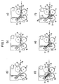
- Fig. 1a shows a folder for processing according to the invention a sheet of paper 10.
- a first folding roller 12 is vertically above a second folding roller 14 is arranged.
- Third folding roller 16 is arranged. All three folding rollers 12, 14 and 16 have the same peripheral speed on.
- the folding rollers 12 and 14 or 14 and 16 rotate opposite each other.
- Fig. 1a shows the time of sheet entry, too that of a conventional conveyor, for example a diagonal roller or bias belt table, conveyed sheet 10 den passes optical sensor 18 for detecting the sheet inlet.
- the sheet 10 is then from the Folding rollers 12 and 14 detected and with its front end in the folding pocket 20 promoted.
- Fig. 1c it can be seen that the two folding rollers 12 and 14 the folding sheet 10 up to the folding pocket stop 22 of the folding pocket Promote 20. Since the sheet 10 now has its front end on the fold pocket stop 22 is present, he can no longer go into the Move the fold pocket 20 in.
- the folding rollers 12, 14 and 16 continue to rotate so that a compression fold forms within the compression space 24, which then captured by the two counter-rotating folding rollers 14 and 16 becomes.
- Fig. 1e shows how the compression fold between the two folding rollers 14 and 16 is withdrawn.
- the time of the fold formation is shown in FIG. 1f.
- the folding rollers 14 and 16 practice one on the upset fold of the sheet 10 Force, which on the other hand also deflects the folding rollers 14 and 16 become.
- the folding roller 16 is at one end of a two-armed Lever 26 rotatably mounted, which can pivot about the bearing point 28.
- the lever 26 and thus the folding roller 16 are biased against the folding roller 14 by means of conventional adjusting and prestressing devices.
- a sensor 30 is arranged, which deflects the folding roller 16 detected.
- the sensor 30 accordingly becomes that shown in FIG. 1f
- a signal is sent to the evaluation unit 32 deliver.
- the optical sensor 18 for detecting the sheet entry is also connected to the evaluation unit 32.
- an incremental encoder 34 is provided which, depending from the rotation of the folding roller 16 pulses to the evaluation unit 32 delivers.
- the evaluation unit 32 has a counting device that counts the pulses emitted by the incremental encoder 34.
- the counting device the evaluation unit 32 is from the signal of the sensor 18, that this releases when passing the arch 10, triggered and by the signal of the sensor 30 that this at the time of the fold formation releases, stopped. In this way, the evaluation unit 32 the number of pulses counted between sheet entry and fold formation to disposal.
- the number of pulses can be determined by the evaluation unit 32 can also be converted into units of length of the conveyed sheet length.
- a display device is also provided in the evaluation unit 32, that with every folding process between sheet entry and fold formation conveyed arc length. This way there can be deviations from a target value, that of a correct fold formation corresponds to be determined immediately, without the position of the fold break must be measured on the finished folded sheet.
- FIG. 2 shows a second embodiment of the invention Pocket folding unit in a schematic representation.
- a bow 40 will be here also conveyed and folded by three folding rollers 42, 44 and 46.
- the optical sensor 48 not only detects the time of sheet entry but could also begin printing recognize on the sheet. He gives both when going through the At the beginning of the print sheet 40 as well as a signal when that Print image of the sheet 40 passes under the sensor 48.
- the folded sheet 40 is already completely in the folding pocket 50 has been conveyed and lies on the folding pocket stop 52 on.
- the Folding roller 46 is rotatably mounted on a two-armed lever 56, the can pivot about a bearing point 58 and biased against the folding roller 44 is.
- the deflection of the folding roller 46 when folding is formed detected by a sensor 60, which sends this signal to a control unit 62 delivers.
- the sensor 60 can both above and below the Bearing point 58 may be arranged.
- the position indicated by dashed lines of the sensor 60 is below the bearing point 58, in particular at Use of a strain gauge arrangement, particularly advantageous.
- the Folding roller 46 is provided with a gear 64 which is magnetic opposite inductive sensor 66.
- the magnetic inductive sensor 66 When the folding roller 46 rotates the magnetic inductive sensor 66 therefore provides pulses, each correspond to an incremental rotation of the folding roller 46. All three Folding rollers 42, 44 and 46 have the same peripheral speed, so that the conveyed sheet length at any of the folding rollers 42, 44th or 46 can be measured.
- the magnetic inductive sensor 66 is also electrically connected to the control unit 62. As input signals are in the control unit 62, as can be seen in FIG. 2, consequently the signals from sensor 48 at sheet entry and start of print image, the signal of the sensor 60 when the fold is formed and the incremental one Signal of the magnetic inductive sensor 66 available.
- the Control unit 62 controls a servomotor 68 which stops the folding pocket 52 moves.
- Fig. 2 shows an operating state of the folder in which the sheet speed is low. In this Operating state is a setpoint of the conveyed sheet length between Sheet run-in or print start and fold formation determined. This Learning phase is lower before the actual start of production Speed performed.
- Fig. 3 shows the folder of Fig. 2 at a higher sheet speed.
- the compression fold will therefore be on the sheet 40 at another Form position, which causes a positional deviation of the fold break gives the bow.
- the signal of the sensor 60 is only at a larger conveyed arc length, based on the signal from the sensor 48, take place.
- the control unit 62 therefore becomes a larger number of pulses detected by sensor 66 before the signal from sensor 60 upon formation of folds he follows. A deviation can therefore occur in the control unit 62 from the target value determined in the learning phase of FIG. 2 become.
- the control unit 62 therefore controls the servomotor 68 on, so that this the folding pocket stop 52 in the direction of Stowage space 54 shifts. The sheet length that can be inserted into the folding pocket is reduced so that the fold break of the next Sheet 40 are again in the correct position on the sheet becomes.
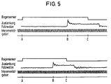
- FIG. 4 is the timing of the sensor signals Sensors 48, 60 and 66 of Figures 2 and 3 are shown schematically. in the 4 are the sensor signals at low speed, i.e. the state of FIG. 2 shown.
- the sheet / print image sensor 48 detects the sheet entry.
- the incremental encoder 66 is also from the sheet / print image sensor 48, the beginning of the printed image is recorded on the sheet. Thereby a correction value Lr is determined which, when regulated to the Print start of a sheet is required.
- time B the fold formation determined by the signal from sensor 60 which detects the deflection of the folding roller.
- the lower diagram in FIG. 4 corresponds to the timing of the sensor signals in the state shown in FIG. 3 with higher speed.
- the sheet / print image sensor in turn 48 the sheet entry and two pulses of Incremental encoder 66 later is the beginning of the print image on the sheet detected. This corresponds to the correction value Lr.
- the sheet deforms in the folding pocket as in the Fig. 3 is shown wave-like, so that a greater arc length in the Fold pocket is promoted before the wrinkle can form.
- the Time B at which sensor 60 detects the formation of folds takes place therefore later, so that between sheet inlet A and fold formation B a Arc length Ls + ⁇ L is promoted. In the one shown in FIG For example, ⁇ L is two pulses.
- control unit 62 To these additionally funded To compensate arc length ⁇ L, the control unit 62 must therefore Actuate the servomotor 68 so that it engages the folding pocket stop 52 moves until the between sheet inlet A and fold formation B determined number of pulses again corresponds to the setpoint Ls.
- FIG. 5 shows measurement records which show the sensor signals of the folding unit shown in FIG. 1. In the diagram above the ratios at low speed are shown. At time A, the sheet sensor 18 detects the sheet entry. At the time B is the deflection of the folding roller 16 at the sensor 30 Creasing found. Time C, is also marked which the sheet 10 has completely passed the sensor 18. The impulses are supplied by the incremental encoder 34.
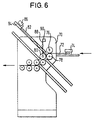
- FIG. 6 finally shows a schematic illustration of a folding machine 70 with a folding unit according to the invention.
- a sheet 72 runs under a sensor 74 for detecting the sheet entry and the beginning of the print image through and is detected by folding rollers 76, 78 and 80 and folded.
- a folding pocket stop 84 arranged, which is acted upon by a servomotor 86.
- the folding roller is the same as in the previously shown embodiments 80 rotatably mounted on a two-armed lever 88, on which the folding roller 80 opposite end, a sensor 90 for detecting the deflection the folding roller 80 is arranged when folding.
- On the follow first folding unit defined by folding rollers 76, 78 and 80 further folding units.
- the folding roller 80 of the first folding unit is used at the same time as the first folding roller of a second folding unit.
- the clarity half is in the folding machine 70 of FIG. 6 only one Folding unit according to the invention shown, of course, can however, all folding units of the type provided in the folding machine 70 folding unit according to the invention.
Landscapes
- Folding Of Thin Sheet-Like Materials, Special Discharging Devices, And Others (AREA)
Applications Claiming Priority (2)
| Application Number | Priority Date | Filing Date | Title |
|---|---|---|---|
| DE19747997A DE19747997A1 (de) | 1997-10-30 | 1997-10-30 | Taschenfalzwerk und Verfahren zur Registerregelung eines Taschenfalzwerks |
| DE19747997 | 1997-10-30 |
Publications (3)
| Publication Number | Publication Date |
|---|---|
| EP0913352A2 true EP0913352A2 (fr) | 1999-05-06 |
| EP0913352A3 EP0913352A3 (fr) | 1999-11-17 |
| EP0913352B1 EP0913352B1 (fr) | 2005-07-20 |
Family
ID=7847135
Family Applications (1)
| Application Number | Title | Priority Date | Filing Date |
|---|---|---|---|
| EP98119757A Expired - Lifetime EP0913352B1 (fr) | 1997-10-30 | 1998-10-22 | Plieuse à poches et procédé de contrôle du registre dans une plieuse à poches |
Country Status (5)
| Country | Link |
|---|---|
| US (1) | US6086522A (fr) |
| EP (1) | EP0913352B1 (fr) |
| JP (1) | JP4112709B2 (fr) |
| DE (2) | DE19747997A1 (fr) |
| PT (1) | PT913352E (fr) |
Cited By (1)
| Publication number | Priority date | Publication date | Assignee | Title |
|---|---|---|---|---|
| EP1013589A2 (fr) * | 1998-12-23 | 2000-06-28 | Heidelberger Druckmaschinen Aktiengesellschaft | Plieuse à poches et procédé de contrôle du registre dans une plieuse à poches |
Families Citing this family (25)
| Publication number | Priority date | Publication date | Assignee | Title |
|---|---|---|---|---|
| US6273313B1 (en) * | 1999-06-02 | 2001-08-14 | The Proctor & Gamble Company | Process and apparatus for controlling the registration of converting operations with prints on a web |
| US6689040B2 (en) | 1999-12-29 | 2004-02-10 | Pitney Bowes Inc. | Right angle turning device for an inserter system and corresponding method |
| DE10063528B4 (de) * | 2000-12-20 | 2011-05-19 | Goss International Montataire S.A. | Verfahren zur Bestimmung der Genauigkeit einer Falzlage |
| DE20218159U1 (de) * | 2002-11-22 | 2003-01-16 | Maschinenbau Oppenweiler Binder GmbH & Co. KG, 71570 Oppenweiler | Taschenfalzwerk für eine Falzmaschine |
| GB2397816B (en) * | 2002-12-20 | 2005-03-16 | Pfe Internat Ltd | Document folding apparatus |
| JP4189583B2 (ja) * | 2003-07-24 | 2008-12-03 | コニカミノルタビジネステクノロジーズ株式会社 | 用紙折り装置、用紙折り方法、後処理装置及び画像形成システム |
| ITTO20040826A1 (it) * | 2004-11-23 | 2005-02-23 | Petratto Srl | Macchina cordonatrice-piegatrice per la realizzazione di articoli cartotecnici e di legatoria |
| DE102004058647A1 (de) | 2004-12-06 | 2006-06-14 | Heidelberger Druckmaschinen Ag | Vorrichtung zum Falzen flacher Werkstücke |
| DE102005009132B4 (de) * | 2005-03-01 | 2019-03-14 | Manroland Goss Web Systems Gmbh | Verfahren zur Steuerung bzw. Regelung eines Falzapparats einer Druckmaschine |
| JP4514217B2 (ja) * | 2005-06-10 | 2010-07-28 | キヤノン株式会社 | シート処理装置および画像形成装置 |
| JP2007302383A (ja) * | 2006-05-10 | 2007-11-22 | Horizon International Inc | 紙折装置 |
| US7537556B2 (en) * | 2007-10-25 | 2009-05-26 | Xerox Corporation | High capacity knife folding system |
| DE102007054939A1 (de) * | 2007-11-17 | 2009-05-20 | Manroland Ag | Vorrichtung zum Falzen von Flachprodukten |
| DE102008007965B4 (de) * | 2008-02-07 | 2010-03-18 | Maschinenbau Oppenweiler Binder Gmbh & Co. Kg | Falztaschenvorrichtung |
| US8187158B2 (en) * | 2008-12-03 | 2012-05-29 | Petratto S.R.L. | Paper folding station |
| US9079744B2 (en) * | 2009-08-26 | 2015-07-14 | Horizon International Inc. | Sheet folding apparatus |
| WO2012072416A1 (fr) * | 2010-11-30 | 2012-06-07 | Oce-Technologies B.V. | Plieuse de feuilles, procédé de pliage de feuilles et système d'impression comprenant la plieuse de feuilles |
| DE102011010515A1 (de) * | 2011-02-07 | 2012-08-09 | Heidelberger Druckmaschinen Ag | Falzmaschine mit einer Einrichtung zum Falzkantenbeschnitt und Verfahren zum Falzen von Bogen |
| WO2012122324A1 (fr) | 2011-03-10 | 2012-09-13 | Ericson Manufacturing Company | Enveloppe de protection électrique |
| CH705358A1 (de) * | 2011-08-15 | 2013-02-15 | Ferag Ag | Vorrichtung und Verfahren zum Bearbeiten von Bogen aus Papier oder einem anderen flexiblen Material. |
| SE537530C2 (sv) * | 2013-04-26 | 2015-06-02 | Plockmatic Int Ab | Häftesframställningsmaskin med tjocklekssensor |
| US10792196B2 (en) * | 2014-01-23 | 2020-10-06 | Curt G. Joa, Inc. | Apparatus and method for high speed cross folding |
| CN103950781B (zh) * | 2014-04-21 | 2016-04-06 | 宁波荣华办公用品有限公司 | 叠图机的竖折机构 |
| US11872114B2 (en) | 2019-01-24 | 2024-01-16 | Curt G. Joa, Inc. | Method and apparatus for high-speed cross-folding of absorbent sanitary products |
| EP4389664A1 (fr) * | 2022-12-20 | 2024-06-26 | Heidelberger Druckmaschinen AG | Plieuse de feuilles avec évacuation de feuilles de rebut |
Citations (3)
| Publication number | Priority date | Publication date | Assignee | Title |
|---|---|---|---|---|
| DE9006855U1 (de) * | 1990-06-19 | 1990-08-30 | Bernd Diehm Ingenieurbüro für elektronische Steuerungen GmbH, 8902 Neusäß | Vorrichtung zur Bestimmung der Lage des Falzes bei einem Bogen |
| EP0725029A1 (fr) * | 1995-01-31 | 1996-08-07 | Neopost Industrie | Dispositif d'assistance au réglage de dimensions de pliage dans une machine plieuse inséreuse |
| EP0732293A2 (fr) * | 1995-03-15 | 1996-09-18 | STAHL GmbH & Co. Maschinenfabrik | Procédé pour optimiser le rendement d'exploitation d'une machine de pliage |
Family Cites Families (8)
| Publication number | Priority date | Publication date | Assignee | Title |
|---|---|---|---|---|
| DE2738689C3 (de) * | 1977-08-27 | 1981-05-21 | Mathias Bäuerle GmbH, 7742 ST. Georgen | Stauchfalzmaschine mit Falztaschen |
| US4701155A (en) * | 1986-07-11 | 1987-10-20 | R. Funk & Co., Inc. | Buckle chute folder with clamp |
| CA1308456C (fr) * | 1988-04-08 | 1992-10-06 | Jose Antonio Martinez Sanz | Capteur pour machine a plier et inserer du papier en feuille |
| DE4012859C2 (de) * | 1990-04-23 | 1993-12-16 | Baeuerle Gmbh Mathias | Stauchfalzmaschine mit Beilagenzuführeinrichtung |
| EP0511488A1 (fr) * | 1991-03-26 | 1992-11-04 | Mathias Bäuerle GmbH | Plieuse de papier avec des rouleaux plieurs réglables |
| DE4114105C2 (de) * | 1991-04-30 | 1994-09-15 | Baeuerle Gmbh Mathias | Stauchfalzmaschine |
| DE19515749C2 (de) * | 1995-04-28 | 1999-05-06 | Binder & Co Masch Oppenweiler | Verfahren zum Steuern der Bewegung eines einer Fensterfalztasche eines Taschenfalzwerkes zugeordneten Umlenkelementes |
| DE29516265U1 (de) * | 1995-10-13 | 1995-12-07 | Mathias Bäuerle GmbH, 78112 St Georgen | Stauchfalzmaschine mit einer Sammelfalztasche |
-
1997
- 1997-10-30 DE DE19747997A patent/DE19747997A1/de not_active Ceased
-
1998
- 1998-10-22 PT PT98119757T patent/PT913352E/pt unknown
- 1998-10-22 EP EP98119757A patent/EP0913352B1/fr not_active Expired - Lifetime
- 1998-10-22 DE DE59812937T patent/DE59812937D1/de not_active Expired - Lifetime
- 1998-10-29 US US09/182,255 patent/US6086522A/en not_active Expired - Lifetime
- 1998-10-30 JP JP31078198A patent/JP4112709B2/ja not_active Expired - Fee Related
Patent Citations (3)
| Publication number | Priority date | Publication date | Assignee | Title |
|---|---|---|---|---|
| DE9006855U1 (de) * | 1990-06-19 | 1990-08-30 | Bernd Diehm Ingenieurbüro für elektronische Steuerungen GmbH, 8902 Neusäß | Vorrichtung zur Bestimmung der Lage des Falzes bei einem Bogen |
| EP0725029A1 (fr) * | 1995-01-31 | 1996-08-07 | Neopost Industrie | Dispositif d'assistance au réglage de dimensions de pliage dans une machine plieuse inséreuse |
| EP0732293A2 (fr) * | 1995-03-15 | 1996-09-18 | STAHL GmbH & Co. Maschinenfabrik | Procédé pour optimiser le rendement d'exploitation d'une machine de pliage |
Cited By (3)
| Publication number | Priority date | Publication date | Assignee | Title |
|---|---|---|---|---|
| EP1013589A2 (fr) * | 1998-12-23 | 2000-06-28 | Heidelberger Druckmaschinen Aktiengesellschaft | Plieuse à poches et procédé de contrôle du registre dans une plieuse à poches |
| EP1013589A3 (fr) * | 1998-12-23 | 2002-05-15 | Heidelberger Druckmaschinen Aktiengesellschaft | Plieuse à poches et procédé de contrôle du registre dans une plieuse à poches |
| US6641514B1 (en) | 1998-12-23 | 2003-11-04 | Heidelberger Druckmaschinen Ag | Buckle folding unit and method for controlling the register of a buckle folding unit |
Also Published As
| Publication number | Publication date |
|---|---|
| JP4112709B2 (ja) | 2008-07-02 |
| EP0913352B1 (fr) | 2005-07-20 |
| PT913352E (pt) | 2005-11-30 |
| EP0913352A3 (fr) | 1999-11-17 |
| US6086522A (en) | 2000-07-11 |
| DE19747997A1 (de) | 1999-05-12 |
| DE59812937D1 (de) | 2005-08-25 |
| JPH11217157A (ja) | 1999-08-10 |
Similar Documents
| Publication | Publication Date | Title |
|---|---|---|
| EP0913352B1 (fr) | Plieuse à poches et procédé de contrôle du registre dans une plieuse à poches | |
| EP1790601B2 (fr) | Contrôle de la tension d'une bande de matériau | |
| DE2642381C3 (de) | Einrichtung zum registerhaltigen Zuführen einer Bahn | |
| DE68910390T2 (de) | Anordnung und Verfahren zum Regeln einer Vorrichtung für das Versiegeln von Packungen. | |
| EP2411309B1 (fr) | Procédé pour faire fonctionner une plieuse longitudinale présentant une lame de pliage et une table de pliage et plieuse longitudinale | |
| EP0475095A1 (fr) | Dispositif d'alignement d'une bande continue par rapport à une deuxième bande | |
| DE69714558T2 (de) | Beutelherstellungsapparat mit automatisches Positionssystem von Anschlusselementen | |
| DE19918399A1 (de) | Beeinflussung des FAN-OUT in einem Nassoffset Rotationsdruck | |
| DE60010027T2 (de) | Verfahren und Vorrichtung zur Querausrichtung eines Blattes mit einem auf diesem zu übertragenden Bild | |
| EP1013589B1 (fr) | Plieuse à poches et procédé de contrôle du registre dans une plieuse à poches | |
| DE19936291B4 (de) | Bestimmung von Schnittlagen von Bahnsträngen in einer Rotationsdruckmaschine | |
| DE102008048659A1 (de) | Vorrichtung und Verfahren zum Ausrichten von Bögen | |
| DE69102861T2 (de) | Verfahren zum Drucken. | |
| DE4202363A1 (de) | Vorrichtung zum trennen einer auch aus mehreren teilbahnen bestehenden bahn in abschnitte | |
| DE2711744C2 (de) | Verfahren und Vorrichtung zum Regeln des passerhaltigen und formatlängengerechten Drucks von mit Druckmarken versehenen vorbedruckten Bahnen in Druckmaschinen | |
| EP0755356B1 (fr) | Procede et dispositif permettant de reunir et de traiter des bandes de papier | |
| DE102009012815A1 (de) | Messvorrichtung mit beweglicher Messeinrichtung in einer Druckmaschine | |
| DE60215825T2 (de) | Rill- und faltvorrichtung und verfahren | |
| EP2108511B1 (fr) | Réglage d'un registre de coupe | |
| DE10352621B4 (de) | Verfahren zur seitlichen Ausrichtung einer Bahn | |
| EP1457310A2 (fr) | Procédé et dispositif pour la fabrication d'enveloppes | |
| EP2487127A1 (fr) | Procédé de détermination d'une position inclinée d'un pli produit par le pliage longitudinal d'un produit par un appareil de pliage longitudinal ainsi qu'appareil de pliage longitudinal doté de moyens de détermination d'une telle position inclinée | |
| DE102008054019A1 (de) | Rollenrotationsdruckmaschine und Verfahren zum Einstellen des Schnittregisters davon | |
| DE10003107B4 (de) | Verfahren und Vorrichtung für einen Transport einer Bedruckstoffbahn zwischen Funktionseinheiten einer Rotationsdruckmaschine in besonderen Betriebssituationen | |
| EP4434927A1 (fr) | Procédé de surveillance d'un processus de pliage dans une plieuse à poches |
Legal Events
| Date | Code | Title | Description |
|---|---|---|---|
| PUAI | Public reference made under article 153(3) epc to a published international application that has entered the european phase |
Free format text: ORIGINAL CODE: 0009012 |
|
| AK | Designated contracting states |
Kind code of ref document: A2 Designated state(s): CH DE IT LI PT |
|
| AX | Request for extension of the european patent |
Free format text: AL;LT;LV;MK;RO;SI |
|
| PUAL | Search report despatched |
Free format text: ORIGINAL CODE: 0009013 |
|
| AK | Designated contracting states |
Kind code of ref document: A3 Designated state(s): AT BE CH CY DE DK ES FI FR GB GR IE IT LI LU MC NL PT SE |
|
| AX | Request for extension of the european patent |
Free format text: AL;LT;LV;MK;RO;SI |
|
| RAP1 | Party data changed (applicant data changed or rights of an application transferred) |
Owner name: HEIDELBERGER DRUCKMASCHINEN AKTIENGESELLSCHAFT |
|
| 17P | Request for examination filed |
Effective date: 20000502 |
|
| AKX | Designation fees paid |
Free format text: CH DE IT LI PT |
|
| GRAP | Despatch of communication of intention to grant a patent |
Free format text: ORIGINAL CODE: EPIDOSNIGR1 |
|
| GRAS | Grant fee paid |
Free format text: ORIGINAL CODE: EPIDOSNIGR3 |
|
| GRAA | (expected) grant |
Free format text: ORIGINAL CODE: 0009210 |
|
| AK | Designated contracting states |
Kind code of ref document: B1 Designated state(s): CH DE IT LI PT |
|
| REG | Reference to a national code |
Ref country code: CH Ref legal event code: EP |
|
| REF | Corresponds to: |
Ref document number: 59812937 Country of ref document: DE Date of ref document: 20050825 Kind code of ref document: P |
|
| PLBE | No opposition filed within time limit |
Free format text: ORIGINAL CODE: 0009261 |
|
| STAA | Information on the status of an ep patent application or granted ep patent |
Free format text: STATUS: NO OPPOSITION FILED WITHIN TIME LIMIT |
|
| 26N | No opposition filed |
Effective date: 20060421 |
|
| PGFP | Annual fee paid to national office [announced via postgrant information from national office to epo] |
Ref country code: IT Payment date: 20061031 Year of fee payment: 9 |
|
| PG25 | Lapsed in a contracting state [announced via postgrant information from national office to epo] |
Ref country code: IT Free format text: LAPSE BECAUSE OF NON-PAYMENT OF DUE FEES Effective date: 20071022 |
|
| PGFP | Annual fee paid to national office [announced via postgrant information from national office to epo] |
Ref country code: DE Payment date: 20141031 Year of fee payment: 17 Ref country code: CH Payment date: 20141022 Year of fee payment: 17 |
|
| PGFP | Annual fee paid to national office [announced via postgrant information from national office to epo] |
Ref country code: PT Payment date: 20140929 Year of fee payment: 17 |
|
| REG | Reference to a national code |
Ref country code: PT Ref legal event code: MM4A Free format text: LAPSE DUE TO NON-PAYMENT OF FEES Effective date: 20160422 |
|
| REG | Reference to a national code |
Ref country code: DE Ref legal event code: R119 Ref document number: 59812937 Country of ref document: DE |
|
| REG | Reference to a national code |
Ref country code: CH Ref legal event code: PL |
|
| PG25 | Lapsed in a contracting state [announced via postgrant information from national office to epo] |
Ref country code: DE Free format text: LAPSE BECAUSE OF NON-PAYMENT OF DUE FEES Effective date: 20160503 Ref country code: LI Free format text: LAPSE BECAUSE OF NON-PAYMENT OF DUE FEES Effective date: 20151031 Ref country code: CH Free format text: LAPSE BECAUSE OF NON-PAYMENT OF DUE FEES Effective date: 20151031 |
|
| PG25 | Lapsed in a contracting state [announced via postgrant information from national office to epo] |
Ref country code: PT Free format text: LAPSE BECAUSE OF NON-PAYMENT OF DUE FEES Effective date: 20160422 |