EP0911190B1 - Machine de démontage de pneumatiques - Google Patents
Machine de démontage de pneumatiques Download PDFInfo
- Publication number
- EP0911190B1 EP0911190B1 EP98203156A EP98203156A EP0911190B1 EP 0911190 B1 EP0911190 B1 EP 0911190B1 EP 98203156 A EP98203156 A EP 98203156A EP 98203156 A EP98203156 A EP 98203156A EP 0911190 B1 EP0911190 B1 EP 0911190B1
- Authority
- EP
- European Patent Office
- Prior art keywords
- tyre
- electric motor
- current
- electronic card
- motor
- Prior art date
- Legal status (The legal status is an assumption and is not a legal conclusion. Google has not performed a legal analysis and makes no representation as to the accuracy of the status listed.)
- Expired - Lifetime
Links
Images


Classifications
-
- B—PERFORMING OPERATIONS; TRANSPORTING
- B60—VEHICLES IN GENERAL
- B60C—VEHICLE TYRES; TYRE INFLATION; TYRE CHANGING; CONNECTING VALVES TO INFLATABLE ELASTIC BODIES IN GENERAL; DEVICES OR ARRANGEMENTS RELATED TO TYRES
- B60C25/00—Apparatus or tools adapted for mounting, removing or inspecting tyres
- B60C25/01—Apparatus or tools adapted for mounting, removing or inspecting tyres for removing tyres from or mounting tyres on wheels
- B60C25/05—Machines
- B60C25/132—Machines for removing and mounting tyres
Definitions
- This invention concerns machines for mounting and removing a tyre on and from a wheel rim, and in particular relates to the means for their operation.
- Known machines for tyre mounting and removal on and from a wheel rim comprise an outer sheet metal casing, on the top of which there is located a rotary platform provided with self-centering means for locking the wheel rim.
- a vertical structure which supports, and locks in the required position, a horizontal arm, of which that end overlying the rotary platform supports the slide seat of a vertical arm.
- a tool which acts against the tyre edge to urge it below the edge of the wheel rim or to extract it therefrom.
- Said rotary platform is driven by an electric motor positioned within the casing via a connection shaft, between which a speed step-down gear is interposed.
- the electric motor used for driving the machine can be of three-phase induction or single-phase induction type.
- the electricity supply voltage differs for different countries, for example in Italy the three-phase a.c. supply voltage is 380V and the single-phase supply is at 220V, whereas in the United States the electricity supply is single-phase a.c. at 110V.
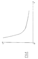
- a three-phase or single-phase induction motor is known to have a characteristic torque curve in which the torque varies substantially as the r.p.m. varies, within a very narrow range.
- DE 42 05 045 discloses a tyre fitting device comprising an electric motor (1) for relative rotation of the tyre and the vehicle wheel and a fitting tool, so that the tyre edge is fitted over the wheel rim while the latter is rotating.
- the rotary torque is controlled during the tyre fitting operation by controlling the current amplitude supplied to the electric motor (1), until a preset max. value is attained.
- the motor of said tyre fitting device is a three phase motor powered by three phase a.c.
- US 5,196,772 discloses an apparatus for fitting a motor vehicle tire on a disc wheel in which a fitting tool is driven to rotate about an axis by an electric drive motor.
- the said motor is preferably a three phase servomotor, although it is also possible to use a d.c. servomotor.
- a machine for mounting and removing tyres on and from a wheel rim there is a requirement for a machine for mounting and removing tyres on and from a wheel rim, the operation of which satisfies this torque requirement independently of the voltage and type of the power grid electricity.
- the object of the invention is to provide a machine for tyre mounting and removal on and from a wheel rim which overcomes the aforesaid drawbacks by virtue of the characteristics defined in the claims.
- Figure 1 is a section through the machine of the invention.
- Figure 2 is a schematic view of the drive motor for the machine of the invention.
- FIG. 3 shows the block diagram of the control and protection circuit for the machine of the invention.
- Figure 4 shows the characteristic torque/r.p.m. curve of the electric motor used by the invention.
- Said figures show the casing 1, from the top 2 of which there emerges the shaft 3 which rotatably supports the platform 4.
- Said circular platform 4 is provided with four usual radial slots, not shown, within which there move slides 5 upperly provided with jaws 6 for locking the wheel rim 7 in the working position.
- the slides 5 are driven by a usual pneumatic unit 8 supported within the lower part of the circular platform 4, as shown in Figure 1.
- a guide 12 of vertical axis which receives and can lock thereto a rod 13, to the lower end of which the tool 14 which acts against the tyre edge is connected.
- the circular platform 4 is rotated about its axis by the electric motor 15, means being interposed for reducing the rotational speed of the motor shaft.
- these means comprise a step-down gear 16 and the pair of pulleys 17 and 18 between which the belt 19 extends.
- the electric motor 15, shown schematically in Figure 2 is of series-excited single-phase type supplying a power output of between 350W and 600W with an absorbed current of between 10A and 15A.
- Such motors that can be used with a.c. and d.c. current are discussed in "series Alternating Current Motors - III" by J.L. Watts published in "Practical Engineering", 27 March 1953, pages 317-318.
- Said figure shows the stator 23 with its stator winding 24, the rotor 25 provided with brushes 26, and the terminal block 27 to which the ends of the stator and rotor circuits, 240, 241 and 260, 261 respectively, are connected.
- the leads 280, 281 from a speed indicator of tachometer type, and the leads 290, 291 from the motor thermal protection device, are also connected to the terminal block 27.
- an electronic card 20 for controlling and protecting the electric motor, and a reversing switch 21 operated by the start-stop pedal 22 of the tyre removal machine.
- Said electric motor 15 is powered with 220V a.c. in those regions in which this electrical voltage is available, or otherwise at 110V a.c.
- the electronic card 20 will comprise a rectifier stage to rectify the 110V a.c. supply to about 150V d.c. (rectified), to provide the power required for mounting and/or removing the tyre on or from the wheel rim.
- the electronic card 20 for powering the motor with a d.c. voltage of about 150V is shown in the block diagram of Figure 3.
- Said figure shows an initial stage 200 comprising components for filtering out the contaminating harmonics present in the mains a.c. supply and the protection devices at the input to the card 20.
- stage 201 Downstream of the stage 200 there is a stage 201 for measuring the current absorbed by the electric motor 15 and consisting for example of a usual ammeter-transformer which measures the current through the motor supply line and feeds the signal obtained to a measurement and control circuit represented by the block 202.
- the electric circuits represented by the block 202 which are not shown because they are of usual type, are powered by a power unit indicated by 203 in Figure 3.
- said block 202 comprises an input stage consisting of a rectifier and filter in which the a.c. signal from the ammeter-transformer is rectified, a comparator in which said rectified current signal is compared with a reference current value, generally the maximum current allowable through the motor to not exceed the desired torque, and set in the block 204, a memory circuit in which the measured value of said current signal is memorized, and a circuit for opening and closing the relay represented by the block 205.
- a block 207 comprising a motor filter and a block 208 consisting of a reversing switch which acts as a general switch and enables the direction of rotation of the rotor of the electric motor 15 to be reversed by acting on the contacts of the terminal block 27.
- the electric current absorbed by the line is proportional to the resistant torque applied to the shaft of the electric motor 15, which itself depends on the force applied to the tool 14 when it acts between the edge of the wheel rim and the edge of the tyre.
- the absorbed current must always be less than a value determined by the manufacturer of the electric motor 15 in order not to damage the rotor brushes 26.
- this determined value is 15A, and is preset in the block 204 to provide an operating limit.
- the control circuit for the relay 205 opens this latter to interrupt current feed to the electric motor 15.
- the described tyre removal machine can also be powered with 220V a.c. by replacing the electronic card 20 with an electronic card similar to that shown but without the rectifier stage 206.
Claims (2)
- Démonte-pneus comprenant une plate-forme pivotante (4) pour le soutien de la roue (7), les dispositifs (13 et 14) qui agissent sur le talon du pneumatique et les dispositifs (3 et 15-22) d'actionnement de la plate-forme; démonte-pneus caractérisé par le fait que les dispositifs d'actionnement (3 et 15-22) comprennent un moteur électrique monophasé à excitation en série (15) qui distribue une puissance comprise entre 350W et 600W, à absorption de courant non supérieure à 15A, dont les dispositifs de connexion (20) sont branchés à une ligne d'alimentation monophasée en courant alternatif; les dispositifs de connexion (20) sont constitués d'une carte électronique interchangeable (20) comprenant un redresseur de tension (108) fonctionnant en courant alternatif de 110V, pour redresser le courant alternatif à 110V, et de dispositifs (200-205) de limitation de l'absorption de courant à une valeur préétablie; la carte électronique (20) peut être remplacée par une carte électronique identique, sans redresseur de tension, qui permet au moteur électrique monophasé (15), au besoin, d'être raccordé à une ligne alimentée en 220V en courant alternatif.
- Démonte-pneus selon la revendication 1, caractérisé par le fait que la carte électronique comprend un mesureur de courant (201), un comparateur (202), un circuit de mémoire (202) et un circuit d'ouverture (202) pour un relais (205) fermé ensuite par relâchement de la pédale d'actionnement de la machine (22).
Applications Claiming Priority (2)
| Application Number | Priority Date | Filing Date | Title |
|---|---|---|---|
| ITRE970077 | 1997-10-24 | ||
| IT97RE000077A IT1297989B1 (it) | 1997-10-24 | 1997-10-24 | Macchina smontagomme |
Publications (2)
| Publication Number | Publication Date |
|---|---|
| EP0911190A1 EP0911190A1 (fr) | 1999-04-28 |
| EP0911190B1 true EP0911190B1 (fr) | 2002-11-27 |
Family
ID=11399117
Family Applications (1)
| Application Number | Title | Priority Date | Filing Date |
|---|---|---|---|
| EP98203156A Expired - Lifetime EP0911190B1 (fr) | 1997-10-24 | 1998-09-18 | Machine de démontage de pneumatiques |
Country Status (6)
| Country | Link |
|---|---|
| US (1) | US6227277B1 (fr) |
| EP (1) | EP0911190B1 (fr) |
| JP (1) | JP3749796B2 (fr) |
| AT (1) | ATE228441T1 (fr) |
| DE (1) | DE69809684T2 (fr) |
| IT (1) | IT1297989B1 (fr) |
Families Citing this family (11)
| Publication number | Priority date | Publication date | Assignee | Title |
|---|---|---|---|---|
| JP3626088B2 (ja) * | 2000-11-09 | 2005-03-02 | 小野谷機工株式会社 | 自動車タイヤ取外し方法、およびタイヤ取外し装置 |
| DE10116469B4 (de) * | 2001-04-03 | 2006-08-03 | Hofmann Maschinen- Und Anlagenbau Gmbh | Verfahren zum Aufziehen eines Kraftfahrzeugreifens auf eine Felge eines Scheibenrades |
| ITVR20020060A1 (it) * | 2002-05-29 | 2003-12-01 | Butler Eng & Marketing | Macchina monta-smontagomme |
| US7343955B2 (en) | 2005-12-28 | 2008-03-18 | Hennessy Industries, Inc. | Tire changing machine |
| US7438109B2 (en) * | 2005-12-30 | 2008-10-21 | Hennessy Industries, Inc. | Tire changer |
| US20100089257A1 (en) * | 2006-02-27 | 2010-04-15 | Entire Solutions Ltd | Apparatus for, and methods of, compacting a tyre part |
| US10513158B2 (en) | 2010-01-25 | 2019-12-24 | Snap-On Equipment Srl A Unico Socio | Method for mounting a tyre on a rim or demounting a tyre from a rim and apparatus therefore |
| EP2353889B1 (fr) * | 2010-01-25 | 2012-08-22 | Snap-on Equipment Srl a unico socio | Procédé d'assemblage d'un pneu sur une jante ou démontage de pneu d'une jante et appareil associé |
| PL3000627T3 (pl) * | 2014-09-23 | 2017-05-31 | Snap-On Equipment S.R.L. | Usprawniony sposób i urządzenie do montażu i demontażu opon z felg |
| IT201700065506A1 (it) | 2017-06-13 | 2018-12-13 | Snap On Equipment S R L A Unico Socio | Metodo ed apparato perfezionati per montare o smontare pneumatici su cerchioni |
| IT201900009321A1 (it) * | 2019-06-18 | 2020-12-18 | Nexion Spa | Apparato smontagomme |
Family Cites Families (11)
| Publication number | Priority date | Publication date | Assignee | Title |
|---|---|---|---|---|
| DE2621236C3 (de) * | 1976-05-13 | 1981-08-13 | Gebr. Hofmann Gmbh & Co Kg Maschinenfabrik, 6100 Darmstadt | Montage- und Demontagevorrichtung für Reifen |
| DE3513421A1 (de) * | 1985-04-15 | 1986-10-23 | Siemens AG, 1000 Berlin und 8000 München | Schaltungsanordnung zur strombegrenzung |
| US4840215A (en) * | 1987-02-02 | 1989-06-20 | Fmc Corporation | Tire changer safety post |
| US4809759A (en) * | 1987-02-02 | 1989-03-07 | Fmc Corporation | Tire changer safety arm |
| DE4028080C2 (de) * | 1990-09-05 | 2000-09-21 | Hofmann Maschinen Und Anlagenbau Gmbh | Vorrichtung zum Aufziehen von Kraftfahrzeugreifen auf Felgen von Scheibenrädern |
| DE4205045C1 (en) * | 1992-02-19 | 1993-08-19 | Hofmann Werkstatt-Technik Gmbh, 6102 Pfungstadt, De | Pneumatic tyre fitting device for vehicle wheel - uses current amplitude regulation of drive motor to control torque during fitting process |
| IT1262836B (it) * | 1993-09-09 | 1996-07-04 | Giuliano Vignoli | Macchina smontagomme ad azionamento pneumatico. |
| US5747955A (en) * | 1995-03-31 | 1998-05-05 | Quinton Instrument Company | Current sensing module for a variable speed AC motor drive for use with a treadmill |
| IT1287640B1 (it) * | 1996-05-03 | 1998-08-06 | Corghi Spa | Macchina per il montaggio e lo smontaggio dei pneumatici sui e dai rispettivi cerchioni |
| US5764463A (en) * | 1996-09-06 | 1998-06-09 | Hypro Corporation | Current limiting circuit and electronic fuse for use in foam injection fire fighting systems |
| US6137418A (en) * | 1998-03-05 | 2000-10-24 | Eaton Corporation | Single channel apparatus for on-line monitoring of three-phase AC motor stator electrical faults |
-
1997
- 1997-10-24 IT IT97RE000077A patent/IT1297989B1/it active IP Right Grant
-
1998
- 1998-09-18 EP EP98203156A patent/EP0911190B1/fr not_active Expired - Lifetime
- 1998-09-18 AT AT98203156T patent/ATE228441T1/de not_active IP Right Cessation
- 1998-09-18 DE DE69809684T patent/DE69809684T2/de not_active Expired - Fee Related
- 1998-09-21 US US09/157,579 patent/US6227277B1/en not_active Expired - Fee Related
- 1998-10-12 JP JP28917098A patent/JP3749796B2/ja not_active Expired - Fee Related
Also Published As
| Publication number | Publication date |
|---|---|
| EP0911190A1 (fr) | 1999-04-28 |
| ITRE970077A0 (it) | 1997-10-24 |
| JPH11301227A (ja) | 1999-11-02 |
| ITRE970077A1 (it) | 1999-04-24 |
| ATE228441T1 (de) | 2002-12-15 |
| DE69809684T2 (de) | 2003-04-10 |
| US6227277B1 (en) | 2001-05-08 |
| JP3749796B2 (ja) | 2006-03-01 |
| DE69809684D1 (de) | 2003-01-09 |
| IT1297989B1 (it) | 1999-12-20 |
Similar Documents
| Publication | Publication Date | Title |
|---|---|---|
| EP0911190B1 (fr) | Machine de démontage de pneumatiques | |
| US10666168B2 (en) | Electric tool | |
| CN109080381B (zh) | 用于将轮胎配装到轮辋及从其移除轮胎的改进方法和设备 | |
| US11511387B2 (en) | Electric tool | |
| CA1205165A (fr) | Marteau electromecanique | |
| CN109514405A (zh) | 电动作业机 | |
| CA2253917C (fr) | Procede et dispositif pour freiner un moteur tous courants | |
| EP3000627B1 (fr) | Procédé et dispositif améliorés pour monter ou démonter des pneumatiques sur des jantes | |
| EP2353889B1 (fr) | Procédé d'assemblage d'un pneu sur une jante ou démontage de pneu d'une jante et appareil associé | |
| US6659153B1 (en) | Device and method for putting motor vehicle tires onto rims of disk wheels | |
| US5196772A (en) | Apparatus for fitting tires on wheels | |
| JPH06327141A (ja) | かご形回転子を有する非同期機 | |
| US3906322A (en) | Shaft rotation responsive stopping means for a motor-driven chuck | |
| JP3667869B2 (ja) | 溶接機の電極輪の研磨方法 | |
| US6752016B2 (en) | Method and apparatus for balancing a motor vehicle wheel | |
| KR0129939Y1 (ko) | 휠 발란서의 모터 브레이크장치 | |
| JP3628624B2 (ja) | フライホイールの制動装置 | |
| JP2001508277A (ja) | 真空ポンプ用駆動装置 | |
| JPS62260570A (ja) | 電動機駆動制御装置 | |
| JPH05301152A (ja) | レンズ研削装置 |
Legal Events
| Date | Code | Title | Description |
|---|---|---|---|
| PUAI | Public reference made under article 153(3) epc to a published international application that has entered the european phase |
Free format text: ORIGINAL CODE: 0009012 |
|
| AK | Designated contracting states |
Kind code of ref document: A1 Designated state(s): AT BE CH CY DE DK ES FI FR GB GR IE IT LI LU MC NL PT SE |
|
| AX | Request for extension of the european patent |
Free format text: AL;LT;LV;MK;RO;SI |
|
| 17P | Request for examination filed |
Effective date: 19990913 |
|
| AKX | Designation fees paid |
Free format text: AT BE CH CY DE DK ES FI FR GB GR IE IT LI LU MC NL PT SE |
|
| 17Q | First examination report despatched |
Effective date: 20011016 |
|
| GRAG | Despatch of communication of intention to grant |
Free format text: ORIGINAL CODE: EPIDOS AGRA |
|
| GRAG | Despatch of communication of intention to grant |
Free format text: ORIGINAL CODE: EPIDOS AGRA |
|
| GRAH | Despatch of communication of intention to grant a patent |
Free format text: ORIGINAL CODE: EPIDOS IGRA |
|
| GRAH | Despatch of communication of intention to grant a patent |
Free format text: ORIGINAL CODE: EPIDOS IGRA |
|
| GRAA | (expected) grant |
Free format text: ORIGINAL CODE: 0009210 |
|
| AK | Designated contracting states |
Kind code of ref document: B1 Designated state(s): AT BE CH CY DE DK ES FI FR GB GR IE IT LI LU MC NL PT SE |
|
| PG25 | Lapsed in a contracting state [announced via postgrant information from national office to epo] |
Ref country code: NL Free format text: LAPSE BECAUSE OF FAILURE TO SUBMIT A TRANSLATION OF THE DESCRIPTION OR TO PAY THE FEE WITHIN THE PRESCRIBED TIME-LIMIT Effective date: 20021127 Ref country code: LI Free format text: LAPSE BECAUSE OF FAILURE TO SUBMIT A TRANSLATION OF THE DESCRIPTION OR TO PAY THE FEE WITHIN THE PRESCRIBED TIME-LIMIT Effective date: 20021127 Ref country code: GR Free format text: LAPSE BECAUSE OF FAILURE TO SUBMIT A TRANSLATION OF THE DESCRIPTION OR TO PAY THE FEE WITHIN THE PRESCRIBED TIME-LIMIT Effective date: 20021127 Ref country code: FR Free format text: LAPSE BECAUSE OF FAILURE TO SUBMIT A TRANSLATION OF THE DESCRIPTION OR TO PAY THE FEE WITHIN THE PRESCRIBED TIME-LIMIT Effective date: 20021127 Ref country code: FI Free format text: LAPSE BECAUSE OF FAILURE TO SUBMIT A TRANSLATION OF THE DESCRIPTION OR TO PAY THE FEE WITHIN THE PRESCRIBED TIME-LIMIT Effective date: 20021127 Ref country code: CH Free format text: LAPSE BECAUSE OF FAILURE TO SUBMIT A TRANSLATION OF THE DESCRIPTION OR TO PAY THE FEE WITHIN THE PRESCRIBED TIME-LIMIT Effective date: 20021127 Ref country code: BE Free format text: LAPSE BECAUSE OF FAILURE TO SUBMIT A TRANSLATION OF THE DESCRIPTION OR TO PAY THE FEE WITHIN THE PRESCRIBED TIME-LIMIT Effective date: 20021127 Ref country code: AT Free format text: LAPSE BECAUSE OF FAILURE TO SUBMIT A TRANSLATION OF THE DESCRIPTION OR TO PAY THE FEE WITHIN THE PRESCRIBED TIME-LIMIT Effective date: 20021127 |
|
| REF | Corresponds to: |
Ref document number: 228441 Country of ref document: AT Date of ref document: 20021215 Kind code of ref document: T |
|
| REG | Reference to a national code |
Ref country code: GB Ref legal event code: FG4D |
|
| REG | Reference to a national code |
Ref country code: CH Ref legal event code: EP |
|
| REG | Reference to a national code |
Ref country code: IE Ref legal event code: FG4D |
|
| REF | Corresponds to: |
Ref document number: 69809684 Country of ref document: DE Date of ref document: 20030109 |
|
| PG25 | Lapsed in a contracting state [announced via postgrant information from national office to epo] |
Ref country code: SE Free format text: LAPSE BECAUSE OF FAILURE TO SUBMIT A TRANSLATION OF THE DESCRIPTION OR TO PAY THE FEE WITHIN THE PRESCRIBED TIME-LIMIT Effective date: 20030227 Ref country code: PT Free format text: LAPSE BECAUSE OF FAILURE TO SUBMIT A TRANSLATION OF THE DESCRIPTION OR TO PAY THE FEE WITHIN THE PRESCRIBED TIME-LIMIT Effective date: 20030227 Ref country code: DK Free format text: LAPSE BECAUSE OF FAILURE TO SUBMIT A TRANSLATION OF THE DESCRIPTION OR TO PAY THE FEE WITHIN THE PRESCRIBED TIME-LIMIT Effective date: 20030227 |
|
| NLV1 | Nl: lapsed or annulled due to failure to fulfill the requirements of art. 29p and 29m of the patents act | ||
| PG25 | Lapsed in a contracting state [announced via postgrant information from national office to epo] |
Ref country code: ES Free format text: LAPSE BECAUSE OF FAILURE TO SUBMIT A TRANSLATION OF THE DESCRIPTION OR TO PAY THE FEE WITHIN THE PRESCRIBED TIME-LIMIT Effective date: 20030529 |
|
| REG | Reference to a national code |
Ref country code: CH Ref legal event code: PL |
|
| EN | Fr: translation not filed | ||
| PG25 | Lapsed in a contracting state [announced via postgrant information from national office to epo] |
Ref country code: LU Free format text: LAPSE BECAUSE OF NON-PAYMENT OF DUE FEES Effective date: 20030918 Ref country code: IE Free format text: LAPSE BECAUSE OF NON-PAYMENT OF DUE FEES Effective date: 20030918 Ref country code: GB Free format text: LAPSE BECAUSE OF NON-PAYMENT OF DUE FEES Effective date: 20030918 Ref country code: CY Free format text: LAPSE BECAUSE OF FAILURE TO SUBMIT A TRANSLATION OF THE DESCRIPTION OR TO PAY THE FEE WITHIN THE PRESCRIBED TIME-LIMIT Effective date: 20030918 |
|
| PG25 | Lapsed in a contracting state [announced via postgrant information from national office to epo] |
Ref country code: MC Free format text: LAPSE BECAUSE OF NON-PAYMENT OF DUE FEES Effective date: 20030930 |
|
| PLBE | No opposition filed within time limit |
Free format text: ORIGINAL CODE: 0009261 |
|
| STAA | Information on the status of an ep patent application or granted ep patent |
Free format text: STATUS: NO OPPOSITION FILED WITHIN TIME LIMIT |
|
| 26N | No opposition filed |
Effective date: 20030828 |
|
| GBPC | Gb: european patent ceased through non-payment of renewal fee |
Effective date: 20030918 |
|
| REG | Reference to a national code |
Ref country code: IE Ref legal event code: MM4A |
|
| PGFP | Annual fee paid to national office [announced via postgrant information from national office to epo] |
Ref country code: DE Payment date: 20070824 Year of fee payment: 10 |
|
| PGFP | Annual fee paid to national office [announced via postgrant information from national office to epo] |
Ref country code: IT Payment date: 20070727 Year of fee payment: 10 |
|
| PG25 | Lapsed in a contracting state [announced via postgrant information from national office to epo] |
Ref country code: IT Free format text: LAPSE BECAUSE OF NON-PAYMENT OF DUE FEES Effective date: 20080918 Ref country code: DE Free format text: LAPSE BECAUSE OF NON-PAYMENT OF DUE FEES Effective date: 20090401 |