EP0911104A1 - Vorrichtung zum Behandeln und Lageren von Kreismesser und Distanzringen - Google Patents
Vorrichtung zum Behandeln und Lageren von Kreismesser und Distanzringen Download PDFInfo
- Publication number
- EP0911104A1 EP0911104A1 EP98850149A EP98850149A EP0911104A1 EP 0911104 A1 EP0911104 A1 EP 0911104A1 EP 98850149 A EP98850149 A EP 98850149A EP 98850149 A EP98850149 A EP 98850149A EP 0911104 A1 EP0911104 A1 EP 0911104A1
- Authority
- EP
- European Patent Office
- Prior art keywords
- casing
- cutters
- spacers
- caracterized
- robot
- Prior art date
- Legal status (The legal status is an assumption and is not a legal conclusion. Google has not performed a legal analysis and makes no representation as to the accuracy of the status listed.)
- Withdrawn
Links
- 125000006850 spacer group Chemical group 0.000 title claims abstract description 44
- 238000003860 storage Methods 0.000 claims abstract description 21
- 238000005520 cutting process Methods 0.000 claims description 5
- 230000006835 compression Effects 0.000 claims description 4
- 238000007906 compression Methods 0.000 claims description 4
- 238000003032 molecular docking Methods 0.000 claims description 2
- 239000000463 material Substances 0.000 abstract description 9
- 230000000712 assembly Effects 0.000 abstract description 2
- 238000000429 assembly Methods 0.000 abstract description 2
- 229910000831 Steel Inorganic materials 0.000 abstract 1
- XAGFODPZIPBFFR-UHFFFAOYSA-N aluminium Chemical compound [Al] XAGFODPZIPBFFR-UHFFFAOYSA-N 0.000 abstract 1
- 229910052782 aluminium Inorganic materials 0.000 abstract 1
- 239000004411 aluminium Substances 0.000 abstract 1
- 239000010959 steel Substances 0.000 abstract 1
- 238000000034 method Methods 0.000 description 3
- 238000009434 installation Methods 0.000 description 2
- 238000004519 manufacturing process Methods 0.000 description 2
- 230000008859 change Effects 0.000 description 1
- 238000006073 displacement reaction Methods 0.000 description 1
- 230000007246 mechanism Effects 0.000 description 1
- 230000035515 penetration Effects 0.000 description 1
- 230000008569 process Effects 0.000 description 1
- 230000009467 reduction Effects 0.000 description 1
- 239000000725 suspension Substances 0.000 description 1
- 238000009966 trimming Methods 0.000 description 1
Images

Classifications
-
- B—PERFORMING OPERATIONS; TRANSPORTING
- B23—MACHINE TOOLS; METAL-WORKING NOT OTHERWISE PROVIDED FOR
- B23D—PLANING; SLOTTING; SHEARING; BROACHING; SAWING; FILING; SCRAPING; LIKE OPERATIONS FOR WORKING METAL BY REMOVING MATERIAL, NOT OTHERWISE PROVIDED FOR
- B23D35/00—Tools for shearing machines or shearing devices; Holders or chucks for shearing tools
- B23D35/008—Means for changing the cutting members
-
- Y—GENERAL TAGGING OF NEW TECHNOLOGICAL DEVELOPMENTS; GENERAL TAGGING OF CROSS-SECTIONAL TECHNOLOGIES SPANNING OVER SEVERAL SECTIONS OF THE IPC; TECHNICAL SUBJECTS COVERED BY FORMER USPC CROSS-REFERENCE ART COLLECTIONS [XRACs] AND DIGESTS
- Y10—TECHNICAL SUBJECTS COVERED BY FORMER USPC
- Y10S—TECHNICAL SUBJECTS COVERED BY FORMER USPC CROSS-REFERENCE ART COLLECTIONS [XRACs] AND DIGESTS
- Y10S483/00—Tool changing
- Y10S483/901—Robot end effectors
-
- Y—GENERAL TAGGING OF NEW TECHNOLOGICAL DEVELOPMENTS; GENERAL TAGGING OF CROSS-SECTIONAL TECHNOLOGIES SPANNING OVER SEVERAL SECTIONS OF THE IPC; TECHNICAL SUBJECTS COVERED BY FORMER USPC CROSS-REFERENCE ART COLLECTIONS [XRACs] AND DIGESTS
- Y10—TECHNICAL SUBJECTS COVERED BY FORMER USPC
- Y10T—TECHNICAL SUBJECTS COVERED BY FORMER US CLASSIFICATION
- Y10T483/00—Tool changing
- Y10T483/10—Process
-
- Y—GENERAL TAGGING OF NEW TECHNOLOGICAL DEVELOPMENTS; GENERAL TAGGING OF CROSS-SECTIONAL TECHNOLOGIES SPANNING OVER SEVERAL SECTIONS OF THE IPC; TECHNICAL SUBJECTS COVERED BY FORMER USPC CROSS-REFERENCE ART COLLECTIONS [XRACs] AND DIGESTS
- Y10—TECHNICAL SUBJECTS COVERED BY FORMER USPC
- Y10T—TECHNICAL SUBJECTS COVERED BY FORMER US CLASSIFICATION
- Y10T483/00—Tool changing
- Y10T483/15—Tool changing with means to condition or adjust tool or tool support
-
- Y—GENERAL TAGGING OF NEW TECHNOLOGICAL DEVELOPMENTS; GENERAL TAGGING OF CROSS-SECTIONAL TECHNOLOGIES SPANNING OVER SEVERAL SECTIONS OF THE IPC; TECHNICAL SUBJECTS COVERED BY FORMER USPC CROSS-REFERENCE ART COLLECTIONS [XRACs] AND DIGESTS
- Y10—TECHNICAL SUBJECTS COVERED BY FORMER USPC
- Y10T—TECHNICAL SUBJECTS COVERED BY FORMER US CLASSIFICATION
- Y10T483/00—Tool changing
- Y10T483/17—Tool changing including machine tool or component
- Y10T483/1733—Rotary spindle machine tool [e.g., milling machine, boring, machine, grinding machine, etc.]
- Y10T483/1736—Tool having specific mounting or work treating feature
-
- Y—GENERAL TAGGING OF NEW TECHNOLOGICAL DEVELOPMENTS; GENERAL TAGGING OF CROSS-SECTIONAL TECHNOLOGIES SPANNING OVER SEVERAL SECTIONS OF THE IPC; TECHNICAL SUBJECTS COVERED BY FORMER USPC CROSS-REFERENCE ART COLLECTIONS [XRACs] AND DIGESTS
- Y10—TECHNICAL SUBJECTS COVERED BY FORMER USPC
- Y10T—TECHNICAL SUBJECTS COVERED BY FORMER US CLASSIFICATION
- Y10T483/00—Tool changing
- Y10T483/18—Tool transfer to or from matrix
- Y10T483/1845—Plural matrices
-
- Y—GENERAL TAGGING OF NEW TECHNOLOGICAL DEVELOPMENTS; GENERAL TAGGING OF CROSS-SECTIONAL TECHNOLOGIES SPANNING OVER SEVERAL SECTIONS OF THE IPC; TECHNICAL SUBJECTS COVERED BY FORMER USPC CROSS-REFERENCE ART COLLECTIONS [XRACs] AND DIGESTS
- Y10—TECHNICAL SUBJECTS COVERED BY FORMER USPC
- Y10T—TECHNICAL SUBJECTS COVERED BY FORMER US CLASSIFICATION
- Y10T83/00—Cutting
- Y10T83/768—Rotatable disc tool pair or tool and carrier
- Y10T83/7747—With means to permit replacement of tool
Definitions
- the present invention relates primarily to a device to store and move cutters and spacers for the cutter assembly for a slitter mill for slitting or cutting coils of materials.
- the coils can be cut to a strip or strips of desired with.
- the cutter assembly can be used for trimming the edges of coils of material.
- the present invention relates to a rapid changing of the cutters and spacers of the cutting assembly, and the storage of the cutters and spacers.
- the lengthwise slitting of wide coils of material can preferably be performed be performed by a slitter, or cutter, or cutter assembly, or slitter mill which contains two annular cutters.
- the annular cutters can be positioned so that they are disposed substantially one above the other. Also the cutting surfaces of the cutters can at least partially overlap.
- the strip to be slit can be directed between two horizontal arbors, which two horizontal arbors can be substantially parallel to each other with one disposed substantially directly above the other.
- the arbors can be equipped with dish or disc shaped cutters and spacers.
- the spacers can be designed and positioned to separate the cutters so as to cut the strips or slits of material to desired with.
- the arbors can be supported by a frame.
- the frame can have two substantially vertical portions, which vertical portions can support the arbors.
- the vertical portions can also contain bearings to support the arbors.
- the vertical portions can also be supported by a common base plate.
- 0ne option requires the removal of the entire frame portion, along with the associated arbors and tool sets from the slitter machine. 0nce removed, the tool sets can be accessed for replacement of cutters and spacers. The frame and associated tool sets can then be replaced into the slitter machinery.
- Hnother option for the removal of the tool sets calls for the removal of just on of the frame portions. Upon removal of one of the frame portions, the tool sets can be removed, reassembled and reinstalled while the arbors remain in place, held by the other frame portion. The removed frame portion can then be reinstalled and the slitter can then once again be ready for operation.
- the latter method of replacement of the cutters and spacers is generally preferred, as it is commonly believed to be more time and cost efficient to replace the slitters in this manner.
- the patent EP 078 3942 describes a device to facilitate the removal and replacement of an entire tool set.
- Projections similar to the arbors on a slitter are disposed on an upright portion.
- the projections can be substantially parallel to one another. There can preferably be at least two such pairs of projections on the device, with each pair extending in a different direction.
- the device can be designed to move between a first position and a second position. In the first position the device stores the arbor sets. In the second, docked position, a pair of projections can dock with the arbors of the cutter. Upon docking, the used tool set can then be pushed onto the bars. The device can be rotated so another pair of bars, carrying the replacement tool set, can be docked with the arbors, and the new tool set can be transferred to the arbors.
- the device for removal and replacement and or/the slitter itself can be equipped with pushing mechanisms to push the old tool sets off of the arbors and the new tool sets onto the arbors.
- the cutters and spacers can be stored in an area near the slitting machine. Due to the number of cutters and spacers involved, and the number of combinations of cutters and spacers for all of the different materials and sizes of strips to be cut, an extensive storage area can be necessary. For example, it may be ne-cessary to have more than 100 different sizes of spacers aviable to set up the tool sets for the correct width of material to be cut. Also, each tool set can possibly include 30 or more cutters and spacers. Due to the number of components involved, an extensive amount of time can be required to correctly assemble all of the stored tool sets.
- a robot moving assembly is provided with a head that can be moved three-dimensionally within the storage area. Additionally, the robot head can have an axle, possibly a vertical axle, about which the robot head can rotate.
- the robot head can be equipped with a casing, which casing can contract in order to be put inside the tool sets and can expand in order to hold the tool sets so positioned.
- the present embodiment is at least one possible variant or embodiment of the present invention. Other embodiments are also possible.
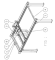
- a robot ,1, can include a stand ,2.
- the stand ,2, can have an extending portion which allows the robot ,1, to operate within substantially the entire storage area or region or space.
- the stand ,2, can include upright portions ,3, with each upright portion ,3, disposed to form a different corner of the storage area.
- the upright portions ,3, can be connected at the top by horizontal crossbars ,4, which horizontal crossbars ,4, can define the sides of the storage area.
- a carriage, or longitudinally running carriage ,5, can be movable horizontally on two of the crossbars ,4, which two crossbars ,4, can be substantially parallel to each other.
- the carriage ,5, can be operated by, for example a mo-tor ,6, which can be connected to the carriage ,5, by a cogged endless belt.
- the belt can be disposed to run substantially along, for example one of the crossbars ,4.
- a second or transverse carriage ,7 can be disposed to run substantially transverse to the longitudinal carriage ,5.
- the transverse carriage ,7 can also be operated by a motor through a treated shaft or screw.
- Mounted to the transverse carriage ,7 can be the bearer or lifter or mount ,8, which operates substantially vertically in the storage space.
- a robot head ,9 is mounted on the bearer ,8, at the bottom of the bearer ,8.
- the robot head ,9 can have a projecting gripping part or extension or appliance ,10.
- the head ,9 can rotate in a plane substantially transverse to the axis of the bearer ,8.
- stock units ,11 are mounted within the reach of the robot head ,9.
- Each stock unit ,11 has a vertical rectangular frame structure ,12. Projecting from one or both sides of the frame structure ,12, are projections or pipes or suspension attachments ,13.
- the outer diameter of the pipes ,13 is sized so that various cutters ,14, and spacers ,15, can be placed over various pipes ,13.
- the pipes are spaced a sufficient distance from another so that adjacent cutters ,14, and spacers ,15, will not contact each other when stored on the pipes ,13.
- Each pipe ,13 can also be equipped with a pusher or pushing device ,16, to push the cutters ,14, or spacers ,15, along the pipes ,13, away from the frame structures ,12.
- the gripping appliance or device ,10, of the robot head ,9 can be designed to grip the selected cutters ,14, and spacers ,15, from the storage area, and carry them to either a set-up area or directly to a slitter or cutter assembly for installation on the cutter or slitter.
- the gripping appliance 10 can also work in the reverse direction, carrying the selected cutters ,14, and spacers ,15, from the cutter assembly and to the storage area.
- the gripping appliance,10 has a casing ,17, with an outer surface ,18, which casing ,17, can expand to essentially match the inner diameter of the cutters ,14, and spacers ,15.
- the cutters ,14, and spacers ,15 When the casing ,17, is contracted, the cutters ,14, and spacers ,15, have sufficient radial clearance to easily move along the surface ,18, of the casing ,17.
- the casing ,17 can be slit into at least three distinct sections, can be slightly tapered so that the wall of the casing ,17, is thicker at the end nearest the robot head ,9, and thinner at the opposing end. Therefore the inside diameter of the casing ,17, can be smaller adjacent the robot head ,9, and larger at a distance from the robot head ,9.
- R mandrel ,19 is firmly connected to the robot head ,9, and is disposed inside the casing ,17.
- the surface of the mandrel ,19 can also be tapered to fit against the inner surface of the casing ,17.
- the casing ,17 can function as a collect for the holding of cutters ,14, and spacers ,15, on the casing ,17, as described be-ow.
- the three parts of the casing ,17, can be held together by springs ,20, which springs ,20, can be placed around the surface ,18, of the casing ,17.
- the casing ,17, can be designed so that the length of the casing ,17, corresponds to the maximum numbers of cutters ,14, and spacers ,15, that the gripping appliance ,10, is to carry at one time.
- the gripping appliance ,10 can be equipped with compression springs ,21, which compression springs ,21, push the casing ,17, along the mandrel ,19.
- the mandrel ,19 itself can be equipped with an outwardly projecting cone or conical section ,22.
- Each pipe ,13 can be equipped with a conical cavity ,23, which cavity ,23 is designed to receive the cone ,22, of the mandrel ,19.
- Each pipe ,13 can also have a cylindrical part or section ,24, which cylindrical section ,24, is disposed outside of the conical cavity ,23, to allow a greater penetration by the mandrel ,19, therefore forming a cylindrical opening adjacent the conical cavity ,23.
- the cutters ,14, and spacers ,15 can now freely slide along the outer envelope surface ,18, of the casing ,17.
- the cutters ,14 and spacers ,15 can be pushed onto the gripping apparatus ,10, by the pusher ,16.
- the compression spring ,21 pushes the casing ,17, along the mandrel ,19, and thus the diameter of the casing ,17, increases to the extent that the cutters ,14, and spacers ,15, are firmly held by frictional forces.
- An additional pusher or movable holder or retainer ,25 is movable along the envelope surface ,18, of the casing ,17.
- the robot ,1, and associated equipment are all controllable by a computer system to syncronize the movements of the various components.
- the pusher ,16, and the holder ,25 can also be controlled by the computer system.
- the computer can be directly connected to the slitter in order to store a task list based on the orders to be completed. In at least one embodiment, the whole slitter and storage operation can thus be computerized in order to optimize the production process.
- the tool sets to be assembled can be essentially assembled on the gripping appliance ,10.
- Rs the robot head ,9 is docked with the appropriate pipe ,13, the pusher ,16, for that particular pipe ,12, can push the selected number of cutters ,14, or spacers ,15, onto the casing ,17.
- the number of cutters ,14, or spacers ,15, transferred to the casing ,17 can depend primarily on the position of the holder ,25, on the gripping appliance ,10.
- the robot head ,9 After the robot head ,9, picks up the cutters ,14, and spacers ,15, to be transferred, the robot head ,9, can move adjacent either to a slitter or to a set-up area for the slitter.
- the cutters ,14, and spacers 15, can be removed from the casing ,17, by the holder ,25, which can act as a pusher for the removal of the tools from the casing ,17.
- the above process can be repeated in essentially the reverse order,
- the mandrel ,19 can contact the recess or cavity ,23, of the pipes ,13, thus causing the casing ,17, to decrease in diameter.
- the holder ,25 can act as a pusher to push the cutters ,14, or slitters ,15, onto the appropriate pipe ,13.
- the number of cutters ,14, and spacers ,15, to be transferred can be limited by the amount of displacement of the holder ,25.
- the total amount of storage space required can be reduced. Additionally, the total distance the robot head ,9, must move to assemble the tool sets can be reduced. The smaller storage area can also be stored closer to the cutter or slitter it is intended to service.
Landscapes
- Engineering & Computer Science (AREA)
- Mechanical Engineering (AREA)
- Shearing Machines (AREA)
- Details Of Cutting Devices (AREA)
- Manipulator (AREA)
Applications Claiming Priority (2)
| Application Number | Priority Date | Filing Date | Title |
|---|---|---|---|
| SE9703899 | 1997-10-27 | ||
| SE9703899A SE510789C2 (sv) | 1997-10-27 | 1997-10-27 | Anordning för hantering och lagring av skärstål och distansringar |
Publications (1)
| Publication Number | Publication Date |
|---|---|
| EP0911104A1 true EP0911104A1 (de) | 1999-04-28 |
Family
ID=20408744
Family Applications (1)
| Application Number | Title | Priority Date | Filing Date |
|---|---|---|---|
| EP98850149A Withdrawn EP0911104A1 (de) | 1997-10-27 | 1998-09-29 | Vorrichtung zum Behandeln und Lageren von Kreismesser und Distanzringen |
Country Status (5)
| Country | Link |
|---|---|
| US (1) | US6010441A (de) |
| EP (1) | EP0911104A1 (de) |
| KR (1) | KR19990036691A (de) |
| CA (1) | CA2248646A1 (de) |
| SE (1) | SE510789C2 (de) |
Cited By (11)
| Publication number | Priority date | Publication date | Assignee | Title |
|---|---|---|---|---|
| EP1074325A1 (de) * | 1999-08-06 | 2001-02-07 | CO Stahl und Technik GmbH | Verfahren und Vorrichtung zum Wechseln eines Werkzeugsatzes |
| DE10016795A1 (de) * | 2000-04-05 | 2001-10-18 | Norder Lagertechnik Gmbh | Vorrichtung zum Vorbau und zum Wechseln eines Werkzeugsatzes |
| EP1163977A2 (de) * | 2000-06-14 | 2001-12-19 | Norder Lagertechnik GmbH | Verfahren und Vorrichtung zum Reinigen von Werkzeugen für eine Spaltanlage |
| CN104118009A (zh) * | 2013-04-25 | 2014-10-29 | 好利用国际株式会社 | 冲裁机 |
| WO2014096948A3 (en) * | 2012-12-21 | 2014-10-30 | Make S.R.L. | System of improved type for loading and unloading cutting elements in order to assemble and disassemble sets of said cutting elements |
| CN107281505A (zh) * | 2017-07-31 | 2017-10-24 | 王昭 | 一种神经内科智能手术刀消毒保养设备 |
| CN108357051A (zh) * | 2017-01-26 | 2018-08-03 | 发那科株式会社 | 组装系统、组装方法以及组装单元 |
| CN108858492A (zh) * | 2018-06-21 | 2018-11-23 | 安徽昊森新材料科技有限公司 | 环保型塑木地板切割机 |
| CN110434464A (zh) * | 2019-08-26 | 2019-11-12 | 山东旺泰科技有限公司 | 换热原件的激光焊接方法及工装 |
| IT201900015875A1 (it) | 2019-09-09 | 2021-03-09 | Faspar S P A | Sistema automatizzato per comporre o scomporre formazioni di taglio |
| IT201900018809A1 (it) | 2019-10-15 | 2021-04-15 | Faspar S P A | Gruppo di supporto per utensili |
Families Citing this family (4)
| Publication number | Priority date | Publication date | Assignee | Title |
|---|---|---|---|---|
| EP1138413A3 (de) * | 2000-03-29 | 2002-09-11 | Murata Kikai Kabushiki Kaisha | Presse mit automatischer Werkzeugwechselfunktion und Werkzeugkassettewechselvorrichtung |
| DE10261995B4 (de) * | 2002-01-27 | 2005-11-24 | Kendro Laboratory Products Gmbh | Objekt-Lagervorrichtung |
| DE102005028358A1 (de) * | 2005-06-18 | 2006-12-21 | Alfing Keßler Sondermaschinen GmbH | Bearbeitungsmaschinenanordnung mit Roboter und Werkzeugmagazin |
| CN112276916A (zh) * | 2020-10-20 | 2021-01-29 | 攀枝花恒威化工有限责任公司 | 一种机器人码垛装置及其操作方法 |
Citations (3)
| Publication number | Priority date | Publication date | Assignee | Title |
|---|---|---|---|---|
| DE3333141A1 (de) * | 1983-09-14 | 1985-05-02 | Georg 5810 Witten Simon | Schnellspannvorrichtung |
| WO1990003242A1 (en) * | 1988-09-21 | 1990-04-05 | Akv I Kopparberg Ab | An improved cutter assembling means for slitters and the like |
| WO1996009145A1 (en) * | 1994-09-23 | 1996-03-28 | Asea Brown Boveri Ab | Robot installation |
Family Cites Families (10)
| Publication number | Priority date | Publication date | Assignee | Title |
|---|---|---|---|---|
| US3513743A (en) * | 1967-08-21 | 1970-05-26 | Nat Steel Corp | Multiple-head slitting apparatus |
| US3621527A (en) * | 1968-07-16 | 1971-11-23 | Martin H Michalak | Apparatus for making narrow sintered metal strips |
| US3800648A (en) * | 1972-08-10 | 1974-04-02 | Watanabe Kekkosho Kk | Apparatus for interchanging sheet-metal slitting equipments |
| US4183273A (en) * | 1978-04-10 | 1980-01-15 | Braner Enterprises, Inc. | Slitter having pivotal multiple spaced pairs of arbors |
| SE430682B (sv) * | 1982-05-06 | 1983-12-05 | Asea Ab | Sett och anordning att tillfora och bortfora detaljer vid en robotbetjenad bearbetningsmaskin |
| DE3818757A1 (de) * | 1988-05-31 | 1989-12-07 | Mannesmann Ag | Portal eines industrieroboters |
| SE8803349D0 (sv) * | 1988-09-21 | 1988-09-21 | Akv I Kopparberg Ab | Anordning vid skerverk |
| IT1235796B (it) * | 1989-09-11 | 1992-10-26 | Josb S P A | Macchina utensile a sostituzione automatica di "attuatori multifunzione" per eseguire automaticamente una sequenza di operazioni diverse, in particolare per l'installazione di organi di collegamento per l'assemblaggio di sottoinsiemi meccanici quali strutture aeronautiche, automobilistiche, nautiche ecc |
| JP3518883B2 (ja) * | 1993-10-19 | 2004-04-12 | 株式会社小松製作所 | パンチプレス機における金型管理方法 |
| SE510306C2 (sv) * | 1996-01-12 | 1999-05-10 | Akv Ortic Ab | Skärverk för band |
-
1997
- 1997-10-27 SE SE9703899A patent/SE510789C2/sv not_active IP Right Cessation
-
1998
- 1998-09-23 CA CA002248646A patent/CA2248646A1/en not_active Abandoned
- 1998-09-28 KR KR1019980040271A patent/KR19990036691A/ko not_active Application Discontinuation
- 1998-09-29 EP EP98850149A patent/EP0911104A1/de not_active Withdrawn
- 1998-10-01 US US09/164,679 patent/US6010441A/en not_active Expired - Fee Related
Patent Citations (3)
| Publication number | Priority date | Publication date | Assignee | Title |
|---|---|---|---|---|
| DE3333141A1 (de) * | 1983-09-14 | 1985-05-02 | Georg 5810 Witten Simon | Schnellspannvorrichtung |
| WO1990003242A1 (en) * | 1988-09-21 | 1990-04-05 | Akv I Kopparberg Ab | An improved cutter assembling means for slitters and the like |
| WO1996009145A1 (en) * | 1994-09-23 | 1996-03-28 | Asea Brown Boveri Ab | Robot installation |
Cited By (18)
| Publication number | Priority date | Publication date | Assignee | Title |
|---|---|---|---|---|
| EP1074325A1 (de) * | 1999-08-06 | 2001-02-07 | CO Stahl und Technik GmbH | Verfahren und Vorrichtung zum Wechseln eines Werkzeugsatzes |
| DE19937207C1 (de) * | 1999-08-06 | 2001-03-01 | Co Stahl Und Technik Gmbh | Verfahren und Vorrichtung zum automatischen Wechseln eines Werkzeugsatzes bei einer Längsteilanlage, insbesondere einer Spaltanlage |
| DE10016795A1 (de) * | 2000-04-05 | 2001-10-18 | Norder Lagertechnik Gmbh | Vorrichtung zum Vorbau und zum Wechseln eines Werkzeugsatzes |
| DE10016795C2 (de) * | 2000-04-05 | 2002-01-24 | Norder Lagertechnik Gmbh | Vorrichtung zum Vorbau und zum Wechseln eines Werkzeugsatzes |
| EP1163977A2 (de) * | 2000-06-14 | 2001-12-19 | Norder Lagertechnik GmbH | Verfahren und Vorrichtung zum Reinigen von Werkzeugen für eine Spaltanlage |
| EP1163977A3 (de) * | 2000-06-14 | 2003-09-10 | Norder Lagertechnik GmbH | Verfahren und Vorrichtung zum Reinigen von Werkzeugen für eine Spaltanlage |
| DE10029136B4 (de) * | 2000-06-14 | 2008-12-11 | Nlt Norder Lagertechnik Gmbh & Co. Maschinenbau Kg | Verfahren und Vorrichtung zum Reinigen von Werkzeugen für eine Spaltanlage |
| WO2014096948A3 (en) * | 2012-12-21 | 2014-10-30 | Make S.R.L. | System of improved type for loading and unloading cutting elements in order to assemble and disassemble sets of said cutting elements |
| CN104118009A (zh) * | 2013-04-25 | 2014-10-29 | 好利用国际株式会社 | 冲裁机 |
| CN104118009B (zh) * | 2013-04-25 | 2017-05-03 | 好利用国际株式会社 | 冲裁机 |
| CN108357051A (zh) * | 2017-01-26 | 2018-08-03 | 发那科株式会社 | 组装系统、组装方法以及组装单元 |
| CN108357051B (zh) * | 2017-01-26 | 2019-10-08 | 发那科株式会社 | 组装系统、组装方法以及组装单元 |
| US10532400B2 (en) | 2017-01-26 | 2020-01-14 | Fanuc Corporation | Assembly system, assembling method, and assembly unit |
| CN107281505A (zh) * | 2017-07-31 | 2017-10-24 | 王昭 | 一种神经内科智能手术刀消毒保养设备 |
| CN108858492A (zh) * | 2018-06-21 | 2018-11-23 | 安徽昊森新材料科技有限公司 | 环保型塑木地板切割机 |
| CN110434464A (zh) * | 2019-08-26 | 2019-11-12 | 山东旺泰科技有限公司 | 换热原件的激光焊接方法及工装 |
| IT201900015875A1 (it) | 2019-09-09 | 2021-03-09 | Faspar S P A | Sistema automatizzato per comporre o scomporre formazioni di taglio |
| IT201900018809A1 (it) | 2019-10-15 | 2021-04-15 | Faspar S P A | Gruppo di supporto per utensili |
Also Published As
| Publication number | Publication date |
|---|---|
| SE9703899L (sv) | 1999-04-28 |
| CA2248646A1 (en) | 1999-04-27 |
| SE510789C2 (sv) | 1999-06-21 |
| SE9703899D0 (sv) | 1997-10-27 |
| US6010441A (en) | 2000-01-04 |
| KR19990036691A (ko) | 1999-05-25 |
Similar Documents
| Publication | Publication Date | Title |
|---|---|---|
| EP0911104A1 (de) | Vorrichtung zum Behandeln und Lageren von Kreismesser und Distanzringen | |
| US11117233B2 (en) | Tool magazines of mechanical arrangements and methods for administering tools | |
| EP2982628A1 (de) | Automatisierte Vorrichtung zum Laden einer Bahnrolle | |
| JPH0441029A (ja) | 多数個取り小製品の仕分け集積装置 | |
| EP1552899B1 (de) | Schneidkantenwechselvorrichtung in einer schlitzmaschinenstation und schneidkantenwechselverfahren | |
| JPH08132149A (ja) | 順送り金型装置 | |
| JP3515952B2 (ja) | スリッタの刃物交換装置及び刃物交換方法 | |
| KR101061629B1 (ko) | 슬리터의 커터자동교체용 로보트핸드어셈블리 | |
| NL1020171C2 (nl) | Werkwijze en forceermachine voor het bewerken van een werkstuk. | |
| US4487356A (en) | Device having expandable mandrel for making nuclear fuel element storage tubes | |
| CN211841149U (zh) | 一种保持架支柱全自动成型机 | |
| US4648859A (en) | Apparatus for applying a sealing material to the edge of a length of packaging | |
| US6718853B2 (en) | Log saw apparatus and method | |
| KR101969826B1 (ko) | 노칭 가공기 | |
| CN111908224A (zh) | 自动上卷卸卷机构、分切机设备和分切机设备的使用方法 | |
| JP4597151B2 (ja) | スリッタースタンドの刃替装置および刃替方法 | |
| CN219971458U (zh) | 一种复合纱线缠绕机 | |
| KR101185066B1 (ko) | 슬리터의 커팅툴 자동 교체를 위한 더미 샤프트 장치 | |
| CN115385149B (zh) | 一种收卷设备及换卷方法 | |
| CN114918472B (zh) | 一种超高强度冷轧钢加工装置及其加工方法 | |
| NL1013906C2 (nl) | Forceermachine, werkwijze voor het forceren van een product en uitlaatsysteem of poelie omvattende een dergelijk product. | |
| CN215919299U (zh) | 一种带钢切割装置 | |
| CN214684503U (zh) | 可调节剪切宽度的铜合金带用分条机 | |
| CN218426303U (zh) | 一种激光切管机用辅助落料台 | |
| CN118616795A (zh) | 一种铝板材纵切装置 |
Legal Events
| Date | Code | Title | Description |
|---|---|---|---|
| PUAI | Public reference made under article 153(3) epc to a published international application that has entered the european phase |
Free format text: ORIGINAL CODE: 0009012 |
|
| AK | Designated contracting states |
Kind code of ref document: A1 Designated state(s): DE FI FR GB IT SE |
|
| AX | Request for extension of the european patent |
Free format text: AL;LT;LV;MK;RO;SI |
|
| 17P | Request for examination filed |
Effective date: 19991022 |
|
| AKX | Designation fees paid |
Free format text: DE FI FR GB IT SE |
|
| STAA | Information on the status of an ep patent application or granted ep patent |
Free format text: STATUS: THE APPLICATION IS DEEMED TO BE WITHDRAWN |
|
| 18D | Application deemed to be withdrawn |
Effective date: 20010403 |