EP0910271B1 - Universelles küchengerät - Google Patents
Universelles küchengerät Download PDFInfo
- Publication number
- EP0910271B1 EP0910271B1 EP97926979A EP97926979A EP0910271B1 EP 0910271 B1 EP0910271 B1 EP 0910271B1 EP 97926979 A EP97926979 A EP 97926979A EP 97926979 A EP97926979 A EP 97926979A EP 0910271 B1 EP0910271 B1 EP 0910271B1
- Authority
- EP
- European Patent Office
- Prior art keywords
- tool
- shaft
- shaft tube
- kitchen appliance
- basin
- Prior art date
- Legal status (The legal status is an assumption and is not a legal conclusion. Google has not performed a legal analysis and makes no representation as to the accuracy of the status listed.)
- Expired - Lifetime
Links
- 238000012545 processing Methods 0.000 claims description 12
- 238000003754 machining Methods 0.000 description 4
- 238000003825 pressing Methods 0.000 description 2
- 241000894006 Bacteria Species 0.000 description 1
- 238000013459 approach Methods 0.000 description 1
- 238000011161 development Methods 0.000 description 1
- 230000018109 developmental process Effects 0.000 description 1
- 239000000839 emulsion Substances 0.000 description 1
- 238000003780 insertion Methods 0.000 description 1
- 230000037431 insertion Effects 0.000 description 1
- 238000004898 kneading Methods 0.000 description 1
- 238000004519 manufacturing process Methods 0.000 description 1
- 238000002156 mixing Methods 0.000 description 1
- 238000012986 modification Methods 0.000 description 1
- 230000004048 modification Effects 0.000 description 1
- 238000003756 stirring Methods 0.000 description 1
- 238000012549 training Methods 0.000 description 1
Images

Classifications
-
- A—HUMAN NECESSITIES
- A47—FURNITURE; DOMESTIC ARTICLES OR APPLIANCES; COFFEE MILLS; SPICE MILLS; SUCTION CLEANERS IN GENERAL
- A47J—KITCHEN EQUIPMENT; COFFEE MILLS; SPICE MILLS; APPARATUS FOR MAKING BEVERAGES
- A47J43/00—Implements for preparing or holding food, not provided for in other groups of this subclass
- A47J43/25—Devices for grating
- A47J43/255—Devices for grating with grating discs or drums
-
- A—HUMAN NECESSITIES
- A47—FURNITURE; DOMESTIC ARTICLES OR APPLIANCES; COFFEE MILLS; SPICE MILLS; SUCTION CLEANERS IN GENERAL
- A47J—KITCHEN EQUIPMENT; COFFEE MILLS; SPICE MILLS; APPARATUS FOR MAKING BEVERAGES
- A47J19/00—Household machines for straining foodstuffs; Household implements for mashing or straining foodstuffs
- A47J19/04—Household implements for mashing potatoes or other foodstuffs
-
- A—HUMAN NECESSITIES
- A47—FURNITURE; DOMESTIC ARTICLES OR APPLIANCES; COFFEE MILLS; SPICE MILLS; SUCTION CLEANERS IN GENERAL
- A47J—KITCHEN EQUIPMENT; COFFEE MILLS; SPICE MILLS; APPARATUS FOR MAKING BEVERAGES
- A47J43/00—Implements for preparing or holding food, not provided for in other groups of this subclass
- A47J43/04—Machines for domestic use not covered elsewhere, e.g. for grinding, mixing, stirring, kneading, emulsifying, whipping or beating foodstuffs, e.g. power-driven
Definitions
- the invention relates to a kitchen appliance for editing and Processing food with a tubular, lockable and horizontally arranged boiler an outlet opening is provided in the front end wall thereof is, with a first of a drive motor driven tool, which on a in Longitudinal direction of the working boiler and in attached to a shaft tube rotating shaft and by means of a shaft tube Feed unit over the length of the boiler is movable.
- a kitchen appliance with the aforementioned features is in the WO 92/19 139; the universal kitchen device should thereby for processing and processing of food by chopping, mixing, stirring, kneading, pressing or the like or for the production of emulsions Be suitable for food, for which purpose different Tools, for example knives or wing mixers each interchangeable on the shaft that can be moved through the boiler are struck.
- Tools for example knives or wing mixers each interchangeable on the shaft that can be moved through the boiler are struck.
- the Press plate for emptying the boiler without rotation only moved along the work bowl via the feed unit becomes.
- the invention is therefore based on the object Kitchen appliance of the type mentioned above to train that processing and processing of food or emptying the boiler without one Tool changes are possible.
- the basic idea of the invention provides that in the Working boiler a second, disc-shaped and in its outer diameter the inner diameter of the Appropriate tool using the boiler the feed unit over the length of the boiler is arranged movably and the first tool in the longitudinal direction of the boiler relative to second tool movable and in one assigned recess of the second tool is retractable and that the second tool too its movement along the length of the work kettle on the acted upon by the feed unit and to Feed of the first tool sliding through the second tool-guided shaft tube can be coupled.
- the invention has the advantage that for Processing and processing of the food at the in Rotation offset shaft fastened first tool the food in the boiler can be moved through, the second tool being his Maintains rest position; after the corresponding connection and Machining process is the shaft with the one sitting on it Tool including the corrugated tube comprising it withdrawn until the tool is in the intended position Recess occurs in the second tool; without one
- the second tool can then be converted to the shaft tube be coupled so that when the Feed unit now the second tool in the longitudinal direction is movable through the boiler. That way an intervention from the outside into the boiler or in it working aggregates not required.
- the second tool as a disc-shaped press plate a ring seal arranged on the outer circumference is formed, according to an embodiment of the Invention the recess arranged in the second tool corresponds to the shape of the first tool.
- the Recess can also be designed so that several if necessary, replaceable tools in the recess are suitable for insertion.
- the first tool to be placed on the shaft as a Wing knife with two opposing wings formed and arranged in the second tool Recess corresponding to the shape of the first tool is designed.
- the invention provides a special embodiment continue to reduce the size of the kitchen appliance a modification of that from the generic WO 92/19139 already known feed unit for the shaft tube, insofar as this applies to the shaft tube Feed unit from one at a fixed and over one Motor drive rotatable spindle in the longitudinal direction of the Movable working boilers and the drive motor for the the first tool carrying a rotating shaft Sled exists.
- the drive motor on a parallel to the tubular Working boiler and at a radial distance from that Guide tube arranged and guided firmly with the one driven by the spindle movable shaft tube connected and connected to the shaft to drive them over a radial distance bridging toothed belt is coupled.
- the invention provides that work boilers, Drive motor and feed unit in one Housing are arranged.
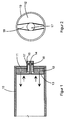
- 10 denotes a work boiler, on the rear end wall 11 a press plate 12 as the second Tool is in its rest position.
- the first tool which at the end of a Shaft 14 sits over a not shown Drive motor is rotatable; the shaft 14 is inside a corrugated tube 15 surrounding it arranged which shaft tube 15 through the rear End wall 11 and through the press plate 12 in one provided slide guide 17 is movable; for support the shaft 14 against the shaft tube 15 is a ball bearing 16.
- the second tool is 12 formed as a disc-shaped press plate that on its outer circumference carries an annular seal 19 and a Has recess 18, which in the illustrated Embodiment in its shape on a as Wing knife with two opposing wings trained first tool 13 is designed.
- the Recess 18 in the second tool 12 is so dimensioned that the first tool 13 completely in the Recess 18 can occur, after which on the second Tool 12 has a smooth end face that when feeding the second tool 12 through the Working boiler 10 ensures its emptying.
- FIGS. 3 and 4 further individual parts for its drive. So is hanging under the boiler 10 and parallel to its longitudinal axis at a radial distance from the shaft tube 15 or the shaft 14 a guide rail 20 is arranged, on which a Drive motor 21 by means of a sliding guide 28 in Longitudinal direction of the boiler 10 slidably arranged is.
- the output disk 22 of the drive motor 21 is included assigned to the shaft 14 at its end Toothed belt pulley 23 via a not shown Toothed belt coupled so that the drive motor 21 Shaft 14 is set in rotation.
- the drive motor 21 is with the shaft tube 15 via a rigid connection 27 firmly connected.
- WO 92/19139 realized are parallel to that in the Starting position above the working boiler Shaft tube 15 spindles 26 arranged by one not Motor drive shown are set in rotation.
- the Shaft tube 15 carries at its end a base plate 24 which with a support on a rail 29 with lateral approaches 25 on the two spindles 26 such is that a rotation of the spindles 26 to a Longitudinal movement of the shaft tube 24 leads.
Landscapes
- Engineering & Computer Science (AREA)
- Food Science & Technology (AREA)
- Mechanical Engineering (AREA)
- Food-Manufacturing Devices (AREA)
- Filters For Electric Vacuum Cleaners (AREA)
- Combinations Of Kitchen Furniture (AREA)
- Harvester Elements (AREA)
- Centrifugal Separators (AREA)
Description
- Fig. 1
- Arbeitskessel und Werkzeug eines Küchengerätes in einer Seitenansicht im Schnitt,
- Fig. 2
- das zweite Werkzeug in einer Einzeldarstellung in Draufsicht,
- Fig. 3
- das Küchengerät mit Antrieb in einer schematischen, teilweise geschnittenen Seitenansicht,
- Fig. 4
- eine schematische Rückansicht auf die Antriebsseite des Küchengerätes.
Claims (6)
- Küchengerät zum Bearbeiten und Verarbeiten von Nahrungsmitteln mit einem röhrenförmigen, verschließbaren und liegend angeordneten Kessel (10), an dessen vorderer Stirnwand eine Auslaßöffnung vorgesehen ist, mit einem ersten (13) von einem Antriebsmotor angetriebenen Werkzeug, welches an einer in Längsrichtung des Arbeitskessels verlaufenden und in einem Wellenrohr (15) rotierend geführten Welle (14) befestigt und mittels einer das Wellenrohr aufschlagenden Vorschubeinheit über die Länge des Arbeitskessels (10) bewegbar ist, dadurch gekennzeichnet, daß in dem Arbeitskessel (10) ein zweites, scheibenförmiges und in seinem Außendurchmesser dem Innendurchmesser des Arbeitskessels (10) entsprechendes Werkzeug (12) mittels der Vorschubeinheit über die Länge des Arbeitskessels (10) bewegbar angeordnet ist und das erste Werkzeug (13) in Längsrichtung des Arbeitskessels (10) relativ zum zweiten Werkzeug (12) beweglich und in einer zugeordneten Ausnehmung (18) des zweiten Werkzeuges (12) versenkbar ist und daß das zweite Werkzeug (12) zu seiner Bewegung über die Länge des Arbeitskessels (10) an dem von der Vorschubeinheit beaufschlagten und zum Vorschub des ersten Werkzeuges (13) gleitend durch das zweite Werkzeug (12) geführten Wellenrohr (15) ankoppelbar ist.
- Küchengerät nach Anspruch 1, dadurch gekennzeichnet, daß das zweite Werkzeug (12) als scheibenförmige Preßplatte mit einer auf dem äußeren Umfang angeordneten Ringdichtung ausgebildet ist.
- Küchengerät nach Anspruch 1 oder 2, dadurch gekennzeichnet, daß die in dem zweiten Werkzeug (12) angeordnete Ausnehmung (18) der Form des ersten Werkzeuges (13) entspricht.
- Küchengerät nach Anspruch 3, dadurch gekennzeichnet, daß das auf die Welle (14) aufzusetzende erste Werkzeug (13) als ein Flügelmesser mit zwei einander gegenüberstehenden Flügeln ausgebildet und die in dem zweiten Werkzeug (12) angeordnete Ausnehmung (18) der Form des ersten Werkzeuges (13) entsprechend ausgestaltet ist.
- Küchengerät nach einem der Ansprüche 1 bis 4, wobei die das Wellenrohr beaufschlagende Vorschubeinheit aus einem an einer ortsfesten und über einen Motorantrieb drehbaren Spindel in Längsrichtung des Arbeitskessels verfahrbaren und den Antriebsmotor für die das erste Werkzeug in Rotation versetzende Welle tragenden Schlitten besteht, dadurch gekennzeichnet, daß der Antriebsmotor (21) an einer parallel zum röhrenförmigen Arbeitskessel (10) und mit radialem Abstand zu dem Wellenrohr (15) angeordneten Führungsschiene geführt und fest mit dem durch die angetriebene Spindel (26) bewegbaren Wellenrohr (15) verbunden und mit der Welle (14) zu deren Antrieb über einen den radialen Abstand überbrückenden Zahnriemen gekoppelt ist.
- Küchengerät nach einem der Ansprüche 1 bis 5, dadurch gekennzeichnet, daß Arbeitskessel (10), Antriebsmotor (21) und Vorschubeinheit in einem gemeinsamen Gehäuse angeordnet sind.
Applications Claiming Priority (3)
| Application Number | Priority Date | Filing Date | Title |
|---|---|---|---|
| DE19622979A DE19622979A1 (de) | 1996-06-08 | 1996-06-08 | Universelles Küchengerät |
| DE19622979 | 1996-06-08 | ||
| PCT/DE1997/001130 WO1997047225A1 (de) | 1996-06-08 | 1997-06-05 | Universelles küchengerät |
Publications (2)
| Publication Number | Publication Date |
|---|---|
| EP0910271A1 EP0910271A1 (de) | 1999-04-28 |
| EP0910271B1 true EP0910271B1 (de) | 2000-12-20 |
Family
ID=7796451
Family Applications (1)
| Application Number | Title | Priority Date | Filing Date |
|---|---|---|---|
| EP97926979A Expired - Lifetime EP0910271B1 (de) | 1996-06-08 | 1997-06-05 | Universelles küchengerät |
Country Status (6)
| Country | Link |
|---|---|
| EP (1) | EP0910271B1 (de) |
| AT (1) | ATE198131T1 (de) |
| AU (1) | AU3164297A (de) |
| DE (2) | DE19622979A1 (de) |
| ES (1) | ES2155689T3 (de) |
| WO (1) | WO1997047225A1 (de) |
Families Citing this family (1)
| Publication number | Priority date | Publication date | Assignee | Title |
|---|---|---|---|---|
| AT413698B (de) * | 2002-09-27 | 2006-05-15 | Suedzucker Ag | Mischvorrichtung und abdeckvorrichtung, verwendung derselben sowie verfahren zur modifizierung und derivatisierung von kohlenhydraten |
Family Cites Families (7)
| Publication number | Priority date | Publication date | Assignee | Title |
|---|---|---|---|---|
| DE1079597B (de) * | 1952-03-12 | 1960-04-14 | Peter Willems | Misch- und Dispergiervorrichtung |
| DE1181091B (de) * | 1959-07-31 | 1964-11-05 | Oatley Technical Developments | Wolf zum Zerkleinern von Fleisch und sonstigen Nahrungsmitteln |
| FR1584144A (de) * | 1968-08-13 | 1969-12-12 | ||
| DE2856608A1 (de) * | 1978-12-29 | 1980-07-10 | Geb Frech Maria Jakob | Kuechenmaschine |
| US5458417A (en) * | 1991-04-27 | 1995-10-17 | Thomas Grelich | Universal kitchen appliance |
| DE4215882A1 (de) * | 1992-05-14 | 1993-11-18 | Braun Ag | Küchenmaschine |
| DE9409356U1 (de) * | 1994-06-09 | 1994-10-06 | Schaack, Edgar, 63755 Alzenau | Vorrichtung zum Pressen, Zerdrücken und/oder Zerkleinern von Nahrungsmitteln |
-
1996
- 1996-06-08 DE DE19622979A patent/DE19622979A1/de not_active Withdrawn
-
1997
- 1997-06-05 WO PCT/DE1997/001130 patent/WO1997047225A1/de not_active Ceased
- 1997-06-05 EP EP97926979A patent/EP0910271B1/de not_active Expired - Lifetime
- 1997-06-05 AU AU31642/97A patent/AU3164297A/en not_active Abandoned
- 1997-06-05 ES ES97926979T patent/ES2155689T3/es not_active Expired - Lifetime
- 1997-06-05 AT AT97926979T patent/ATE198131T1/de not_active IP Right Cessation
- 1997-06-05 DE DE59702790T patent/DE59702790D1/de not_active Expired - Fee Related
Also Published As
| Publication number | Publication date |
|---|---|
| AU3164297A (en) | 1998-01-07 |
| DE59702790D1 (de) | 2001-01-25 |
| WO1997047225A1 (de) | 1997-12-18 |
| ES2155689T3 (es) | 2001-05-16 |
| DE19622979A1 (de) | 1997-12-11 |
| ATE198131T1 (de) | 2001-01-15 |
| EP0910271A1 (de) | 1999-04-28 |
Similar Documents
| Publication | Publication Date | Title |
|---|---|---|
| DE2602262B2 (de) | Vorrichtung für das Abkanten von topfförmigen, metallenen Werkstücken, insbesondere Dosenriimpfen u.dgl | |
| DE1427529B2 (de) | Vorrichtung zum Schleifen der Hauptschneiden und Freiflächen von Spiralbohrern | |
| DE3723133C1 (de) | Fraes-Werkzeug fuer eine numerisch gesteuerte Werkzeugmaschine zum Herstellen einer profilierten aufgeweiteten Bohrung | |
| DE2921665A1 (de) | Vorrichtung zum selbsttaetigen vorschub von schneidmessern an tabakschneidmaschinen | |
| EP0570677B1 (de) | Zerkleinerungs- und Mischeinrichtung für eine Vielzweckküchenmaschine | |
| DE2634224A1 (de) | Verfahren und vorrichtung zum herstellen von vollkoerpern aus zerspanbarem werkstoff | |
| EP0910271B1 (de) | Universelles küchengerät | |
| DE1913377A1 (de) | Drehautomat | |
| DE2108338B2 (de) | Schneidvorrichtung zum Unterteilen kontinuierlich angelieferter Material-Stränge | |
| DE1652220A1 (de) | Verfahren zum spanabhebenden Bearbeiten eines Werkstuecks zu einem zylindrischen Gegenstand und Werkzeugmaschine dafuer | |
| DE1427551C3 (de) | Spiralbohrerschleifmaschine | |
| DE591024C (de) | Maschine zum Fraesen spiralfoermiger Nuten in Steuernocken mittels Fingerfraesers | |
| DE946320C (de) | Fraeseinrichtung, insbesondere zum Fraesen von Schlitzen oder Nuten | |
| DE494489C (de) | Schleifvorrichtung fuer Sichelmesser bei Strangzigarettenmaschinen | |
| AT413087B (de) | Vorrichtung zum bearbeiten von holzstäben oder holzsäulen | |
| DE906278C (de) | Maschine zum Schneiden von schraubenfoermigen Rillen in zylindrische Flaechen | |
| DE807880C (de) | Kopierwerkzeugmaschine mit mehreren Fuehlfingern | |
| DE2409661A1 (de) | Bohrmaschine | |
| DE1119145B (de) | Maschine zum Zerkleinern, Mischen und Umruehren von Lebensmitteln, insbesondere Fleisch | |
| DE3306137A1 (de) | Antriebsspindel fuer eine maschine zum hinterdrehen und bzw. oder schaerfen von reib- und fraeswerkzeugen | |
| DE2732882C3 (de) | Einrichtung zur Reinigung des Innengewindes von Muttern | |
| DE1427529C (de) | Vorrichtung zum Schleifen der Haupt schneiden und Freiflächen von Spiralboh | |
| DE2548472A1 (de) | Rotormaschine zum beschneiden von hohlteilen | |
| DE1184069B (de) | Vorrichtung zum Schneiden von Schichten von elastischem Schneidgut | |
| DE221634C (de) |
Legal Events
| Date | Code | Title | Description |
|---|---|---|---|
| PUAI | Public reference made under article 153(3) epc to a published international application that has entered the european phase |
Free format text: ORIGINAL CODE: 0009012 |
|
| 17P | Request for examination filed |
Effective date: 19990107 |
|
| AK | Designated contracting states |
Kind code of ref document: A1 Designated state(s): AT CH DE ES FR GB IT LI |
|
| GRAG | Despatch of communication of intention to grant |
Free format text: ORIGINAL CODE: EPIDOS AGRA |
|
| 17Q | First examination report despatched |
Effective date: 19990531 |
|
| GRAG | Despatch of communication of intention to grant |
Free format text: ORIGINAL CODE: EPIDOS AGRA |
|
| GRAH | Despatch of communication of intention to grant a patent |
Free format text: ORIGINAL CODE: EPIDOS IGRA |
|
| GRAH | Despatch of communication of intention to grant a patent |
Free format text: ORIGINAL CODE: EPIDOS IGRA |
|
| GRAA | (expected) grant |
Free format text: ORIGINAL CODE: 0009210 |
|
| AK | Designated contracting states |
Kind code of ref document: B1 Designated state(s): AT CH DE ES FR GB IT LI |
|
| REF | Corresponds to: |
Ref document number: 198131 Country of ref document: AT Date of ref document: 20010115 Kind code of ref document: T |
|
| REG | Reference to a national code |
Ref country code: CH Ref legal event code: EP |
|
| REF | Corresponds to: |
Ref document number: 59702790 Country of ref document: DE Date of ref document: 20010125 |
|
| ITF | It: translation for a ep patent filed | ||
| ET | Fr: translation filed | ||
| GBT | Gb: translation of ep patent filed (gb section 77(6)(a)/1977) |
Effective date: 20010410 |
|
| REG | Reference to a national code |
Ref country code: CH Ref legal event code: NV Representative=s name: HANS RUDOLF GACHNANG PATENTANWALT |
|
| REG | Reference to a national code |
Ref country code: ES Ref legal event code: FG2A Ref document number: 2155689 Country of ref document: ES Kind code of ref document: T3 |
|
| PG25 | Lapsed in a contracting state [announced via postgrant information from national office to epo] |
Ref country code: GB Free format text: LAPSE BECAUSE OF NON-PAYMENT OF DUE FEES Effective date: 20010605 |
|
| PLBE | No opposition filed within time limit |
Free format text: ORIGINAL CODE: 0009261 |
|
| STAA | Information on the status of an ep patent application or granted ep patent |
Free format text: STATUS: NO OPPOSITION FILED WITHIN TIME LIMIT |
|
| 26N | No opposition filed | ||
| GBPC | Gb: european patent ceased through non-payment of renewal fee |
Effective date: 20010605 |
|
| PGFP | Annual fee paid to national office [announced via postgrant information from national office to epo] |
Ref country code: CH Payment date: 20031212 Year of fee payment: 7 |
|
| PGFP | Annual fee paid to national office [announced via postgrant information from national office to epo] |
Ref country code: FR Payment date: 20031216 Year of fee payment: 7 |
|
| PGFP | Annual fee paid to national office [announced via postgrant information from national office to epo] |
Ref country code: ES Payment date: 20031223 Year of fee payment: 7 |
|
| PGFP | Annual fee paid to national office [announced via postgrant information from national office to epo] |
Ref country code: AT Payment date: 20031229 Year of fee payment: 7 |
|
| PG25 | Lapsed in a contracting state [announced via postgrant information from national office to epo] |
Ref country code: AT Free format text: LAPSE BECAUSE OF NON-PAYMENT OF DUE FEES Effective date: 20040605 |
|
| PG25 | Lapsed in a contracting state [announced via postgrant information from national office to epo] |
Ref country code: ES Free format text: LAPSE BECAUSE OF NON-PAYMENT OF DUE FEES Effective date: 20040607 |
|
| PG25 | Lapsed in a contracting state [announced via postgrant information from national office to epo] |
Ref country code: LI Free format text: LAPSE BECAUSE OF NON-PAYMENT OF DUE FEES Effective date: 20040630 Ref country code: CH Free format text: LAPSE BECAUSE OF NON-PAYMENT OF DUE FEES Effective date: 20040630 |
|
| REG | Reference to a national code |
Ref country code: CH Ref legal event code: PL |
|
| PG25 | Lapsed in a contracting state [announced via postgrant information from national office to epo] |
Ref country code: FR Free format text: LAPSE BECAUSE OF NON-PAYMENT OF DUE FEES Effective date: 20050228 |
|
| REG | Reference to a national code |
Ref country code: FR Ref legal event code: ST |
|
| PG25 | Lapsed in a contracting state [announced via postgrant information from national office to epo] |
Ref country code: IT Free format text: LAPSE BECAUSE OF NON-PAYMENT OF DUE FEES Effective date: 20050605 |
|
| PGFP | Annual fee paid to national office [announced via postgrant information from national office to epo] |
Ref country code: DE Payment date: 20060331 Year of fee payment: 10 |
|
| REG | Reference to a national code |
Ref country code: ES Ref legal event code: FD2A Effective date: 20040607 |
|
| PG25 | Lapsed in a contracting state [announced via postgrant information from national office to epo] |
Ref country code: DE Free format text: LAPSE BECAUSE OF NON-PAYMENT OF DUE FEES Effective date: 20080101 |