EP0909922B1 - Système de commande combinée à gaz et à air pour commander la combustion d'une chaudière à gaz - Google Patents
Système de commande combinée à gaz et à air pour commander la combustion d'une chaudière à gaz Download PDFInfo
- Publication number
- EP0909922B1 EP0909922B1 EP97830520A EP97830520A EP0909922B1 EP 0909922 B1 EP0909922 B1 EP 0909922B1 EP 97830520 A EP97830520 A EP 97830520A EP 97830520 A EP97830520 A EP 97830520A EP 0909922 B1 EP0909922 B1 EP 0909922B1
- Authority
- EP
- European Patent Office
- Prior art keywords
- gas
- control system
- burner
- microcontroller
- modulating valve
- Prior art date
- Legal status (The legal status is an assumption and is not a legal conclusion. Google has not performed a legal analysis and makes no representation as to the accuracy of the status listed.)
- Expired - Lifetime
Links
Images

Classifications
-
- F—MECHANICAL ENGINEERING; LIGHTING; HEATING; WEAPONS; BLASTING
- F23—COMBUSTION APPARATUS; COMBUSTION PROCESSES
- F23N—REGULATING OR CONTROLLING COMBUSTION
- F23N1/00—Regulating fuel supply
- F23N1/08—Regulating fuel supply conjointly with another medium, e.g. boiler water
- F23N1/10—Regulating fuel supply conjointly with another medium, e.g. boiler water and with air supply or draught
- F23N1/102—Regulating fuel supply conjointly with another medium, e.g. boiler water and with air supply or draught using electronic means
-
- F—MECHANICAL ENGINEERING; LIGHTING; HEATING; WEAPONS; BLASTING
- F23—COMBUSTION APPARATUS; COMBUSTION PROCESSES
- F23N—REGULATING OR CONTROLLING COMBUSTION
- F23N5/00—Systems for controlling combustion
- F23N5/02—Systems for controlling combustion using devices responsive to thermal changes or to thermal expansion of a medium
- F23N5/12—Systems for controlling combustion using devices responsive to thermal changes or to thermal expansion of a medium using ionisation-sensitive elements, i.e. flame rods
- F23N5/123—Systems for controlling combustion using devices responsive to thermal changes or to thermal expansion of a medium using ionisation-sensitive elements, i.e. flame rods using electronic means
-
- F—MECHANICAL ENGINEERING; LIGHTING; HEATING; WEAPONS; BLASTING
- F23—COMBUSTION APPARATUS; COMBUSTION PROCESSES
- F23N—REGULATING OR CONTROLLING COMBUSTION
- F23N2223/00—Signal processing; Details thereof
- F23N2223/08—Microprocessor; Microcomputer
-
- F—MECHANICAL ENGINEERING; LIGHTING; HEATING; WEAPONS; BLASTING
- F23—COMBUSTION APPARATUS; COMBUSTION PROCESSES
- F23N—REGULATING OR CONTROLLING COMBUSTION
- F23N2223/00—Signal processing; Details thereof
- F23N2223/36—PID signal processing
-
- F—MECHANICAL ENGINEERING; LIGHTING; HEATING; WEAPONS; BLASTING
- F23—COMBUSTION APPARATUS; COMBUSTION PROCESSES
- F23N—REGULATING OR CONTROLLING COMBUSTION
- F23N2225/00—Measuring
- F23N2225/04—Measuring pressure
-
- F—MECHANICAL ENGINEERING; LIGHTING; HEATING; WEAPONS; BLASTING
- F23—COMBUSTION APPARATUS; COMBUSTION PROCESSES
- F23N—REGULATING OR CONTROLLING COMBUSTION
- F23N2225/00—Measuring
- F23N2225/08—Measuring temperature
- F23N2225/18—Measuring temperature feedwater temperature
-
- F—MECHANICAL ENGINEERING; LIGHTING; HEATING; WEAPONS; BLASTING
- F23—COMBUSTION APPARATUS; COMBUSTION PROCESSES
- F23N—REGULATING OR CONTROLLING COMBUSTION
- F23N2225/00—Measuring
- F23N2225/08—Measuring temperature
- F23N2225/19—Measuring temperature outlet temperature water heat-exchanger
-
- F—MECHANICAL ENGINEERING; LIGHTING; HEATING; WEAPONS; BLASTING
- F23—COMBUSTION APPARATUS; COMBUSTION PROCESSES
- F23N—REGULATING OR CONTROLLING COMBUSTION
- F23N2233/00—Ventilators
- F23N2233/02—Ventilators in stacks
- F23N2233/04—Ventilators in stacks with variable speed
-
- F—MECHANICAL ENGINEERING; LIGHTING; HEATING; WEAPONS; BLASTING
- F23—COMBUSTION APPARATUS; COMBUSTION PROCESSES
- F23N—REGULATING OR CONTROLLING COMBUSTION
- F23N2233/00—Ventilators
- F23N2233/06—Ventilators at the air intake
- F23N2233/08—Ventilators at the air intake with variable speed
-
- F—MECHANICAL ENGINEERING; LIGHTING; HEATING; WEAPONS; BLASTING
- F23—COMBUSTION APPARATUS; COMBUSTION PROCESSES
- F23N—REGULATING OR CONTROLLING COMBUSTION
- F23N2235/00—Valves, nozzles or pumps
- F23N2235/12—Fuel valves
- F23N2235/16—Fuel valves variable flow or proportional valves
-
- F—MECHANICAL ENGINEERING; LIGHTING; HEATING; WEAPONS; BLASTING
- F23—COMBUSTION APPARATUS; COMBUSTION PROCESSES
- F23N—REGULATING OR CONTROLLING COMBUSTION
- F23N2241/00—Applications
- F23N2241/06—Space-heating and heating water
Definitions
- the present invention relates to automatic control systems for controlling the gas and/or air flow rates in gas fired boilers using an ionisation electrode as a sensing element for determining the combustion condition of the burner.
- the most common method of monitoring the combustion process is to utilize an ionisation electrode arranged in the flame area of the burner. It is known that the current flowing through this electrode, i.e. the ionisation current, depends upon the combustion conditions. Thus, information on the actual combustion condition is obtained by directly measuring the ionisation current or by measuring the voltage across the electrode which is a function of said ionisation current.
- the control system measures the ionisation current and derives therefrom a signal to be used as a control variable for controlling the flow rate of at least one of the combustion components, namely air and gas, supplied to the gas fired boiler.
- the present invention relates to an automatic control system for controlling both the gas and air flow rates in gas fired boilers.
- This automatic control system will be referred to in the description as "combined gas-air control system”.
- the combined gas-air control system for a gas fired boiler heated by a burner in a combustion chamber includes:
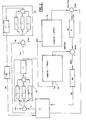
- FIG. 1 shows a gas fired boiler, generally indicated with B, comprising an airtight combustion chamber 1 in which a gas burner 2 is arranged and gas supplied via an ON-OFF valve 3 mounted on the gas supply pipe.
- An electrically controlled modulating valve MV is arranged downstream from the ON-OFF valve 3 for the purpose of modulating the gas flow rate.
- a finned heat exchanger 4 is placed above the gas burner 2. Overhead the gas burner 2 and the heat exchanger 4 a hood 5 is provided with a suction fan 6 for drawing fumes from the combustion chamber and expelling them via an exhaust pipe 7.
- the suction fan 6 also sucks ambient air from the outside via a suction pipe 8 arranged coaxially to the pipe 7 and supplies it to the combustion chamber 1 in order to sustain the combustion.
- the fan 6 is operated at adjustable speed by means of a variable-speed motor FM.
- a pipe 9 forming the heating circuit passes through the heat exchanger 4 for heating the heating water (primary heat exchanger).
- the heating water is supplied via a delivery pipe 10 and returns to the gas fired boiler via a return pipe 11.
- the pipe 9 embodies a circulation pump 12 and a three-way valve 13.
- a pipe 14 forming the circuit for the sanitary water (secondary circuit) and passing through the heat exchanger 15 for heating the sanitary water (secondary heat exchanger) departs from the three-way valve 13.
- Sanitary water is supplied to the secondary heat exchanger 15 via a pipe 16 and after being heated it is delivered via a pipe 17 for usage.
- the function of the combined gas-air control system of the invention is to control the gas and air flow rates in the gas fired boiler B in order to hold either the heating water temperature or the sanitary water temperature to a desired value which will be referred to in the following as set point temperature.
- Another function of the combined gas-air control system of the invention is to improve combustion and reduce emission of harmful combustion products in gas fired boilers.
- the combined gas-air control system of the invention comprises a microcontroller ⁇ C for operating the modulating valve MV and for adjusting the speed of the variable-speed motor FM.
- the output control signals transmitted from the ⁇ C to the modulating valve MV and the variable-speed motor FM are indicated with I mod and V f and they correspond to the control current of the modulating valve MV and to the control voltage of the variable-speed motor FM, respectively.
- the gas flow rate Q g and the air flow rate Q a are controlled so as to change combustion process conditions in the gas fired boiler B and to bring the heating or sanitary water temperature back to the set point predetermined by the user.
- Q g and Q a will be referred to in the following as manipulated variables.
- the set point temperatures of the heating and sanitary water are set typically by means of potentiometers R h and R s , respectively and the corresponding set point input signals T hr and T sr are supplied to the microcontroller ⁇ C.
- Feedback informations relating to the heating water and sanitary water temperatures, the air pressure in the combustion chamber 1 and the combustion process conditions in the burner 2 are sensed by appropriate sensors and transmitted to the microcontroller ⁇ C.
- temperature measuring means 18, 19 embodying standard temperature sensors are provided for measuring the heating water and the sanitary water temperatures, respectively
- air pressure measuring means 20 embodying a standard pressure sensor are provided for measuring the air pressure in the combustion chamber
- an ionisation electrode 21 arranged in the flame area of the burner is provided for measuring the voltage across the ionisation electrode as a function of the ionisation current through the ionisation electrode depending on the combustion process conditions of the burner 2.
- the feedback signals transmitted from the measuring means 18, 19, 20 and 21 to the microcontroller ⁇ C are indicated with T h , T s , P a and V ion respectively.
- lines represent signals
- a circle is an algebraic summing point representing addition or subtraction of input signals to the point
- rectangles are system elements and a line branching from another line indicates a division of the signal into more than one path without modification.
- the controlled variables are the heating and the sanitary water temperatures, the air pressure in the combustion chamber and the voltage across the ionisation electrode.
- Feedback signals T h , T s , P a and V ion proportional to the values of the controlled variables are applied to the microcontroller ⁇ C for processing.
- Control signals V f and I mod from the microcontroller ⁇ C are transmitted to the variable-speed motor FM and the modulating valve MV and control of the manipulated variables Q a and Q g in response to said control signals is thereby obtained.
- the control element 22 in response to the error signal E(T) sequentially performs a proportional+integral+derivative (PID) control mode and a proportional (P) control mode.
- PID proportional+integral+derivative
- Said control element 23 performs in sequence a PID control mode and P control mode and adjusts the control voltage V f applied to the variable-speed motor FM so as to change the manipulated variable Q a , i.e. the air flow rate, in response to the error signal E(P).
- the output signal P ac from the control element 22 is also applied to processing elements 24 and 25 which calculate the theoretical values of the voltage across the ionisation electrode and of the modulating valve current dependent on the corrected air pressure value.
- each processing element 24 and 25 embodies a memory in which the optimal relationships between the voltage across the ionisation electrode and the modulating valve current, respectively and the air pressure in the combustion chamber are stored.
- the output signals from the processing elements 24 and 25 are indicated with V ion(th) and I mod(th) , respectively.
- the control element 26 performs a P control mode and determines a corrected value of the control current in the modulating valve MV.
- Operation of the burner is also monitored by a thermostat 27 arranged in the burner area and connected to the ⁇ C.
- the thermostat 27 signals the malfunctioning to the ⁇ C which then shuts down the burner.
- the rpm of the fan motor and the modulating valve current can be adjusted for ensuring the required air Q a and gas Q g flow rates according to the set point temperatures of the heating or sanitary water that is delivered to usage.
- a change in the rpm of the fan motor and in the throttle of the modulating valve will occur.
- operation of the burner is also automatically adjusted by control element 26 when the type of gas supplied to the burner changes.
- the combined gas-air control system of the invention ensures optimal operation of the gas fired boiler with respect to NOx and CO emissions and efficiency.
Landscapes
- Engineering & Computer Science (AREA)
- Chemical & Material Sciences (AREA)
- Combustion & Propulsion (AREA)
- Mechanical Engineering (AREA)
- General Engineering & Computer Science (AREA)
- Regulation And Control Of Combustion (AREA)
Claims (6)
- Système de régulation combinée air-gaz pour une chaudière à gaz (B) chauffée par un brûleur (2) dans une chambre de combustion (1) comprenant :caractérisé en ce que ledit microcontrôleur (µC) comprend :un microcontrôleur (µC) avec des moyens de mémoire,des moyens formant sélecteurs (Rh, Rs) pour prédéterminer des températures de points de réglage Trh, et Trs de l'eau de chauffage et sanitaire respectivement,des moyens de mesure (18, 19, 20, 21) fournissant les signaux Th, Ts, Pa et Vion correspondant à la température de l'eau de chauffage et sanitaire, la pression d'air dans la chambre de combustion (1) et la tension d'ionisation dans la zone de flammes du brûleur (2) respectivement et pour que lesdits signaux soient communiqués en retour au microcontrôleur (µC),un thermostat (27) pour commander le fonctionnement du brûleur et pour éviter sa surchauffe,un ventilateur (6) actionné par un moteur à vitesse variable (FM) pour commander la vitesse d'écoulement Qa de l'air qui alimente la chambre de combustion (1),une vanne modulante (MV) commandée électriquement pour moduler la vitesse d'écoulement Qg de l'air qui alimente le brûleur (2),des premiers moyens de régulation (22) pour produire une action correctrice en réponse à un signal d'erreur E(T)=Trh-Th ou E(T)=Trs-Ts et pour donner un signal de sortie Pac correspondant à une valeur corrigée de pression d'air dans la chambre de combustion (1),des deuxièmes moyens de régulation (23) pour produire une action correctrice en réponse à un signal d'erreur E(P)=Pac-Pa et pour régler la tension de commande Vf appliquée au moteur à vitesse variable (FM),des moyens de traitement (24, 25) pour calculer les valeurs optimales théoriques de la tension d'ionisation et le courant de la vanne modulante en réponse au signal de sortie Pac desdits premiers moyens de régulation (22) et pour produire lesdites valeurs théoriques comme signaux de sortie Vion(th) et Imod(th), respectivement,des troisièmes moyens de régulation (26) pour produire une action correctrice en réponse à un signal d'erreur E(V)=Vion(th)-Vion et pour donner un signal de sortie Imodc correspondant à une valeur corrigée du courant de la vanne modulante, ledit signal de sortie Imodc à partir desdits troisièmes moyens de régulation (26) étant ajouté au signal de sortie Imod(th) à partir desdits moyens de traitement (25) et le signal de la somme résultante Imods=Imodc+Imod(th) étant appliqué à la vanne modulante (MV).
- Système de régulation combinée air-gaz selon la revendication 1, caractérisé en ce que l'action correctrice desdits premiers (22) et deuxièmes (23) moyens de régulation en réponse aux signaux d'erreur d'entrée respectifs E(T) et E(P) réalise conjointement un mode de régulation proportionnelle+par intégration+par dérivation et un mode de régulation proportionnelle.
- Système de régulation combinée air-gaz selon la revendication 1, caractérisé en ce que l'action correctrice desdits troisièmes moyens de régulation (26) en réponse au signal d'erreur d'entrée E(V) réalise un mode de commande proportionnelle.
- Système de régulation combinée air-gaz selon la revendication 1, caractérisé en ce que dans ledit microcontrôleur (µC), les relations optimales entre la tension à travers l'électrode d'ionisation et le courant de la vanne modulante, respectivement, et la pression d'air dans la chambre de combustion sont stockées.
- Système de régulation air-gaz combinés selon la revendication 1, caractérisé en ce que ledit microcontrôleur (µC) est de préférence un microcontrôleur numérique pourvu de moyens de conversion standard A/D et D/A.
- Système de régulation combinée air-gaz selon la revendication 1, caractérisé en ce que lesdits troisièmes moyens de régulation (26) fournissent un réglage automatique du fonctionnement du brûleur lorsque le type de gaz qui alimente le brûleur change.
Priority Applications (4)
| Application Number | Priority Date | Filing Date | Title |
|---|---|---|---|
| EP97830520A EP0909922B1 (fr) | 1997-10-17 | 1997-10-17 | Système de commande combinée à gaz et à air pour commander la combustion d'une chaudière à gaz |
| AT97830520T ATE211809T1 (de) | 1997-10-17 | 1997-10-17 | Kombiniertes regelsystem für gas und luft zur verbrennungsregelung eines gasheizkessels |
| DE69709928T DE69709928T2 (de) | 1997-10-17 | 1997-10-17 | Kombiniertes Regelsystem für Gas und Luft zur Verbrennungsregelung eines Gasheizkessels |
| ES97830520T ES2170360T3 (es) | 1997-10-17 | 1997-10-17 | Sistema de regulacion combinada de gas y de aire para regular la combustion en calderas caldeadas por gas. |
Applications Claiming Priority (1)
| Application Number | Priority Date | Filing Date | Title |
|---|---|---|---|
| EP97830520A EP0909922B1 (fr) | 1997-10-17 | 1997-10-17 | Système de commande combinée à gaz et à air pour commander la combustion d'une chaudière à gaz |
Publications (2)
| Publication Number | Publication Date |
|---|---|
| EP0909922A1 EP0909922A1 (fr) | 1999-04-21 |
| EP0909922B1 true EP0909922B1 (fr) | 2002-01-09 |
Family
ID=8230812
Family Applications (1)
| Application Number | Title | Priority Date | Filing Date |
|---|---|---|---|
| EP97830520A Expired - Lifetime EP0909922B1 (fr) | 1997-10-17 | 1997-10-17 | Système de commande combinée à gaz et à air pour commander la combustion d'une chaudière à gaz |
Country Status (4)
| Country | Link |
|---|---|
| EP (1) | EP0909922B1 (fr) |
| AT (1) | ATE211809T1 (fr) |
| DE (1) | DE69709928T2 (fr) |
| ES (1) | ES2170360T3 (fr) |
Cited By (3)
| Publication number | Priority date | Publication date | Assignee | Title |
|---|---|---|---|---|
| JP2001355841A (ja) * | 2000-05-12 | 2001-12-26 | Siemens Building Technologies Ag | バーナー用制御装置及びその制御装置の設定方法 |
| CN102640978A (zh) * | 2012-05-11 | 2012-08-22 | 云南省烟草农业科学研究院 | 双压引风加热装置 |
| CN102777886A (zh) * | 2012-08-13 | 2012-11-14 | 中国中元国际工程公司 | 燃气锅炉烟气余热回收装置和方法 |
Families Citing this family (13)
| Publication number | Priority date | Publication date | Assignee | Title |
|---|---|---|---|---|
| DE69920158T2 (de) * | 1999-02-03 | 2005-10-20 | Riello S.P.A., Legnago | Gas Regelanlage |
| ES2240007T3 (es) * | 2000-03-03 | 2005-10-16 | Riello S.P.A. | Caldera de gas. |
| ATE350625T1 (de) * | 2000-03-03 | 2007-01-15 | Riello Spa | Regelanlage für kessel |
| NL1015797C2 (nl) | 2000-07-25 | 2002-01-28 | Nefit Buderus B V | Verbrandingsinrichting en werkwijze voor het besturen van een verbrandingsinrichting. |
| EP1351019B1 (fr) | 2002-04-02 | 2013-07-17 | Siemens Schweiz AG | Procédé pour le contrôle du fonctionnement d'un système de régulation de brûleur pour appareil de chauffage |
| ITAN20020038A1 (it) * | 2002-08-05 | 2004-02-06 | Merloni Termosanitari Spa Ora Ariston Thermo Spa | Sistema di controllo della combustione a sensore virtuale di lambda. |
| ITAN20020035U1 (it) * | 2002-12-23 | 2004-06-24 | Merloni Termosanitari Spa Ora Ariston Thermo Spa | Pressostato universale per caldaie a camera stagna e tiraggio forzato |
| ITAN20020062A1 (it) * | 2002-12-23 | 2004-06-24 | Merloni Termosanitari Spa Ora Ariston Thermo Spa | Caldaia murale a tiraggio forzato polivalente. |
| CN1332152C (zh) * | 2003-04-11 | 2007-08-15 | 株式会社庆东纳碧安 | 使用空气压力传感器的空气比例式锅炉 |
| KR20060087071A (ko) * | 2005-01-28 | 2006-08-02 | 주식회사 경동네트웍 | 풍량센서를 이용한 오일 버너의 적정 공연비 제어 시스템및 그 제어방법 |
| EP1712841A1 (fr) * | 2005-04-14 | 2006-10-18 | Immergas S.p.A. | Dispositif électronique et procédé pour contrôler l'évacuation des gaz brûlés, en particulier dans une chaudière |
| WO2008017177A1 (fr) * | 2006-08-10 | 2008-02-14 | Toby Ag | Procédé de réglage d'un brûleur |
| CN112161292A (zh) * | 2020-09-14 | 2021-01-01 | 华帝股份有限公司 | 一种燃烧系统燃烧状态控制方法及应用其的热水器 |
Family Cites Families (6)
| Publication number | Priority date | Publication date | Assignee | Title |
|---|---|---|---|---|
| JPH0674891B2 (ja) * | 1988-04-27 | 1994-09-21 | リンナイ株式会社 | 強制送風式燃焼装置 |
| JPH02161208A (ja) * | 1988-12-14 | 1990-06-21 | Harman Co Ltd | 燃焼装置 |
| AT397851B (de) * | 1989-11-24 | 1994-07-25 | Vaillant Gmbh | Heizgerät |
| JP3366394B2 (ja) * | 1993-09-02 | 2003-01-14 | 株式会社ガスター | 燃焼装置及び燃焼制御方法 |
| DE19618573C1 (de) * | 1996-05-09 | 1997-06-26 | Stiebel Eltron Gmbh & Co Kg | Verfahren und Einrichtung zum Betrieb eines Gasbrenners |
| DE19601517B4 (de) * | 1996-01-17 | 2006-01-19 | Stiebel Eltron Gmbh & Co. Kg | Regelung eines Gasheizgeräts |
-
1997
- 1997-10-17 ES ES97830520T patent/ES2170360T3/es not_active Expired - Lifetime
- 1997-10-17 DE DE69709928T patent/DE69709928T2/de not_active Expired - Lifetime
- 1997-10-17 EP EP97830520A patent/EP0909922B1/fr not_active Expired - Lifetime
- 1997-10-17 AT AT97830520T patent/ATE211809T1/de active
Cited By (4)
| Publication number | Priority date | Publication date | Assignee | Title |
|---|---|---|---|---|
| JP2001355841A (ja) * | 2000-05-12 | 2001-12-26 | Siemens Building Technologies Ag | バーナー用制御装置及びその制御装置の設定方法 |
| CN102640978A (zh) * | 2012-05-11 | 2012-08-22 | 云南省烟草农业科学研究院 | 双压引风加热装置 |
| CN102777886A (zh) * | 2012-08-13 | 2012-11-14 | 中国中元国际工程公司 | 燃气锅炉烟气余热回收装置和方法 |
| CN102777886B (zh) * | 2012-08-13 | 2014-07-16 | 中国中元国际工程公司 | 燃气锅炉烟气余热回收装置和方法 |
Also Published As
| Publication number | Publication date |
|---|---|
| ATE211809T1 (de) | 2002-01-15 |
| ES2170360T3 (es) | 2002-08-01 |
| EP0909922A1 (fr) | 1999-04-21 |
| DE69709928T2 (de) | 2002-08-29 |
| DE69709928D1 (de) | 2002-02-28 |
Similar Documents
| Publication | Publication Date | Title |
|---|---|---|
| EP0909922B1 (fr) | Système de commande combinée à gaz et à air pour commander la combustion d'une chaudière à gaz | |
| EP0322132B1 (fr) | Dispositif à brûleur au fuel et une méthode de contrôle | |
| AU720035B2 (en) | Modulating furnace with two-speed draft inducer | |
| US5248083A (en) | Adaptive furnace control using analog temperature sensing | |
| US5865611A (en) | Fuel-fired modulating furnace calibration apparatus and methods | |
| US5307990A (en) | Adaptive forced warm air furnace using analog temperature and pressure sensors | |
| US4695052A (en) | Hot water heating system using a heat consumption meter | |
| JP2808736B2 (ja) | 給湯器の制御装置 | |
| JPH07310918A (ja) | 比例弁付き燃焼器具およびその比例弁調整装置 | |
| JP2669771B2 (ja) | 燃焼装置 | |
| JP2612985B2 (ja) | バーナ制御装置 | |
| JP2000161780A (ja) | 給湯装置 | |
| JP3018811B2 (ja) | 燃焼制御装置 | |
| JP2669662B2 (ja) | 給湯機の制御装置 | |
| JP3122525B2 (ja) | 燃焼装置およびその燃焼制御方法 | |
| JPH0745930B2 (ja) | ガス燃焼機器の空燃比制御装置 | |
| JPH0350184B2 (fr) | ||
| EP1130320A1 (fr) | Système de commande pour chaudières | |
| JPH0440607B2 (fr) | ||
| KR100292457B1 (ko) | 공기비례제어식비콘덴싱보일러 | |
| JP2513638Y2 (ja) | 送風機の酸素一定制御機構 | |
| JPH01150741A (ja) | 給湯機の出湯温度制御装置 | |
| JPH07253211A (ja) | ファンの制御装置 | |
| JPH0996417A (ja) | 給湯機の制御装置 | |
| JPH02287013A (ja) | 燃焼制御装置 |
Legal Events
| Date | Code | Title | Description |
|---|---|---|---|
| PUAI | Public reference made under article 153(3) epc to a published international application that has entered the european phase |
Free format text: ORIGINAL CODE: 0009012 |
|
| 17P | Request for examination filed |
Effective date: 19980707 |
|
| AK | Designated contracting states |
Kind code of ref document: A1 Designated state(s): AT DE ES FR GB IT |
|
| AX | Request for extension of the european patent |
Free format text: AL;LT;LV;RO;SI |
|
| AKX | Designation fees paid |
Free format text: AT DE ES FR GB IT |
|
| 17Q | First examination report despatched |
Effective date: 19991217 |
|
| GRAG | Despatch of communication of intention to grant |
Free format text: ORIGINAL CODE: EPIDOS AGRA |
|
| GRAG | Despatch of communication of intention to grant |
Free format text: ORIGINAL CODE: EPIDOS AGRA |
|
| GRAH | Despatch of communication of intention to grant a patent |
Free format text: ORIGINAL CODE: EPIDOS IGRA |
|
| RAP1 | Party data changed (applicant data changed or rights of an application transferred) |
Owner name: RIELLO S.P.A. |
|
| GRAH | Despatch of communication of intention to grant a patent |
Free format text: ORIGINAL CODE: EPIDOS IGRA |
|
| GRAA | (expected) grant |
Free format text: ORIGINAL CODE: 0009210 |
|
| REG | Reference to a national code |
Ref country code: GB Ref legal event code: IF02 |
|
| AK | Designated contracting states |
Kind code of ref document: B1 Designated state(s): AT DE ES FR GB IT |
|
| REF | Corresponds to: |
Ref document number: 211809 Country of ref document: AT Date of ref document: 20020115 Kind code of ref document: T |
|
| REF | Corresponds to: |
Ref document number: 69709928 Country of ref document: DE Date of ref document: 20020228 |
|
| ET | Fr: translation filed | ||
| REG | Reference to a national code |
Ref country code: ES Ref legal event code: FG2A Ref document number: 2170360 Country of ref document: ES Kind code of ref document: T3 |
|
| PLBI | Opposition filed |
Free format text: ORIGINAL CODE: 0009260 |
|
| PLBF | Reply of patent proprietor to notice(s) of opposition |
Free format text: ORIGINAL CODE: EPIDOS OBSO |
|
| 26 | Opposition filed |
Opponent name: STIEBEL ELTRON GMBH & CO.KG Effective date: 20021009 |
|
| PLBF | Reply of patent proprietor to notice(s) of opposition |
Free format text: ORIGINAL CODE: EPIDOS OBSO |
|
| PLBF | Reply of patent proprietor to notice(s) of opposition |
Free format text: ORIGINAL CODE: EPIDOS OBSO |
|
| PLCK | Communication despatched that opposition was rejected |
Free format text: ORIGINAL CODE: EPIDOSNREJ1 |
|
| APBP | Date of receipt of notice of appeal recorded |
Free format text: ORIGINAL CODE: EPIDOSNNOA2O |
|
| APBM | Appeal reference recorded |
Free format text: ORIGINAL CODE: EPIDOSNREFNO |
|
| APBQ | Date of receipt of statement of grounds of appeal recorded |
Free format text: ORIGINAL CODE: EPIDOSNNOA3O |
|
| APAH | Appeal reference modified |
Free format text: ORIGINAL CODE: EPIDOSCREFNO |
|
| REG | Reference to a national code |
Ref country code: GB Ref legal event code: 732E |
|
| REG | Reference to a national code |
Ref country code: FR Ref legal event code: GC |
|
| APBU | Appeal procedure closed |
Free format text: ORIGINAL CODE: EPIDOSNNOA9O |
|
| PLBN | Opposition rejected |
Free format text: ORIGINAL CODE: 0009273 |
|
| STAA | Information on the status of an ep patent application or granted ep patent |
Free format text: STATUS: OPPOSITION REJECTED |
|
| 27O | Opposition rejected |
Effective date: 20070328 |
|
| REG | Reference to a national code |
Ref country code: FR Ref legal event code: PLFP Year of fee payment: 20 |
|
| REG | Reference to a national code |
Ref country code: FR Ref legal event code: RG Effective date: 20161115 |
|
| PGFP | Annual fee paid to national office [announced via postgrant information from national office to epo] |
Ref country code: FR Payment date: 20161027 Year of fee payment: 20 Ref country code: GB Payment date: 20161028 Year of fee payment: 20 |
|
| PGFP | Annual fee paid to national office [announced via postgrant information from national office to epo] |
Ref country code: AT Payment date: 20161027 Year of fee payment: 20 Ref country code: IT Payment date: 20161007 Year of fee payment: 20 Ref country code: ES Payment date: 20161125 Year of fee payment: 20 |
|
| PGFP | Annual fee paid to national office [announced via postgrant information from national office to epo] |
Ref country code: DE Payment date: 20170102 Year of fee payment: 20 |
|
| REG | Reference to a national code |
Ref country code: DE Ref legal event code: R071 Ref document number: 69709928 Country of ref document: DE |
|
| REG | Reference to a national code |
Ref country code: GB Ref legal event code: PE20 Expiry date: 20171016 |
|
| REG | Reference to a national code |
Ref country code: AT Ref legal event code: MK07 Ref document number: 211809 Country of ref document: AT Kind code of ref document: T Effective date: 20171017 |
|
| PG25 | Lapsed in a contracting state [announced via postgrant information from national office to epo] |
Ref country code: GB Free format text: LAPSE BECAUSE OF EXPIRATION OF PROTECTION Effective date: 20171016 |
|
| REG | Reference to a national code |
Ref country code: ES Ref legal event code: FD2A Effective date: 20180508 |
|
| REG | Reference to a national code |
Ref country code: DE Ref legal event code: R082 Ref document number: 69709928 Country of ref document: DE Representative=s name: SCHOEN, THILO, DIPL.-PHYS., DE |
|
| PG25 | Lapsed in a contracting state [announced via postgrant information from national office to epo] |
Ref country code: ES Free format text: LAPSE BECAUSE OF EXPIRATION OF PROTECTION Effective date: 20171018 |