EP0909845B1 - A woven carbon fiber fabric, a fiber reinforced plastic molding obtained by using the woven fabric, and a production method of the molding - Google Patents
A woven carbon fiber fabric, a fiber reinforced plastic molding obtained by using the woven fabric, and a production method of the molding Download PDFInfo
- Publication number
- EP0909845B1 EP0909845B1 EP98114188A EP98114188A EP0909845B1 EP 0909845 B1 EP0909845 B1 EP 0909845B1 EP 98114188 A EP98114188 A EP 98114188A EP 98114188 A EP98114188 A EP 98114188A EP 0909845 B1 EP0909845 B1 EP 0909845B1
- Authority
- EP
- European Patent Office
- Prior art keywords
- carbon fiber
- woven
- fabric
- resin
- yarns
- Prior art date
- Legal status (The legal status is an assumption and is not a legal conclusion. Google has not performed a legal analysis and makes no representation as to the accuracy of the status listed.)
- Expired - Lifetime
Links
- 229920000049 Carbon (fiber) Polymers 0.000 title claims description 276
- 239000004917 carbon fiber Substances 0.000 title claims description 272
- VNWKTOKETHGBQD-UHFFFAOYSA-N methane Chemical compound C VNWKTOKETHGBQD-UHFFFAOYSA-N 0.000 title claims description 252
- 239000004744 fabric Substances 0.000 title claims description 149
- 238000000465 moulding Methods 0.000 title claims description 120
- 229920002430 Fibre-reinforced plastic Polymers 0.000 title claims description 44
- 239000011151 fibre-reinforced plastic Substances 0.000 title claims description 44
- 238000010137 moulding (plastic) Methods 0.000 title claims description 32
- 238000004519 manufacturing process Methods 0.000 title claims description 21
- 239000002759 woven fabric Substances 0.000 title description 144
- 229920005989 resin Polymers 0.000 claims description 170
- 239000011347 resin Substances 0.000 claims description 170
- 239000002657 fibrous material Substances 0.000 claims description 87
- OKTJSMMVPCPJKN-UHFFFAOYSA-N Carbon Chemical compound [C] OKTJSMMVPCPJKN-UHFFFAOYSA-N 0.000 claims description 21
- 229910052799 carbon Inorganic materials 0.000 claims description 21
- 238000009792 diffusion process Methods 0.000 claims description 21
- 229920000642 polymer Polymers 0.000 claims description 21
- 230000008018 melting Effects 0.000 claims description 19
- 238000002844 melting Methods 0.000 claims description 19
- 239000011159 matrix material Substances 0.000 claims description 9
- 239000000463 material Substances 0.000 claims description 3
- 238000007599 discharging Methods 0.000 claims 1
- 239000000835 fiber Substances 0.000 description 27
- 238000000034 method Methods 0.000 description 27
- 239000004918 carbon fiber reinforced polymer Substances 0.000 description 20
- 239000003365 glass fiber Substances 0.000 description 15
- 238000005470 impregnation Methods 0.000 description 15
- 230000000052 comparative effect Effects 0.000 description 12
- 239000004952 Polyamide Substances 0.000 description 11
- 229920002647 polyamide Polymers 0.000 description 11
- 239000003795 chemical substances by application Substances 0.000 description 10
- -1 copolyamides Polymers 0.000 description 8
- 238000002347 injection Methods 0.000 description 8
- 239000007924 injection Substances 0.000 description 8
- 239000000565 sealant Substances 0.000 description 8
- 229920000742 Cotton Polymers 0.000 description 7
- 238000005520 cutting process Methods 0.000 description 7
- 238000003475 lamination Methods 0.000 description 7
- 229920000728 polyester Polymers 0.000 description 7
- 238000004513 sizing Methods 0.000 description 7
- 238000001721 transfer moulding Methods 0.000 description 7
- 229920001567 vinyl ester resin Polymers 0.000 description 7
- 239000006260 foam Substances 0.000 description 6
- 238000010030 laminating Methods 0.000 description 6
- 239000012783 reinforcing fiber Substances 0.000 description 6
- 238000009941 weaving Methods 0.000 description 6
- 239000004800 polyvinyl chloride Substances 0.000 description 5
- 229920000915 polyvinyl chloride Polymers 0.000 description 5
- 239000004698 Polyethylene Substances 0.000 description 4
- 230000000694 effects Effects 0.000 description 4
- 239000012466 permeate Substances 0.000 description 4
- 229920000573 polyethylene Polymers 0.000 description 4
- 239000004743 Polypropylene Substances 0.000 description 3
- 229920003235 aromatic polyamide Polymers 0.000 description 3
- 238000009787 hand lay-up Methods 0.000 description 3
- 238000005259 measurement Methods 0.000 description 3
- 239000005011 phenolic resin Substances 0.000 description 3
- 229920001155 polypropylene Polymers 0.000 description 3
- VTYYLEPIZMXCLO-UHFFFAOYSA-L Calcium carbonate Chemical compound [Ca+2].[O-]C([O-])=O VTYYLEPIZMXCLO-UHFFFAOYSA-L 0.000 description 2
- 239000003822 epoxy resin Substances 0.000 description 2
- LNEPOXFFQSENCJ-UHFFFAOYSA-N haloperidol Chemical compound C1CC(O)(C=2C=CC(Cl)=CC=2)CCN1CCCC(=O)C1=CC=C(F)C=C1 LNEPOXFFQSENCJ-UHFFFAOYSA-N 0.000 description 2
- 239000012299 nitrogen atmosphere Substances 0.000 description 2
- 230000001590 oxidative effect Effects 0.000 description 2
- 229920003023 plastic Polymers 0.000 description 2
- 239000004033 plastic Substances 0.000 description 2
- 229920002239 polyacrylonitrile Polymers 0.000 description 2
- 229920000647 polyepoxide Polymers 0.000 description 2
- 229920002635 polyurethane Polymers 0.000 description 2
- 239000004814 polyurethane Substances 0.000 description 2
- 229920001187 thermosetting polymer Polymers 0.000 description 2
- 229920006337 unsaturated polyester resin Polymers 0.000 description 2
- 239000004925 Acrylic resin Substances 0.000 description 1
- 229920000178 Acrylic resin Polymers 0.000 description 1
- 229920001634 Copolyester Polymers 0.000 description 1
- ISWSIDIOOBJBQZ-UHFFFAOYSA-N Phenol Chemical compound OC1=CC=CC=C1 ISWSIDIOOBJBQZ-UHFFFAOYSA-N 0.000 description 1
- 239000004696 Poly ether ether ketone Substances 0.000 description 1
- 239000004734 Polyphenylene sulfide Substances 0.000 description 1
- 239000004793 Polystyrene Substances 0.000 description 1
- 229920001328 Polyvinylidene chloride Polymers 0.000 description 1
- 229920000122 acrylonitrile butadiene styrene Polymers 0.000 description 1
- 239000000853 adhesive Substances 0.000 description 1
- 230000001070 adhesive effect Effects 0.000 description 1
- 239000012298 atmosphere Substances 0.000 description 1
- 230000002457 bidirectional effect Effects 0.000 description 1
- 238000007664 blowing Methods 0.000 description 1
- 229910000019 calcium carbonate Inorganic materials 0.000 description 1
- 229910052918 calcium silicate Inorganic materials 0.000 description 1
- 239000000378 calcium silicate Substances 0.000 description 1
- OYACROKNLOSFPA-UHFFFAOYSA-N calcium;dioxido(oxo)silane Chemical compound [Ca+2].[O-][Si]([O-])=O OYACROKNLOSFPA-UHFFFAOYSA-N 0.000 description 1
- 238000003763 carbonization Methods 0.000 description 1
- 238000010000 carbonizing Methods 0.000 description 1
- 230000001112 coagulating effect Effects 0.000 description 1
- 239000002131 composite material Substances 0.000 description 1
- 230000007423 decrease Effects 0.000 description 1
- 230000008021 deposition Effects 0.000 description 1
- 238000011161 development Methods 0.000 description 1
- 230000018109 developmental process Effects 0.000 description 1
- 230000002708 enhancing effect Effects 0.000 description 1
- ZINJLDJMHCUBIP-UHFFFAOYSA-N ethametsulfuron-methyl Chemical compound CCOC1=NC(NC)=NC(NC(=O)NS(=O)(=O)C=2C(=CC=CC=2)C(=O)OC)=N1 ZINJLDJMHCUBIP-UHFFFAOYSA-N 0.000 description 1
- 230000005484 gravity Effects 0.000 description 1
- 238000010438 heat treatment Methods 0.000 description 1
- ZFSLODLOARCGLH-UHFFFAOYSA-N isocyanuric acid Chemical compound OC1=NC(O)=NC(O)=N1 ZFSLODLOARCGLH-UHFFFAOYSA-N 0.000 description 1
- 239000007788 liquid Substances 0.000 description 1
- 229910052751 metal Inorganic materials 0.000 description 1
- 239000002184 metal Substances 0.000 description 1
- 150000002739 metals Chemical class 0.000 description 1
- 239000000203 mixture Substances 0.000 description 1
- 230000002093 peripheral effect Effects 0.000 description 1
- 229920001568 phenolic resin Polymers 0.000 description 1
- 229920006122 polyamide resin Polymers 0.000 description 1
- 229920006267 polyester film Polymers 0.000 description 1
- 229920001225 polyester resin Polymers 0.000 description 1
- 239000004645 polyester resin Substances 0.000 description 1
- 229920002530 polyetherether ketone Polymers 0.000 description 1
- 229920013716 polyethylene resin Polymers 0.000 description 1
- 229920000069 polyphenylene sulfide Polymers 0.000 description 1
- 229920001296 polysiloxane Polymers 0.000 description 1
- 229920002223 polystyrene Polymers 0.000 description 1
- 239000005033 polyvinylidene chloride Substances 0.000 description 1
- 239000002243 precursor Substances 0.000 description 1
- 238000002360 preparation method Methods 0.000 description 1
- 239000011371 regular concrete Substances 0.000 description 1
- 229920005992 thermoplastic resin Polymers 0.000 description 1
Images
Classifications
-
- D—TEXTILES; PAPER
- D03—WEAVING
- D03D—WOVEN FABRICS; METHODS OF WEAVING; LOOMS
- D03D15/00—Woven fabrics characterised by the material, structure or properties of the fibres, filaments, yarns, threads or other warp or weft elements used
- D03D15/20—Woven fabrics characterised by the material, structure or properties of the fibres, filaments, yarns, threads or other warp or weft elements used characterised by the material of the fibres or filaments constituting the yarns or threads
- D03D15/242—Woven fabrics characterised by the material, structure or properties of the fibres, filaments, yarns, threads or other warp or weft elements used characterised by the material of the fibres or filaments constituting the yarns or threads inorganic, e.g. basalt
- D03D15/275—Carbon fibres
-
- B—PERFORMING OPERATIONS; TRANSPORTING
- B29—WORKING OF PLASTICS; WORKING OF SUBSTANCES IN A PLASTIC STATE IN GENERAL
- B29C—SHAPING OR JOINING OF PLASTICS; SHAPING OF MATERIAL IN A PLASTIC STATE, NOT OTHERWISE PROVIDED FOR; AFTER-TREATMENT OF THE SHAPED PRODUCTS, e.g. REPAIRING
- B29C70/00—Shaping composites, i.e. plastics material comprising reinforcements, fillers or preformed parts, e.g. inserts
- B29C70/04—Shaping composites, i.e. plastics material comprising reinforcements, fillers or preformed parts, e.g. inserts comprising reinforcements only, e.g. self-reinforcing plastics
- B29C70/06—Fibrous reinforcements only
- B29C70/10—Fibrous reinforcements only characterised by the structure of fibrous reinforcements, e.g. hollow fibres
- B29C70/16—Fibrous reinforcements only characterised by the structure of fibrous reinforcements, e.g. hollow fibres using fibres of substantial or continuous length
- B29C70/22—Fibrous reinforcements only characterised by the structure of fibrous reinforcements, e.g. hollow fibres using fibres of substantial or continuous length oriented in at least two directions forming a two dimensional structure
-
- B—PERFORMING OPERATIONS; TRANSPORTING
- B29—WORKING OF PLASTICS; WORKING OF SUBSTANCES IN A PLASTIC STATE IN GENERAL
- B29C—SHAPING OR JOINING OF PLASTICS; SHAPING OF MATERIAL IN A PLASTIC STATE, NOT OTHERWISE PROVIDED FOR; AFTER-TREATMENT OF THE SHAPED PRODUCTS, e.g. REPAIRING
- B29C70/00—Shaping composites, i.e. plastics material comprising reinforcements, fillers or preformed parts, e.g. inserts
- B29C70/04—Shaping composites, i.e. plastics material comprising reinforcements, fillers or preformed parts, e.g. inserts comprising reinforcements only, e.g. self-reinforcing plastics
- B29C70/28—Shaping operations therefor
- B29C70/40—Shaping or impregnating by compression not applied
- B29C70/42—Shaping or impregnating by compression not applied for producing articles of definite length, i.e. discrete articles
- B29C70/44—Shaping or impregnating by compression not applied for producing articles of definite length, i.e. discrete articles using isostatic pressure, e.g. pressure difference-moulding, vacuum bag-moulding, autoclave-moulding or expanding rubber-moulding
- B29C70/443—Shaping or impregnating by compression not applied for producing articles of definite length, i.e. discrete articles using isostatic pressure, e.g. pressure difference-moulding, vacuum bag-moulding, autoclave-moulding or expanding rubber-moulding and impregnating by vacuum or injection
-
- B—PERFORMING OPERATIONS; TRANSPORTING
- B29—WORKING OF PLASTICS; WORKING OF SUBSTANCES IN A PLASTIC STATE IN GENERAL
- B29C—SHAPING OR JOINING OF PLASTICS; SHAPING OF MATERIAL IN A PLASTIC STATE, NOT OTHERWISE PROVIDED FOR; AFTER-TREATMENT OF THE SHAPED PRODUCTS, e.g. REPAIRING
- B29C70/00—Shaping composites, i.e. plastics material comprising reinforcements, fillers or preformed parts, e.g. inserts
- B29C70/04—Shaping composites, i.e. plastics material comprising reinforcements, fillers or preformed parts, e.g. inserts comprising reinforcements only, e.g. self-reinforcing plastics
- B29C70/28—Shaping operations therefor
- B29C70/54—Component parts, details or accessories; Auxiliary operations, e.g. feeding or storage of prepregs or SMC after impregnation or during ageing
- B29C70/546—Measures for feeding or distributing the matrix material in the reinforcing structure
- B29C70/548—Measures for feeding or distributing the matrix material in the reinforcing structure using distribution constructions, e.g. channels incorporated in or associated with the mould
-
- D—TEXTILES; PAPER
- D03—WEAVING
- D03D—WOVEN FABRICS; METHODS OF WEAVING; LOOMS
- D03D15/00—Woven fabrics characterised by the material, structure or properties of the fibres, filaments, yarns, threads or other warp or weft elements used
- D03D15/20—Woven fabrics characterised by the material, structure or properties of the fibres, filaments, yarns, threads or other warp or weft elements used characterised by the material of the fibres or filaments constituting the yarns or threads
- D03D15/242—Woven fabrics characterised by the material, structure or properties of the fibres, filaments, yarns, threads or other warp or weft elements used characterised by the material of the fibres or filaments constituting the yarns or threads inorganic, e.g. basalt
- D03D15/267—Glass
-
- D—TEXTILES; PAPER
- D03—WEAVING
- D03D—WOVEN FABRICS; METHODS OF WEAVING; LOOMS
- D03D15/00—Woven fabrics characterised by the material, structure or properties of the fibres, filaments, yarns, threads or other warp or weft elements used
- D03D15/50—Woven fabrics characterised by the material, structure or properties of the fibres, filaments, yarns, threads or other warp or weft elements used characterised by the properties of the yarns or threads
- D03D15/573—Tensile strength
-
- B—PERFORMING OPERATIONS; TRANSPORTING
- B29—WORKING OF PLASTICS; WORKING OF SUBSTANCES IN A PLASTIC STATE IN GENERAL
- B29K—INDEXING SCHEME ASSOCIATED WITH SUBCLASSES B29B, B29C OR B29D, RELATING TO MOULDING MATERIALS OR TO MATERIALS FOR MOULDS, REINFORCEMENTS, FILLERS OR PREFORMED PARTS, e.g. INSERTS
- B29K2307/00—Use of elements other than metals as reinforcement
-
- D—TEXTILES; PAPER
- D10—INDEXING SCHEME ASSOCIATED WITH SUBLASSES OF SECTION D, RELATING TO TEXTILES
- D10B—INDEXING SCHEME ASSOCIATED WITH SUBLASSES OF SECTION D, RELATING TO TEXTILES
- D10B2101/00—Inorganic fibres
- D10B2101/02—Inorganic fibres based on oxides or oxide ceramics, e.g. silicates
- D10B2101/06—Glass
-
- D—TEXTILES; PAPER
- D10—INDEXING SCHEME ASSOCIATED WITH SUBLASSES OF SECTION D, RELATING TO TEXTILES
- D10B—INDEXING SCHEME ASSOCIATED WITH SUBLASSES OF SECTION D, RELATING TO TEXTILES
- D10B2101/00—Inorganic fibres
- D10B2101/10—Inorganic fibres based on non-oxides other than metals
- D10B2101/12—Carbon; Pitch
-
- D—TEXTILES; PAPER
- D10—INDEXING SCHEME ASSOCIATED WITH SUBLASSES OF SECTION D, RELATING TO TEXTILES
- D10B—INDEXING SCHEME ASSOCIATED WITH SUBLASSES OF SECTION D, RELATING TO TEXTILES
- D10B2101/00—Inorganic fibres
- D10B2101/20—Metallic fibres
-
- D—TEXTILES; PAPER
- D10—INDEXING SCHEME ASSOCIATED WITH SUBLASSES OF SECTION D, RELATING TO TEXTILES
- D10B—INDEXING SCHEME ASSOCIATED WITH SUBLASSES OF SECTION D, RELATING TO TEXTILES
- D10B2201/00—Cellulose-based fibres, e.g. vegetable fibres
- D10B2201/01—Natural vegetable fibres
- D10B2201/02—Cotton
-
- D—TEXTILES; PAPER
- D10—INDEXING SCHEME ASSOCIATED WITH SUBLASSES OF SECTION D, RELATING TO TEXTILES
- D10B—INDEXING SCHEME ASSOCIATED WITH SUBLASSES OF SECTION D, RELATING TO TEXTILES
- D10B2321/00—Fibres made from polymers obtained by reactions only involving carbon-to-carbon unsaturated bonds
- D10B2321/10—Fibres made from polymers obtained by reactions only involving carbon-to-carbon unsaturated bonds polymers of unsaturated nitriles, e.g. polyacrylonitrile, polyvinylidene cyanide
-
- D—TEXTILES; PAPER
- D10—INDEXING SCHEME ASSOCIATED WITH SUBLASSES OF SECTION D, RELATING TO TEXTILES
- D10B—INDEXING SCHEME ASSOCIATED WITH SUBLASSES OF SECTION D, RELATING TO TEXTILES
- D10B2331/00—Fibres made from polymers obtained otherwise than by reactions only involving carbon-to-carbon unsaturated bonds, e.g. polycondensation products
- D10B2331/02—Fibres made from polymers obtained otherwise than by reactions only involving carbon-to-carbon unsaturated bonds, e.g. polycondensation products polyamides
- D10B2331/021—Fibres made from polymers obtained otherwise than by reactions only involving carbon-to-carbon unsaturated bonds, e.g. polycondensation products polyamides aromatic polyamides, e.g. aramides
-
- D—TEXTILES; PAPER
- D10—INDEXING SCHEME ASSOCIATED WITH SUBLASSES OF SECTION D, RELATING TO TEXTILES
- D10B—INDEXING SCHEME ASSOCIATED WITH SUBLASSES OF SECTION D, RELATING TO TEXTILES
- D10B2331/00—Fibres made from polymers obtained otherwise than by reactions only involving carbon-to-carbon unsaturated bonds, e.g. polycondensation products
- D10B2331/04—Fibres made from polymers obtained otherwise than by reactions only involving carbon-to-carbon unsaturated bonds, e.g. polycondensation products polyesters, e.g. polyethylene terephthalate [PET]
-
- D—TEXTILES; PAPER
- D10—INDEXING SCHEME ASSOCIATED WITH SUBLASSES OF SECTION D, RELATING TO TEXTILES
- D10B—INDEXING SCHEME ASSOCIATED WITH SUBLASSES OF SECTION D, RELATING TO TEXTILES
- D10B2401/00—Physical properties
- D10B2401/06—Load-responsive characteristics
- D10B2401/063—Load-responsive characteristics high strength
Definitions
- the present invention relates to a woven carbon fiber fabric, in more detail, a woven carbon fiber fabric formed by using thick carbon fiber tows respectively comprising about 40,000 to about 400,000 carbon filaments, a fiber reinforced plastic molding obtained by using the woven carbon fiber fabric, and a production method of the molding.
- Carbon fibers have a low specific gravity, high tensile strength and tensile modulus of elasticity.
- a carbon fiber reinforced plastic (CFRP) obtained by molding the carbon fibers immobilized by a resin attracts attention as a composite with a high strength and modulus of elasticity.
- the conventional CFRP uses thin carbon fiber yarns respectively comprising about 3,000 carbon filaments.
- the conventional CFRP uses a thin bi-directional woven fabric with the thin carbon fiber yarns arranged longitudinal and transverse, and with the areal unit weight of carbon fibers kept in a range of about 200 to about 400 g/m 2 .
- the conventional CFRP is produced by laminating many sheets of a prepreg formed by the thin bi-directional woven fabric impregnated with a resin, and molding the laminate in an autoclave.
- the conventional CFRP is disadvantageously high in production cost for the reasons described below. Since it is expensive though excellent in performance, it is used only in limited areas as an aircraft related structural material and a base of high quality sporting goods, and is not applied in general industrial areas.
- the conventional CFRP is expensive for the following reasons; (a) thin carbon fiber yarns are low in productivity; (b) a woven carbon fiber fabric is low in productivity, since it is produced from thin carbon fiber yarns; (c) since the obtained woven carbon fiber fabric is thin, many sheets of a woven fabric must be laminated to muster the carbon fibers necessary for producing a CFRP molding with desired properties, and in the production of CFRP, laminating many sheets of a fabric is very troublesome; (d) since the prepreg process is necessary, the cost for the prepreg process is added; and (e) an autoclave is necessary to require large equipment investment.
- a woven fabric in which carbon fiber yarns are arranged in uni direction is not lowered in strength since the yarns are not crimped; however, if the areal unit weight of carbon fibers of the woven fabric is increased, the fiber density becomes very large, to lessen the clearances between the respectively adjacent filaments, since the carbon fiber yarns are arranged in uni direction only, and the resin flow into the clearances between filaments becomes poor, taking much time for resin injection, thus lowering the resin impregnability into the woven carbon fiber fabric in such molding as resin transfer molding or vacuum bag molding.
- US-A-4 714 642 describes a bi-directional woven fabric comprising multifilamentary tows of carbon fibers, the tows comprising approximately 1,000 to 50,000 filaments.
- US-A-4 902 215 describes a plastic transfer molding technique for the production of fiber reinforced plastic structures. This reference only describes the general technique without reference to a specific woven carbon fiber fabric.
- the object of the present invention is to provide a woven carbon fiber fabric solving the problems of the above mentioned prior arts, a fiber reinforced plastic molding obtained by using said woven fabric, and a production method of said molding.
- the present invention uses thick carbon fiber tows with an intention to improve the resin impregnability of the woven carbon fiber fabric formed by the tows.
- a CFRP includes both the cases where the reinforcing fibers of the plastic consist of carbon fibers only and consist of carbon fibers and other fibers.
- the woven carbon fiber fabric as a 1st embodiment is characterized in that many carbon fiber yarns respectively comprising about 40,000 to about 400,000 filaments and having filament interlacements between the respective filaments are arranged.
- Each of the carbon fiber yarns used here is produced by oxidizing a polyacrylonitrile fiber tow comprising about 40,000 to about 400,000 filaments, treating it for carbonization, and applying a sizing agent to it for bundling the tow as a whole.
- the number of filaments of the carbon fiber yarn is less than about 40,000, it is preferable in view of the resin impregnability since the yarn is relatively thin. However, the effect of cost reduction in the production of carbon fibers is small.
- each of the carbon fiber yarns constituting a woven fabric is free from filament interlacements between its very many filaments, that is, has many filaments arranged in parallel to each other, the filaments are not bent, and so stress concentration does not occur.
- the CFRP obtained by using the yarns can manifest its strength well, and have a high strength. However, since there are substantially no clearances between the respective filaments, the filaments are densely packed, and in addition, the yarns are thick. So, the resin does not permeate the yarns to their centers disadvantageously.
- the raw yarn (polyacrylonitrile fiber yarn or precursor) of the carbon fiber yarn can have its filaments interlaced as desired by adjusting the intensity of the flow in the coagulating bath or rinsing bath in the production process of the raw yarn.
- the filaments can be interlaced more by blowing air to the raw yarn after stretching in a bath.
- the carbon fiber yarn obtained by oxidizing the raw yarn and carbonizing the oxidized yarn has desired filament interlacements.
- the diameter of each of the carbon filaments constituting the carbon fiber yarn is in a range of about 5 to about 15 microns.
- the carbon fiber yarn has a tensile strength of about 3 to about 4 GPa and has a tensile modulus of elasticity of about 200 to about 300 GPa.
- the tensile strength and the tensile modulus of elasticity are as defined in JIS R 7601.
- the carbon fiber yarns used for producing a woven fabric are impregnated with about 0.5 to about 2 wt% of a sizing agent for the convenience of weaving.
- the carbon fiber yarns used for producing a woven fabric are not twisted, since the twisting of the yarns inhibits resin impregnation.
- the woven carbon fiber fabric of the present invention as the 2nd embodiment conforms to the woven carbon fiber fabric of the 1st embodiment, wherein the hook drop value of the carbon fiber yarns is in a range of about 2 to about 30 cm.
- the hook drop value shows the degree of the interlacements between the filaments constituting the carbon fiber yarn. For good resin impregnability, it is preferable that the hook drop value is less than about 30 cm. If the hook drop value is less than about 2 cm, the resin impregnability is very good, but the filaments constituting the yarn are bent greatly. The CFRP molding obtained by using the yarn is stressed locally intensively, to be low in strength.
- the hook drop value is in a range of about 2 to about 30 cm. A more preferable range is about 2 to about 10 cm.
- the method for measuring the hook drop value is described later in reference to drawings.
- the woven carbon fiber fabric of the present invention as the 3rd embodiment conforms to the woven carbon fiber fabric of the 2nd embodiment, where the fineness of each of the carbon fiber yarns is in a range of about 25,000 to about 350,000 deniers.
- the woven carbon fiber fabric of the present invention as the 4th embodiment conforms to the woven carbon fiber fabric of the 3rd embodiment, wherein the bulk density of the woven carbon fiber fabric is less than about 0.65 g/cm 3 .
- a woven fabric with a bulk density of less than about 0.65 g/cm 3 means that the woven fabric is bulky, and that many clearances exist between the filaments constituting the carbon fiber yarn. So, the CFRP molding can be easily produced not only by the resin transfer molding method and the vacuum bag molding method, but also by the hand lay-up molding method.
- the thickness "t" of the woven fabric is measured using a dial gauge as the thickness gauge referred to in clause 5.6 of JIS R 6702. In this case, a load of 3 kPa is applied to five overlying woven fabric sheets, and the thickness is measured 20 seconds after the application of the load, and is divided by the number of woven fabric sheets, to obtain the thickness per sheet.
- woven fabric sheets are overlaid in such a manner that the auxiliary yarns of the weft threads of respective overlying woven fabric sheets do not overlie each other, in order to keep the influence of the weft threads on the thickness of the woven fabric as small as possible.
- the woven carbon fiber fabric of the present invention as the 5th embodiment conforms to the woven carbon fiber fabric of the 2nd embodiment, wherein the number of filaments of each of the carbon fiber yarns is in a range of about 40,000 to about 100,000, the fineness of each of the carbon fiber yarns is in a range of about 30,000 to about 70,000 deniers, and the areal unit weight of the carbon fibers of the woven carbon fiber fabric is in a range of about 400 to 700 g/m 2 .
- the woven carbon fiber fabric of the present invention as the 6th embodiment conforms to the woven carbon fiber fabric of any one of the 1st through 5th embodiments, wherein the warp threads are formed by arranging said carbon fiber yarns and the weft threads are formed by arranging auxiliary yarns in such a manner that the carbon fiber yarns as warp threads and the auxiliary yarns as weft threads form a woven structure.
- the woven carbon fiber fabric of the present invention as the 7th embodiment conforms to the woven carbon fiber fabric of the 6th embodiment, wherein the clearances between the adjacent carbon fiber yarns are in a range of about 0.2 to 2 mm.
- the clearances between the carbon fiber yarns are measured as described below.
- the woven carbon fiber fabric of the present invention as the 8th embodiment conforms to the woven carbon fiber fabric of the 6th embodiment, wherein the warp threads and the weft threads are bonded at their intersections by a polymer with a low melting point.
- the woven carbon fiber fabric of the present invention as the 9th embodiment conforms to the woven carbon fiber fabric as the 7th embodiment, wherein the warp threads and the weft threads are bonded at their intersections by a polymer with a low melting point.
- the woven carbon fiber fabric of the present invention as the 10th embodiment conforms to the woven carbon fiber fabric of any one of the 1st through 5th embodiments, wherein the warp threads are formed by arranging the carbon fiber yarns and auxiliary yarns and the weft threads are formed by arranging auxiliary yarns in such a manner that the auxiliary yarns of the warp threads and the auxiliary yarns of the weft threads form a woven structure which keeps the carbon fiber yarns of the warp threads substantially straight.
- the woven carbon fiber fabric of the present invention as the 11th embodiment conforms to the woven carbon fiber fabric of the 10th embodiment, wherein the warp threads and the weft threads are bonded at their intersections by a polymer with a low melting point.
- the woven carbon fiber fabric of the present invention as the 12th embodiment conforms to the woven carbon fiber fabric of any one of the 1st through 5th embodiments, wherein the warp threads are formed by arranging said carbon fiber yarns and the weft threads are formed by arranging said carbon fiber yarns in such a manner that the carbon fiber yarns of the warp threads and the carbon fiber yarns of the weft threads form a woven structure.
- the woven carbon fiber fabric of the present invention as the 13th embodiment conforms to the woven carbon fiber fabric of the 12th embodiment, wherein the warp threads and the weft threads are bonded at their intersections by a polymer with a low melting point.
- the woven carbon fiber fabric of the present invention as the 14th embodiment conforms to the woven carbon fiber fabric of any one of the 1st through the 5th embodiments, wherein the warp threads are formed by arranging the carbon fiber yarns and auxiliary yarns and the weft threads are formed by arranging the carbon fiber yarns and auxiliary yarns, in such a manner that the auxiliary yarns of the warp threads and the auxiliary yarns of the weft threads form a woven structure which keeps the carbon fiber yarns of the warp threads and the carbon fiber yarns of the weft threads substantially straight.
- the woven carbon fiber fabric of the present invention as the 15th embodiment conforms to the woven carbon fiber fabric of the 14th embodiment, wherein all the warp threads and the auxiliary yarns of the weft threads, or the auxiliary yarns of the warp threads and all the weft threads are bonded at their intersections by a polymer with a low melting point.
- the fiber reinforced plastic molding of the present invention as the 1st embodiment, which is produced by integrating a fibrous material and a resin, characterized in that the fibrous material is composed of the woven carbon fiber fabric of any one of the 1st through the 15th embodiments.
- the fiber reinforced plastic molding of the present invention as the 2nd embodiment conforms to the fiber reinforced plastic molding of the 1st embodiment, wherein a molding member is provided in addition to the fiber reinforced plastic and has grooves on the side to face the fiber reinforced plastic, and the grooves are filled with said resin.
- the method for producing the fiber reinforced plastic molding of the present invention as the 1st embodiment by using a vacuum bag molding apparatus composed of a mold, a fibrous material placed on the mold, a bag film installed on the mold so as to contain the fibrous material inside and to seal the inside from the outside, a resin supply pipe for supplying a resin to be molded, through the bag film into inside the bag film, a resin supply control valve installed on the resin supply pipe, and an air exhaust opening for keeping the space in the bag film at a reduced pressure, characterized in that the fibrous material is partially or wholly formed by the woven carbon fiber fabric of any one of the 1st to 15th embodiments, that the resin is a room temperature curable resin, and that a diffusion medium for diffusing the flow of the resin is provided in contact with the fibrous material.
- the method for producing a fiber reinforced plastic molding of the present invention as the 2nd embodiment by using a vacuum bag molding apparatus composed of a mold, a fibrous material placed on the mold, a bag film installed on the mold so as to contain the fibrous material inside and to seal the inside from the outside, a resin supply pipe for supplying a resin to be molded, through the bag film into inside the bag film, a resin supply control valve installed on the resin supply pipe, and an air exhaust opening for keeping the space in the bag film at a reduced pressure, characterized in that the fibrous material is partially or wholly formed by the woven carbon fiber fabric of any one of the 1st to 15th embodiments, that the resin is a room temperature curable resin, and that a molding member with grooves for diffusing the flow of the resin is provided in contact with the fibrous material.
- the method for producing a fiber reinforced plastic molding of the present invention as the 3rd embodiment conforms to the method for producing a fiber reinforced plastic molding of the 2nd embodiment, wherein the molding member is a foam.
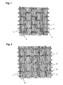
- the woven carbon fiber fabric shown in Fig. 1 is a uni-directional woven fabric.
- the woven carbon fiber fabric 1 has many carbon fiber yarns 2 arranged.
- Each of the carbon fiber yarns 2 consists of about 40,000 to about 400,000 carbon filaments 3.
- the carbon filaments 3 have filament interlacements.
- the warp threads arranged to form the woven structure of the woven fabric 1 are the carbon fiber yarns 2, and the weft threads arranged are auxiliary yarns 4.
- the auxiliary yarns 4 have a low temperature melting polymer deposited, and after the polymer is molten, solidified portions 5 are formed to bond the auxiliary yarns 4 to the carbon fiber yarns 2.
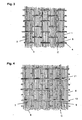
- the woven carbon fiber fabric shown in Fig. 2 is a uni-directional woven fabric.
- the woven carbon fiber fabric 6 has many arranged carbon fiber yarns 7.
- Each of the carbon fiber yarns 7 consists of about 40,000 to about 400,000 carbon filaments 8.
- the carbon filaments 8 have filament interlacements.
- the warp threads arranged to form the woven structure of the woven fabric 6 are first auxiliary yarns 9, and weft threads arranged are second auxiliary yarns 10.
- the respective carbon fiber yarns 7 are arranged in the direction of the warp threads (the first auxiliary yarns 9) across the weft threads (the second auxiliary yarns 10).
- the second auxiliary yarns 10 have a low temperature melting polymer deposited, and after the polymer is molten, solidified portions 11 are formed to bond the second auxiliary yarns 10 to the carbon fiber yarns 7.
- the carbon fiber yarns 7 are arranged like a sheet, and the second auxiliary yarns 10 are located alternately on the right and wrong sides of the sheet.
- the first auxiliary yarns located between the respective carbon fiber yarns 7 and the second auxiliary yarns 10 form the woven structure.
- the respective carbon fiber yarns 7 do not have the bends (crimps) formed by a woven structure.
- the CFRP formed by using this woven fabric is not stressed locally intensively and has a high strength.
- the auxiliary yarns woven to form the woven fabric do not substantially bear the loads in the molding, and are used to keep the form of the woven fabric till the molding is produced, i.e., used to form the woven structure. Therefore, the fineness of each of the auxiliary yarns is required to be in a range of about 100 to about 2,000 deniers, and it is preferable that they are thinner than the mainly used carbon fiber yarns.
- each of the auxiliary yarns is in a range of about 100 to about 500 deniers, being very thinner than that of the carbon fiber yarns and that the density of the auxiliary yarns of the weft threads is in a range of about 0.5 to about 8 picks/cm, since the woven fabric becomes bulky while the auxiliary yarns of the weft threads constrain the carbon fiber yarns less.
- the dry heat shrinkage at 150°C of the auxiliary yarns is less than about 0.1% for securing the dimensional stability of the woven fabric and for preventing the shrinkage caused by heating when the low temperature melting polymer is used for bonding at the intersections between the warp and weft threads.
- the fibers used as the auxiliary yarns can be carbon fibers, glass fibers or polyaramid fibers.
- the areal unit weight of carbon fibers is in a range of about 400 to about 2,000 g/m 2 , since the number of the woven fabric sheets laminated for obtaining the desired properties of CFRP can be small, to lessen the trouble of fibrous material lamination work at the time of molding, hence saving the labor for molding.
- the clearances between the respectively adjacent carbon fiber yarns are in a range of about 0.2 to about 2 mm, since the clearances becomes the passages of the resin injected into the fibrous material enclosed in a mold and a bag film in resin transfer molding or vacuum bag molding, to shorten the resin injection time for enhancing the molding efficiency.
- Figs. 3 and 4 Uni-directional woven fabrics with clearances formed between the respectively adjacent carbon fiber yarns are shown in Figs. 3 and 4.
- Fig. 3 shows a woven fabric with clearances C formed between the respectively adjacent carbon fiber yarns 2 in the woven fabric 1 shown in Fig. 1 .
- Fig. 4 shows a woven fabric with clearances C formed between the respectively adjacent carbon fiber yarns 7 in the woven fabric 6 shown in Fig. 2 .
- a uni-directional woven fabric if the number of filaments constituting each of the carbon fiber yarns is in a range of about 40,000 to about 400,000, the yarn fineness is in a range of about 30,000 to about 70,000 deniers, and the areal unit weight of carbon fibers is in a range of about 400 to about 700 g/m 2 , then the woven carbon fiber fabric becomes bulky, and when the FRP obtained by using the woven carbon fiber fabric is molded by the hand lay-up molding method using a room temperature curable resin with a viscosity of about 2 to 7 poises, the woven carbon fiber fabric can be sufficiently impregnated with the resin by an ordinary impregnation roller.
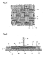
- the woven carbon fiber fabric shown in Fig. 5 is a bidirectional woven fabric.
- the woven carbon fiber fabric 12 has many carbon fiber yarns 13 and 15 arranged.
- Each of the carbon fiber yarns 13 or 15 consists of about 40,000 to about 400,000 carbon filaments 14 or 16.
- the carbon filaments 14 and 16 have filament interlacements.
- the warp threads arranged to form the woven structure of the woven fabric 12 are the carbon fiber yarns 13, and the weft threads arranged are the carbon fiber yarns 15.
- the carbon fiber yarns 15 of the weft threads have a low temperature melting polymer deposited partially on the surfaces, and after the polymer is molten, solidified portions 17 are formed, to bond the carbon fiber yarns 15 of the weft threads to the carbon fiber yarns 13 of the warp threads.
- a low temperature melting polymer is used for bonding the weft threads to the carbon fiber yarns in the above three embodiments. Since the thickness of each of the carbon fiber yarns used in the woven carbon fiber fabric of the present invention is very larger than that of the carbon fiber yarns used in the conventional woven carbon fiber fabric, the number of intersections between the warp threads and the weft threads directly contributing to the woven structure is small in the woven carbon fiber fabric of the present invention. So, when the woven fabric is cut, the carbon fiber yarns are likely to be frayed, to inconvenience the handling of the woven fabric. The bonding by the low temperature melting polymer is intended to fasten the yarns of the woven fabric and improves the handling convenience of the woven fabric.
- the working convenience is greatly improved in the resin transfer molding or vacuum bag molding in which cut sheets of a woven fabric must be laminated in a mold.
- the low temperature melting polymer is deposited on either or both of the warp threads and the weft threads in lines or dots.
- the amount of the low temperature melting polymer is less than about 6 g/m 2 since a larger amount of it inhibits resin impregnation and lowers the mechanical properties of CFRP. However, if the amount is less than about 0.5 g/m 2 , the effect of fastening the warp and weft threads at their intersections becomes weak. So, the preferable range is about 0.5 to about 6 g/m 2 .
- the low temperature melting polymer can be usually selected from polyamides, copolyamides, polyesters, copolyesters, polyvinylidene chloride, polyvinyl chloride and polyurethane.
- a copolyamide is especially preferable since it can be molten at a low temperature, is high in adhesive strength and can provide the expected thread fastening effect by a slight amount.
- the woven fabric used is the woven carbon fiber fabric of the present invention. If the fibrous material consists of a plurality of woven fabric sheets, at least one of the woven fabric sheets is the woven carbon fiber fabric of the present invention.
- Other woven fiber fabrics used with the at least one sheet of the woven carbon fiber fabric of the present invention can be woven reinforcing fiber fabrics of glass fibers or polyaramid fibers, etc.
- the matrix resins which can be used include thermosetting resins such as epoxy resins, unsaturated polyester resins, vinyl ester resins and phenol resins, and thermoplastic resins such as polyamide resins, polyester resins, ABS resins, polyethylene resin, polypropylene resin, polyvinyl chloride resin, polyether ether ketone resins and polyphenylene sulfide resin.
- thermosetting resins such as epoxy resins, unsaturated polyester resins, vinyl ester resins and phenol resins
- thermoplastic resins such as polyamide resins, polyester resins, ABS resins, polyethylene resin, polypropylene resin, polyvinyl chloride resin, polyether ether ketone resins and polyphenylene sulfide resin.
- the fiber reinforced plastic molding of the present invention uses a woven carbon fiber fabric very large in the areal unit weight of carbon fibers and yet bulky as the fibrous material. So, at the time of molding, the fibrous material can be well impregnated with the matrix resin, and the obtained molding is excellent in mechanical properties and inexpensive.
- the fiber reinforced plastic molding obtained by using the woven carbon fiber fabric of the present invention can be produced by any of various conventionally known molding methods and apparatuses.
- the woven carbon fiber fabric of the present invention which is large in the areal unit weight of carbon fibers and yet bulky is especially suitable for the resin transfer molding and the vacuum bag molding, and large moldings can be produced at a low cost by these molding methods.
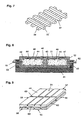
- a predetermined number of sheets of woven fabrics 22 including the woven carbon fiber fabric of the present invention are laminated. These laminated sheets of woven fabrics 22 form a fibrous material 23 of the fiber reinforced plastic molding to be produced.
- an edge breather 24 is provided, and an air suction opening 25 connected to a vacuum pump (not illustrated) is provided on the under face of the edge breather.
- the edge breather 24 is a laminate comprising many porous sheets such as woven fabrics.
- a peel ply 26 is laminated as a sheet to be peeled and removed after the matrix resin has been cured.
- a diffusion medium 27 is placed to diffuse the resin over the entire surface of the fibrous material 23.
- a bag film 28 is placed to cover them.
- the resin supply pipe 29 has a resin supply control valve 30 at an intermediate position.
- connection between the resin supply pipe 29 and the bag film 28 and the peripheral clearance between the bag film 28 and the mold 21 are sealed by sealants 31 and 32 respectively.
- the resin tank (not illustrated) contains a room temperature curable thermosetting resin (matrix resin) syrupy at room temperature mixed with a predetermined amount of a curable agent.
- the air in the space of the fibrous material 23 covered with the bag film 28 is discharged by a vacuum pump (not illustrated) through the suction opening 25 till the space reaches a reduced pressure of about 700 to about 760 Torrs. Then, the valve 30 is opened, to start the supply of the resin into the fibrous material 23.
- the resin flow resistance in the plane direction of the diffusion medium 27 is smaller than that in the normal direction of the fibrous material 23. So, the resin spreads over the entire face of the diffusion medium 27 and then permeates the fibrous material 23 in the normal direction. According to this method, since the distance for the resin to permeate the fibrous material 23 is substantially the thickness of the fibrous material 23, the impregnation of the resin into the fibrous material 23 as a whole is completed very soon.
- the vacuum pump (not illustrated) is operated at least till the impregnation of the resin into the fibrous material 23 is completed.
- valve 30 After completion of resin impregnation, the valve 30 is closed. The mold is allowed to stand at room temperature till the injected resin is cured. After the resin has been cured, the bag film 28, diffusion medium 27 and peel ply 26 are removed, and the FRP molding is taken out of the mold 21.
- the diffusion medium 27 consists of many bars 33 and 34 arranged at predetermined intervals.
- the bars 33 and the bars 34 are arranged substantially to be perpendicular to each other.
- the resin flows into the center of the diffusion medium 27 trough the resin supply pipe 29.
- the injected resin flows through the clearances between the bars 33 and 34.
- the flow of the resin causes the resin to penetrate the peel ply 26 and to diffuse substantially uniformly over the entire surface of the fibrous material 23.
- each of the bars 33 and 34 is not especially limited, but it is preferable that the thickness is in a range of about 0.2 to about 2 mm. It is preferable that clearances between the bars 33 and 34 are in a range of about 0.2 to about 2 cm.
- the bars 33 and 34 can be, for example, made of polypropylene, polyethylene, polyester or polyvinyl chloride, or can be a metallic meshed sheet.
- the meshed sheet can be a meshed film, woven fabric, knitted fabric or net, etc.
- the bars 33 and 34 can also be formed by overlaying a plurality of meshed sheets as required.
- the fiber reinforced plastic molding of the present invention as the 2nd embodiment consists of a fiber reinforced plastic with the woven carbon fiber fabric of the present invention contained in it and another molding member.
- the molding member has grooves on the side facing the fiber reinforced plastic, and the grooves are filled with the resin used to form the fiber reinforced plastic.
- the molding has a fibrous material laminated on the molding member with grooves formed as passages of a resin, and is furthermore covered entirely with a back film.
- the inside covered with the bag film is kept in vacuum (reduced pressure), and the resin is diffused through the grooves of the molding member in contact with the fibrous material.
- the fibrous material laminate is impregnated with a room temperature curable resin, the fibrous material and the molding member are integrated, to produce the molding.
- the grooves formed in the molding member allow the resin to be easily diffused, with the FRP used as a surface member or a back member, and a fiber reinforced plastic molding in which the FRP and the molding member are integrated can be simply produced.
- a mold 41 on a mold 41, molding blocks 42 and 43 with the same structure are placed.
- the molding block 42 (43) is formed by a molding member 44 (45) and a fibrous material 46 (47) surrounding it.
- the fibrous material 46 (47) is a two-layer laminate comprising a woven fabric 48 (49) positioned inside and a woven fabric 50 (51) positioned outside. At least either of the woven fabrics 48 and 50 is the woven carbon fiber fabric of the present invention. Furthermore, at least either of the woven fabrics 49 and 50 is the woven carbon fiber fabric of the present invention.
- the molding blocks 42 and 43 are covered with a bag film 52, and at the periphery of the bag film 52, the bag film 52 is connected with the mold 41 by a sealant 53, to keep the inside of the bag film 52 sealed from the outside fluid-tightly.
- FIG. 9 An example of the molding member 44 (45) is shown in Fig. 9 .
- the molding member 44 has grooves 60 in the top face 54, bottom face 55, front face 56, rear face 57, right-hand side face 58 and left-hand side face 59. These grooves 60 act as the passages of the resin when the molding is produced.
- a resin supply pipe 61 connected to a resin supply tank (not illustrated) is opened to the surface of the molding member 44 through the sealant 53 and the fibrous material 46.
- a suction pipe 62 connected to a vacuum pump (not illustrated) is opened to the surface of the molding member 45 through the sealant 53 and the fibrous material 47.
- the matrix resin flows into the space through the resin supply pipe 61 from the resin supply tank.
- the injected resin flows in the grooves small in flow resistance formed in the molding members 44 and 45, to diffuse into the molding members 44 and 45 entirely. Then, the impregnation of the resin into the fibrous materials 46 and 47 takes place.
- the supply of the resin is stopped, and the mold 41 is allowed to stand at room temperature.
- the matrix resin contained in the fibrous materials 46 and 47 and the resin filling the grooves 60 are cured, to integrate the fibrous materials 46 and 47 and the molding members 44 and 45, to produce a fiber reinforced plastic molding.
- each of the fibrous materials is formed by two layers of woven carbon fabrics, but the number of woven fabric layers laminated can be selected as required.
- Each of the fibrous materials can also contain any other woven fabric than the woven carbon fiber fabric.
- the number of molding blocks is two, but it can be selected as required.
- the fiber reinforced plastic molding of the present invention as the 2nd embodiment has the fiber reinforced plastic and the molding members strongly integrated, not only since the fiber reinforced plastic and the molding members are bonded at the interfaces between the fiber reinforced plastic and the molding members but also since the grooves of the molding members are integrated with the matrix resin.
- the sectional form of the grooves of the molding members can be rectangular, trapezoidal or semicircular, etc., and the sectional form and dimensions can be decided properly, depending on the flowability of the resin and the bonding degree between the fiber reinforced plastic and molding members. It is especially preferable that the sectional form of the grooves is like a wedge wider in the bottom of each groove than at the top of the groove, since the fiber reinforced plastic and the molding members can be bonded strongly.
- the molding members can be formed by any of various materials such as resins, metals and timber. It is preferable that the molding members are formed by an organic or inorganic foam, since the obtained molding can be light in weight.
- the organic or inorganic foam can be a foam of polyurethane, polystyrene, polyethylene, polypropylene, PVC, silicone, isocyanurate, phenol or acrylic resin, light-weight regular concrete, calcium silicate foam or calcium carbonate foam, etc.
- the compressive strength of the molding members is more than about 1.0 kgf/cm 2 . If the compressive strength is less than about 1.0 kgf/cm 2 , bag molding members may be crushed in the case of vacuum bag molding.
- the molding method described above is a vacuum bag molding method, but since a resin is diffused over the entire surface of the fibrous material using a diffusion medium as soon as the resin is injected, it is different from the conventional vacuum bag molding method. According to the molding method of the present invention, a large FRP molding can be easily produced.
- the woven carbon fiber fabric of the present invention is large in the areal unit weight of carbon fibers per sheet and yet is bulky since the carbon filaments are interlaced with each other, having clearances between the carbon filaments.
- the resin flow in the plane direction of the fibrous material is assured, and the fibrous material itself has a structure to allow easy resin flow. So, the trouble in the lamination work of the fibrous material is less and the impregnation of the resin into the fibrous material laminate can be effected perfectly. Furthermore, the resin injection time can be shortened, to remarkably improve the molding work efficiency.
- the fibrous material is not required to be formed by the woven carbon fiber fabric of the present invention alone, and at least one layer in the fibrous material is required to be the woven carbon fiber fabric of the present invention.
- the other layers in the fibrous material than the woven carbon fiber fabric sheet of the present invention can be of any ordinary woven carbon fiber fabric or can be any ordinary woven fabric, chopped strand mat or continuous strand mat, etc. formed by the other reinforcing fibers such as glass fibers or polyaramid fibers.
- he other layers in the fibrous material than the woven carbon fiber fabric sheet of the present invention may be of a multi-axially stitched cloth comprising laminated sheets each of which is formed by the reinforcing fibers each of which is arranged in parallel wherein the sheets are arranged the fibers in different directions such as 0° direction (longitudinal direction of the fibrous material), 90° direction (transverse direction of the fibrous material) or ⁇ 45° direction (oblique direction of the fibrous material) and sewn with a stitching yarn such as glass fibers, polyester fibers or polyamide fibers, etc.
- the FRP molding produced by using it can have such a structure that the molding is reinforced in the main necessary direction by the unidirectional woven carbon fiber fabric and reinforced in the other directions by the multi-axially stitched cloth.
- the fibrous material has a large fiber content by volume, since the carbon fiber yarns and other reinforcing fiber yarns are not interlaced with each other and are arranged straight without being bent.
- the FRP molding produced by using the fibrous material is excellent in mechanical properties. Since the carbon fibers and other reinforcing fibers are not clamped by the interlacements between yarns, the fibrous material can be sufficiently impregnated with a resin in the vacuum bag molding, and the impregnation rate is also high.
- the resins which can be used in the fiber reinforced plastic molding of the present invention include room temperature curable resins liquid at room temperature such as epoxy resins, unsaturated polyester resins, vinyl ester resins and phenol resins. It is preferable that the viscosity of the resin is low, i.e., in a range from about 0.5 to about 10 poises in view of resin impregnability and impregnation rate. A more preferable range is about 0.5 to about 5 poises. Especially a vinyl ester resin can be preferably used for such reasons that it is excellent in moldability since it can be low in viscosity and as large as about 3.5 to about 12% in elongation, and that the molding obtained has high strength and excellent impact resistance.
- the peel ply is a sheet peeled and removed from the FRP after the resin has been cured, and must allow the passage of the resin during molding work.
- It can be, for example, a woven polyamide fiber fabric, woven polyester fiber fabric or woven glass fiber fabric. Since the woven polyamide fiber fabric and the woven polyester fiber fabric are inexpensive, they can be preferably used. However, to prevent that the oil and sizing agent used when the woven fabric is produced go into the resin of the FRP, it is preferable to scour the woven fabric before use, and furthermore, to prevent the shrinkage of the room temperature curable resin by curing heat, it is preferable to heat-set the woven fabric before use.
- the edge breather must be able to allow the passage of air and resin.
- the edge breather can be, for example, a woven polyamide fiber fabric, woven polyester fiber fabric, woven glass fiber fabric or a mat of polyamide fibers or polyester fibers.
- the bag film must be air-tight. It can be, for example, a polyamide film, polyester film or PVC film.
- the hook drop value expresses the degree of interlacements between the respective carbon filaments constituting the carbon fiber yarns in the woven carbon fiber fabric of the present invention.
- the hook drop value expressing the degree of interlacements is hereinafter expressed as FD (15) .
- the FD (15) is measured as follows.
- the deposited sizing agent is removed without disturbing the fiber arrangement.
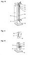
- a measuring instrument 71 shown in Fig. 10 consists of a base 72, a graduated column 73 fixed on it vertically, a top clamp 74 installed at the top, a bottom clamp 75 installed below, a hook 76, a weight 77 and a cotton yarn 78 connecting the hook 76 with the weight 77.
- the distance LA between the bottom end of the top clamp 74 and the top end of the bottom claim 75 (clamp distance) is 950 mm.
- the detail of the hook 76, the weight 77 and the cotton yarn 78 connecting the hook 76 with the weight 77 is shown in Fig. 11 .
- the hook 76 is formed by a metallic wire with a diameter of 1 mm, and has a hook portion bent with a radius of curvature of 5 mm in the central axis of the wire at its top, and a weight hanging portion connected with the cotton yarn 78 at its bottom. To the weight hanging portion, the weight 77 is attached by the cotton yarn 78.
- the distance LB between the top of the hook 76 and the upper face of the weight 77, with the hook 76, cotton yarn 78 and weight 77 connected straight, is 30 mm.
- the weights of the hook 76 and the cotton yarn 78 are made as light as possible, and the total weight obtained by adding the weight of the weight 77 to these weights is 15 g.
- the hook 76 is manually hooked in the yarn 79 at the center in the transverse direction of the yarn 79 fixed by the top clamp 74 and the bottom clamp 75, with the top of the hook 76 positioned at 50 mm below the under face of the top clamp 74.
- the distance between the under face of the top clamp 74 and the initial top position of the hook 76 when the hook 76 is hooked in the yarn 79 is indicated by symbol LC in Fig. 10 .
- the weight 77 hooked in the yarn 79 If the weight 77 hooked in the yarn 79 is released from hand, it starts dropping. With the drop of the weight 77, the hook 76 moves downward. However, the dropping of the hook 76 stops before long, being affected by the filament interlacements existing between the respective filaments of the yarn 79. So, the distance (cm) between the initial top position of the hook 76 and the terminating top position is measured.
- This measurement is repeated 10 times for one sample yarn taken out of one piece of the woven fabric. Since three pieces of the woven fabric are used, 30 measured values in total can be obtained. The FD (15) is obtained as the average value of these measured values.
- the metallic hook 76 drops to the position of the bottom clamp 75, and in this case, the dropping distance is regarded to be 900 mm.
- the dropping distance is regarded to be 900 mm.
- the yarns 79 are sampled after the woven fabric is allowed to stand in an environment of 25°C and 60% relative humidity for 24 hours.
- the FD (15) is measured in an atmosphere of 25°C and 60% relative humidity.
- the FD (15) is affected by it, depending on the amount and state of the deposition. So, the sizing agent is perfectly removed before measurement.
- the sizing agent can be removed by heat-treating the yarn in 700°C nitrogen atmosphere for 1 hour.
- the FD (15) is affected by it. So, the resin is perfectly removed before measurement. For example, if the deposited resin is a vinyl ester resin, it can be removed by heat-treating the yarn in 700°C nitrogen atmosphere for 5 hours.
- a uni-directional woven fabric shown in Fig. 1 Prepared was a woven carbon fiber fabric 1 (A) of plain weave with 52,000-denier carbon fiber tows 2 respectively comprising 70,000 carbon filaments 3 as warp threads and 608-denier glass fiber auxiliary yarns 4 as weft threads (hence carbon fiber yarns are arranged in uni direction only) at a warp thread density of 0.87 ends/cm at a weft thread density of 2 picks/cm, with an areal carbon fiber unit weight of 500 g/m 2 and with the thread intersections fastened.
- A woven carbon fiber fabric 1 (A) of plain weave with 52,000-denier carbon fiber tows 2 respectively comprising 70,000 carbon filaments 3 as warp threads and 608-denier glass fiber auxiliary yarns 4 as weft threads (hence carbon fiber yarns are arranged in uni direction only) at a warp thread density of 0.87 ends/cm at a weft thread density of 2 picks/cm, with an
- the woven fabric 1 For fastening the thread intersections, when the woven fabric 1 was produced, 50-denier low temperature melting copolyamide yarns paralleled with the auxiliary yarns of the weft threads were molten by a far infrared heater attached on the weaving machine, after inserting the weft, to bond the carbon fiber yarns 2 with the auxiliary yarns 4.
- the obtained woven fabric 1 (A) was bulky since the carbon filaments constituting the carbon fiber yarns 2 were interlaced with each other, and the thickness of the woven fabric was 1.1 mm.
- the FD (15) value of the carbon fiber yarns 2 taken out of the woven fabric 1 (A) was 6.3 cm.
- the clearances between the respectively adjacent carbon fiber yarns 2 were 1.2 mm.
- the woven fabric 1 (A) was fastened at the thread intersections, the weave texture was not disturbed though the density of the woven fabric was coarse, and the woven fabric remained stable in form.
- the weaving speed expressed by the weight of the carbon fibers woven per hour reached 15 kg/1 hr since the carbon fiber tows were thick. The woven fabric could be produced at a very low cost.
- Woven carbon fiber fabric B is a Woven carbon fiber fabric
- the carbon filaments constituting the carbon fiber yarns were arranged substantially in parallel and were little interlaced with each other. So, the filaments were densely bundled, and the thickness of the woven fabric was 0.8 mm.
- the FD (15) value of the carbon fiber yarns taken out of the woven fabric was 42.0 cm.
- the woven fabric was coarsely dense and was not fastened at the thread intersections. So, the weave texture was simply disturbed, and the woven fabric was unstable in form.
- the weaving speed was 15 kg/1 hr as in the production of the woven carbon fiber fabric A, since the carbon fiber yarns of the warp threads were thick.
- Woven carbon fiber fabric C Woven carbon fiber fabric C:
- a uni-directional woven fabric for comparison was a woven carbon fiber fabric C of plain weave with 3,600-denier multi-filament yarns respectively comprising 6,000 carbon filaments as warp threads and 202.5-denier glass fiber auxiliary yarns as weft threads (hence carbon fiber yarns were arranged in uni direction only) at a warp thread density of 6.3 picks/cm at a weft thread density of 2 ends/cm, with an areal carbon fiber unit weight of 252 g/m 2 and with the thread intersections fastened.
- the fastening of thread intersections was effected as described for the woven fabric A.
- the areal carbon fiber unit weight of the woven fabric C was almost half that of the woven fabric A.
- the FD (15) value of the carbon fiber yarns taken out of the woven fabric was 15.7 cm.
- the weaving speed was as low as 7.5 kg/1 hr, being almost half that of the woven fabric A.
- Table 1 Woven carbon fiber fabric Woven fabric A Woven fabric B Woven fabric C Woven fabric of present invention Comparative woven fabric Comparative woven fabric Weaving speed (kg/1 hr) 15 15 7.5 Whether or not thread intersections were fastened Yes No Yes
- the above woven carbon fiber fabrics A, B and C were used to produce fiber reinforced plastic moldings according to the hand lay-up method (molding method I) in Example 1 and Comparative Example 1., and according to the vacuum bag molding method (molding method II) using the diffusion medium 27 (see Figs. 6 and 7 ) of the present invention, in Examples 2 and 3 and Comparative Examples 2 to 4.
- the first sheet of the woven fabric A was coated with a room temperature curable vinyl ester resin with a viscosity of 3 poises uniformly and deaerated by a fluted deaeration roller, to prepare a 1st layer of the woven fabric, and the second sheet of the woven fabric A was laminated on the 1st layer of the woven fabric as the 2nd layer of the woven fabric with the warp carbon fiber yarns kept in the same direction as that of the 1st layer of the woven fabric, and coated and impregnated with the same resin as used for the 1st layer.
- the laminate was allowed to stand at 20°C, to cure the resin, for preparing a molding A.
- a molding B was prepared as described for preparing the molding A, except that the woven carbon fiber fabric B was used.
- Example 1 The respective properties of the molding A obtained in Example 1 and the molding B obtained in Comparative Example 1 are shown in Table 2.
- Each tensile property of a molding is expressed as a transfer ratio to show the property of the molding exhibited compared to that of the carbon fibers used, since the woven fabrics A and B were different in the properties of the carbon fibers used to make the respective woven fabrics.
- Table 2 Molding method I Example 1 Comparative Example 1 Molding A Molding B Woven carbon fiber fabric Woven fabric A Woven fabric B Thickness molding board (mm) 2.2 1.8 Resin impregnated state Almost perfect Partially unimpregnated Transfer ratio of tensile strength (%) 92 72 Transfer ratio of tensile modulus (%) 100 90
- the molding A produced by using the woven carbon fiber fabric A of the present invention was sufficiently impregnated with the resin, since the woven fabric was bulky, though somewhat thick, with the carbon fibers interlaced with each other in the carbon fiber yarns, even though the carbon fiber yarns were thick. Therefore, the transfer ratio of tensile strength was 92% and the transfer ratio of tensile modulus of elasticity was 100%, to sufficiently manifest the tensile properties of the carbon fibers used to obtain the woven fabric.
- the molding B obtained by using the woven carbon fiber fabric B was not sufficiently impregnated with the resin in the molding board, leaving especially the central portions of the carbon fiber yarns unimpregnated, since the carbon fibers were not interlaced with each other in the carbon fiber yarns, hence densely packed. Therefore, the transfer ratio of tensile strength was 72% and the transfer ratio of tensile modulus of elasticity was 90%, not manifesting the tensile properties of the carbon fibers sufficiently.
- the 1st sheet of the woven carbon fiber fabric A was laminated, and three sheets of the chopped strand mat were laminated one by one on it with the edges of the woven fabric A kept flush with the edges of the mat. Furthermore, on them, the 2nd sheet of the woven carbon fiber fabric A was laminated, to form a fibrous material 23 comprising 5 layers in total of the woven fabric and the mat.
- a woven polyamide filament fabric was placed as the peel ply 26.
- two meshed polyethylene sheets respectively with a thickness of 1.0 mm, with a mesh size of 2.6 mm x 2.6 mm and with a mesh opening rate (the ratio of the area of the meshes, with the entire area as 100) of 62% were placed as a diffusion medium 27 to cover the upper surface of the fibrous material 23.
- a woven glass fiber fabric almost as thick as the fibrous material 23 was installed as the edge breather 24.
- a suction opening 25 connected to a vacuum pump was installed on the under face of the edge breather 24.
- a resin supply pipe 29 was installed, and the clearance around the installed portion was sealed by a sealant 31.
- the inside covered with the bag film 28 was kept at a reduced pressure of 755 Torrs, and the valve 30 installed on the resin supply pipe 29 was opened, to inject a room temperature curable vinyl ester resin with a viscosity of 3 poises into the fibrous material 23.
- the resin was sufficiently cured, and the peel ply 26 was removed.
- the diffusion medium 27 and the bag film 28 were also removed, and a fiber reinforced plastic molding was taken out of the mold 21, as molding C.
- Molding D was produced as described for producing the molding C, except that the woven carbon fabric B was used instead of the woven carbon fabric A.
- a molding E was produced as described for producing the molding C, except that two sheets of the woven carbon fiber fabric C were used instead of one sheet of the woven carbon fiber fabric A.
- the properties of the three moldings A, B and C are shown in Table 3.
- the lamination time in Table 3 is the time taken for cutting sheets of predetermined dimensions from a woven fabric roll and a mat roll and laminating them on a mold as a predetermined fibrous material. Since the lamination work was carried out by two workers, the time is the total time of two persons.
- Table 3 Molding method II Example 2 Comparative Example 2 Comparative Example 3 Molding C Molding D Molding E Woven carbon fiber fabric Woven fabric A Woven fabric B Woven fabric C Composition of fibrous material Woven fabric (sheets) 2 2 4 Mat (sheets) 3 3 3 3 Lamination time (min) 40 47 60 Resin injection time (min) 23 50 21 Resin impregnated state Perfect Partially unimpregnated Perfect
- the yarns were not frayed by cutting, since the woven fabric A had been fastened at the thread intersections. Furthermore, since the woven fabric A was large in the areal unit weight of fibers, the woven fabric as a whole was hard to some extent. So, even if the length was 5 m, it did not happen in the lamination work that the woven fabric was bent, or that the central portion of the woven fabric contacted the mold or the previously laminated sheet, and lamination could be completed substantially without any disturbance in the arranged fibers. The time taken for cutting 5 sheets of the woven fabric and the mat and laminating them was 40 minutes in total of two persons.
- the resin could be immediately diffused over the entire surface area of 1 m x 5 m, and could permeate the fibrous material in the normal direction.
- the time taken for resin injection was 23 minutes. After curing of the resin, the molded board was cut, to observe the section, and it was confirmed that the resin impregnation was perfect.
- the yarns were frayed by cutting since the woven fabric B had the thread intersections not fastened. Furthermore, since the woven fabric was large in the areal unit weight of fibers and soft, the woven fabric as long as 5 m was bent due to its own weight when it was going to be laminated, and it took a long time to laminate the respective sheets without allowing that the central portion of the woven fabric contacted the mold or the previously laminated sheet lest the arranged fibers should be disturbed. The time taken for cutting five sheets of the woven fabric and the mat and laminating them was 47 minutes in total of two persons.
- the overlying sheet of the woven fabric was poor in resin impregnability and penetrability, and before the resin impregnation was sufficiently achieved, the room temperature curable resin was cured in about 50 minutes.
- the underlying sheet of the woven fabric B in contact with the mold had portions not accessed by the resin, i.e., unimpregnated portions at portions far away from the injection port of the resin supply pipe. So, no satisfactory molded board could be obtained.
- the woven fabric C was small in the areal unit weight of carbon fibers per sheet, it was good in resin impregnability, and the time taken for resin injection was 21 minutes, being almost the same as in the case of the molding C.
- the first sheet of the woven carbon fiber fabric A was laminated, and on it, three sheets of the chopped strand mat were laminated one by one with the edges of the woven fabric A flush with the edges of the mat. Furthermore, on them, the second sheet of the woven carbon fiber fabric A was laminated, to form a fibrous material 23 comprising five sheets in total of the woven fabric and the mat.
- a woven polyamide filament fabric was placed as the peel ply 26.
- two meshed polyethylene sheets respectively with a thickness of 1.0 mm, with a mesh size of 2.6 mm x 2.6 mm with a mesh opening rate (the rate of the area of meshes, with the total area as 100) of 62% were placed as a diffusion medium 27 to cover the upper surface of the fibrous material 23.
- a woven glass fiber fabric almost as thick as the fibrous material 23 was installed as the edge breather 24.
- a suction opening 25 connected to a vacuum pump was installed on the under face of the edge breather 24.
- the inside covered with the bag film 28 was kept at a reduced pressure of 755 Torrs, and the valve 30 installed on the resin supply pipe 29 was opened, to inject a room temperature curable vinyl ester resin with a viscosity of 3 poises into the fibrous material 23.
- the resin was immediately diffused over the entire surface of the fibrous material 23 by the diffusion medium 27.
- the resin flowed through the clearances between the respective filaments of the carbon fiber yarns and through the clearances between the respective carbon fiber yarns in the upper sheet of the woven carbon fiber fabric A into the sheets of the chopped strand mat in the normal direction of the fibrous material 23.
- the time taken for the resin impregnation into the fibrous material 23 was 16 minutes. After the resin had been cured, the molding was taken out of the mold 21 and cut to observe the section. It was confirmed that the resin had been perfectly impregnated.
- the clearances between the respective adjacent carbon fiber yarns in the obtained woven fabric were substantially 0 mm.
- a fiber reinforced plastic molding was produced as described in Example 3, except that the woven carbon fiber fabric D was used instead of the woven carbon fiber fabric A.
- the resin was immediately diffused over the entire surface of the fibrous material 23, thanks to the action of the diffusion medium 27.
- the woven fabric B positioned at the top of the fibrous material 23 had a large areal carbon fiber unit weight and substantially without little clearances between the carbon fiber yarns, the resin permeation toward the sheets of the chopped strand mat positioned below was not smooth. So, the resin did not flow sufficiently to the sheet of the woven fabric B positioned at the bottom, and 50 minutes after start of resin injection, the resin began to be gelled. The molding work failed.
Landscapes
- Engineering & Computer Science (AREA)
- Textile Engineering (AREA)
- Chemical & Material Sciences (AREA)
- Composite Materials (AREA)
- Mechanical Engineering (AREA)
- Inorganic Chemistry (AREA)
- Reinforced Plastic Materials (AREA)
- Woven Fabrics (AREA)
- Moulding By Coating Moulds (AREA)
- Laminated Bodies (AREA)
- Casting Or Compression Moulding Of Plastics Or The Like (AREA)
Applications Claiming Priority (2)
| Application Number | Priority Date | Filing Date | Title |
|---|---|---|---|
| JP209213/97 | 1997-08-04 | ||
| JP20921397 | 1997-08-04 |
Publications (2)
| Publication Number | Publication Date |
|---|---|
| EP0909845A1 EP0909845A1 (en) | 1999-04-21 |
| EP0909845B1 true EP0909845B1 (en) | 2010-01-06 |
Family
ID=16569233
Family Applications (1)
| Application Number | Title | Priority Date | Filing Date |
|---|---|---|---|
| EP98114188A Expired - Lifetime EP0909845B1 (en) | 1997-08-04 | 1998-07-29 | A woven carbon fiber fabric, a fiber reinforced plastic molding obtained by using the woven fabric, and a production method of the molding |
Country Status (10)
| Country | Link |
|---|---|
| EP (1) | EP0909845B1 (enExample) |
| JP (1) | JP3991439B2 (enExample) |
| KR (1) | KR100570229B1 (enExample) |
| CN (1) | CN100430543C (enExample) |
| AU (1) | AU743038B2 (enExample) |
| CA (1) | CA2244361C (enExample) |
| DE (1) | DE69841431D1 (enExample) |
| ES (1) | ES2339909T3 (enExample) |
| HU (1) | HU227725B1 (enExample) |
| TW (1) | TW475953B (enExample) |
Cited By (2)
| Publication number | Priority date | Publication date | Assignee | Title |
|---|---|---|---|---|
| US10017870B2 (en) | 2012-08-22 | 2018-07-10 | Infineon Technologies Ag | Method for fabricating a heat sink, and heat sink |
| US11453199B2 (en) | 2017-11-01 | 2022-09-27 | Nitto Denko Corporation | Laminate and reinforcing sheet |
Families Citing this family (35)
| Publication number | Priority date | Publication date | Assignee | Title |
|---|---|---|---|---|
| JP2000238140A (ja) * | 1999-02-17 | 2000-09-05 | Toray Ind Inc | Frp筒状体およびその製造方法 |
| US20030186038A1 (en) * | 1999-11-18 | 2003-10-02 | Ashton Larry J. | Multi orientation composite material impregnated with non-liquid resin |
| BR0102038A (pt) * | 2000-02-01 | 2004-08-24 | Wellstream Inc | Conjunto de tiras compostas e método para a sua formação |
| US20020160252A1 (en) * | 2001-02-28 | 2002-10-31 | Mitsubishi Chemical Corporation | Conductive carbonaceous-fiber sheet and solid polymer electrolyte fuel cell |
| JP4839523B2 (ja) * | 2001-04-17 | 2011-12-21 | 東レ株式会社 | 繊維強化樹脂の製造方法 |
| EP2311618A3 (en) | 2002-07-18 | 2013-08-14 | Mitsubishi Rayon Co., Ltd. | Prepreg and method for production thereof |
| EP1550766A4 (en) * | 2002-09-25 | 2009-07-22 | Mitsubishi Chem Corp | TEXTILE STRUCTURE OF FIBER carbonaceous, WRAP OF TEXTILE FABRIC FROM carbon-FIBER, GAS DIFFUSION LAYER MATERIAL FOR SOLID POLYMER FUEL CELL, PROCESS FOR PRODUCING A sheet of carbon-FIBER AND METHOD FOR PRODUCING A SOLID POLYMER FUEL CELL |
| JP4542588B2 (ja) * | 2002-10-09 | 2010-09-15 | 東レ株式会社 | Rtm成形方法 |
| AU2003262050B2 (en) * | 2002-11-14 | 2009-07-02 | Toray Industries, Inc. | Reinforcing fiber substrate, composite material and method for producing the same |
| JP4370797B2 (ja) * | 2003-04-11 | 2009-11-25 | 東レ株式会社 | Frp製薄板の製造方法 |
| US7168272B2 (en) | 2003-09-30 | 2007-01-30 | Owens Corning Fiberglas Technology, Inc. | Crimp-free infusible reinforcement fabric |
| KR101135406B1 (ko) * | 2003-09-30 | 2012-04-17 | 오웬스 코닝 | 무권축 함침 가능 보강 직물과 이로부터 만들어진 복합보강재 |
| JP4603297B2 (ja) * | 2004-06-07 | 2010-12-22 | 旭化成せんい株式会社 | ポリヘキサメチレンアジパミド繊維 |
| EP1685947B1 (en) | 2005-02-01 | 2011-04-13 | Honda Motor Co., Ltd. | Method for the manufacture of FRP composites |
| US7857013B2 (en) * | 2006-04-28 | 2010-12-28 | Toray Industries, Inc. | Method for producing carbon fiber woven fabric |
| JP5136876B2 (ja) * | 2006-11-28 | 2013-02-06 | 東レ株式会社 | 強化繊維積層体およびその製造方法 |
| WO2008121984A1 (en) * | 2007-03-29 | 2008-10-09 | Acme United Corporation | Cutting instrument |
| CN101532253B (zh) * | 2008-03-12 | 2012-09-05 | 比亚迪股份有限公司 | 碳纤维复合材料制品及其制造方法 |
| TWI472656B (zh) * | 2008-04-11 | 2015-02-11 | Toray Industries | 碳纖維前驅物纖維及碳纖維與其製法 |
| KR100957100B1 (ko) * | 2008-05-30 | 2010-05-13 | 현대자동차주식회사 | 차량용 범퍼 백빔 성형방법 |
| WO2011081486A2 (ko) | 2009-12-30 | 2011-07-07 | 코오롱인더스트리 주식회사 | 에어백 쿠션 및 이를 포함하는 에어백 시스템 |
| US8940222B2 (en) * | 2011-11-03 | 2015-01-27 | The Boeing Company | High flow edge breather and method |
| JP5726713B2 (ja) * | 2011-11-21 | 2015-06-03 | 津田駒工業株式会社 | 炭素繊維基材及び炭素繊維強化プラスチック |
| TWI474919B (zh) * | 2012-03-28 | 2015-03-01 | Blade Structure and Fabrication Method of Composite Material Wind Turbine | |
| US8985270B2 (en) | 2013-03-11 | 2015-03-24 | Molded Acoustical Products Of Easton, Inc. | Clean burn muffler packing with stitched fiberglass envelope |
| CN103352297A (zh) * | 2013-07-02 | 2013-10-16 | 山东万泰创业投资有限公司 | 一种薄荷纤维莫代尔棉炭黑牛仔面料及其生产方法 |
| US10597804B2 (en) | 2015-08-24 | 2020-03-24 | Uchino Co., Ltd. | Multiple woven gauze fabric |
| CN107400959A (zh) * | 2017-06-23 | 2017-11-28 | 太仓大唐化纤厂 | 一种竖孔发泡纤维布 |
| JP2019093685A (ja) * | 2017-11-28 | 2019-06-20 | 東洋製罐グループホールディングス株式会社 | 繊維強化積層体及びその製造方法 |
| CN111705469A (zh) * | 2020-06-22 | 2020-09-25 | 科纺勒特种纺织品(太仓)有限公司 | 一种碳纤维织物均匀处理方法及设备 |
| CN113136653B (zh) * | 2021-03-12 | 2023-01-03 | 山东莱蔚特复合材料有限责任公司 | 一种玻璃纤维表面毡糊制装置 |
| CN113831687B (zh) * | 2021-09-26 | 2023-07-21 | 西安工程大学 | 一种压电纱线增强树脂基复合材料的制备方法 |
| GB202210346D0 (en) | 2022-07-14 | 2022-08-31 | Rolls Royce Plc | Woven structure, method and apparatus for a flanged composite component |
| WO2025051626A1 (de) | 2023-09-06 | 2025-03-13 | Teijin Carbon Europe Gmbh | Automatisches ablegeverfahren zur herstellung eines vorformlings mittels gewebeband |
| CN118650940B (zh) * | 2024-08-20 | 2025-03-07 | 泉州市富合新材料科技有限公司 | 一种具备石墨烯导电膜的面料及制备方法 |
Family Cites Families (7)
| Publication number | Priority date | Publication date | Assignee | Title |
|---|---|---|---|---|
| DE2162174A1 (de) * | 1971-12-15 | 1973-06-28 | Willy Muehlau | Verfahren zur herstellung von verbundelementen mit deckschichten aus haertbaren kunststoffen durch anbringung zusaetzlicher fliesskanaele |
| US4714642A (en) | 1983-08-30 | 1987-12-22 | Basf Aktiengesellschaft | Carbon fiber multifilamentary tow which is particularly suited for weaving and/or resin impregnation |
| JPS63152637A (ja) * | 1986-12-16 | 1988-06-25 | Toray Ind Inc | 樹脂の補強用プリフオ−ム材 |
| US4902215A (en) | 1988-06-08 | 1990-02-20 | Seemann Iii William H | Plastic transfer molding techniques for the production of fiber reinforced plastic structures |
| JPH0771804B2 (ja) * | 1990-10-12 | 1995-08-02 | 株式会社神戸製鋼所 | 炭素繊維プリプレグ及び炭素繊維強化樹脂 |
| JP3094835B2 (ja) * | 1994-03-08 | 2000-10-03 | 東レ株式会社 | 補強織物とその製造方法および製造装置 |
| DE69507956T2 (de) * | 1994-07-21 | 1999-09-09 | Akzo Nobel N.V. | Zyklische keton peroxyde zubereitungen |
-
1998
- 1998-04-16 JP JP10645898A patent/JP3991439B2/ja not_active Expired - Lifetime
- 1998-07-29 TW TW087112430A patent/TW475953B/zh not_active IP Right Cessation
- 1998-07-29 ES ES98114188T patent/ES2339909T3/es not_active Expired - Lifetime
- 1998-07-29 EP EP98114188A patent/EP0909845B1/en not_active Expired - Lifetime
- 1998-07-29 AU AU78562/98A patent/AU743038B2/en not_active Expired
- 1998-07-29 DE DE69841431T patent/DE69841431D1/de not_active Expired - Lifetime
- 1998-07-30 CA CA002244361A patent/CA2244361C/en not_active Expired - Lifetime
- 1998-08-03 CN CNB981178553A patent/CN100430543C/zh not_active Expired - Lifetime
- 1998-08-03 HU HU9801783A patent/HU227725B1/hu unknown
- 1998-08-04 KR KR1019980031678A patent/KR100570229B1/ko not_active Expired - Lifetime
Cited By (2)
| Publication number | Priority date | Publication date | Assignee | Title |
|---|---|---|---|---|
| US10017870B2 (en) | 2012-08-22 | 2018-07-10 | Infineon Technologies Ag | Method for fabricating a heat sink, and heat sink |
| US11453199B2 (en) | 2017-11-01 | 2022-09-27 | Nitto Denko Corporation | Laminate and reinforcing sheet |
Also Published As
| Publication number | Publication date |
|---|---|
| KR19990023333A (ko) | 1999-03-25 |
| HU227725B1 (en) | 2012-01-30 |
| HUP9801783A2 (hu) | 2000-04-28 |
| CA2244361A1 (en) | 1999-02-04 |
| DE69841431D1 (de) | 2010-02-25 |
| JP3991439B2 (ja) | 2007-10-17 |
| HUP9801783A3 (en) | 2000-06-28 |
| CN1210913A (zh) | 1999-03-17 |
| ES2339909T3 (es) | 2010-05-26 |
| JPH11107105A (ja) | 1999-04-20 |
| TW475953B (en) | 2002-02-11 |
| CA2244361C (en) | 2006-10-17 |
| KR100570229B1 (ko) | 2006-07-21 |
| AU743038B2 (en) | 2002-01-17 |
| AU7856298A (en) | 1999-02-11 |
| CN100430543C (zh) | 2008-11-05 |
| EP0909845A1 (en) | 1999-04-21 |
| HU9801783D0 (en) | 1998-09-28 |
Similar Documents
| Publication | Publication Date | Title |
|---|---|---|
| EP0909845B1 (en) | A woven carbon fiber fabric, a fiber reinforced plastic molding obtained by using the woven fabric, and a production method of the molding | |
| AU760808B2 (en) | Composite reinforcing fiber base material, preform and production method for fiber reinforced plastic | |
| US5484642A (en) | Textile material useful for producing composite laminated articles by injection molding | |
| US5021281A (en) | Laminated material reinforced by a multi-dimensional textile structure and method for producing the same | |
| US20080295950A1 (en) | Open Grid Fabric Resin Infusion Media and Reinforcing Composite Lamina | |
| JPWO2000056539A1 (ja) | 複合強化繊維基材、プリフォームおよび繊維強化プラスチックの製造方法 | |
| EP0144939A2 (en) | Base Cloth for Reinforcement | |
| EP2006064A2 (en) | Process for producing fiber-reinforced resin | |
| JPH0422933B2 (enExample) | ||
| JPH0197233A (ja) | 多層織物をベースとした建築部材およびその製造方法 | |
| EP1175998A1 (en) | Preform for composite material and composite material | |
| US5143569A (en) | Method for manufacturing a three dimensional laminate from double pile fabrics | |
| JP2001062932A (ja) | 繊維強化樹脂構造体およびその製造方法 | |
| EP0426158A2 (en) | Unidirectionally fiber reinforced thermoplastic composites and method of manufacture | |
| JP3991440B2 (ja) | 繊維強化プラスチックおよび繊維強化プラスチックの成形方法 | |
| CN113573875B (zh) | 缝合的多轴增强件 | |
| JPH0135101B2 (enExample) | ||
| JP4984973B2 (ja) | 繊維強化樹脂の製造方法 | |
| BRPI0414826B1 (pt) | pano de reforço infusível desprovido de pregas e processo para produção de um pano | |
| JPH07308927A (ja) | 繊維強化樹脂発泡成形体及びその製造方法 | |
| EP1935637A1 (en) | Moldable construction incorporating bonding interface | |
| JPH0362546B2 (enExample) | ||
| JPH1044182A (ja) | 繊維強化樹脂複合体の製造方法 |
Legal Events
| Date | Code | Title | Description |
|---|---|---|---|
| PUAI | Public reference made under article 153(3) epc to a published international application that has entered the european phase |
Free format text: ORIGINAL CODE: 0009012 |
|
| AK | Designated contracting states |
Kind code of ref document: A1 Designated state(s): DE ES FR GB IT NL |
|
| AX | Request for extension of the european patent |
Free format text: AL;LT;LV;MK;RO;SI |
|
| 17P | Request for examination filed |
Effective date: 19990812 |
|
| AKX | Designation fees paid |
Free format text: DE ES FR GB IT NL |
|
| 17Q | First examination report despatched |
Effective date: 20080812 |
|
| GRAP | Despatch of communication of intention to grant a patent |
Free format text: ORIGINAL CODE: EPIDOSNIGR1 |
|
| GRAS | Grant fee paid |
Free format text: ORIGINAL CODE: EPIDOSNIGR3 |
|
| GRAA | (expected) grant |
Free format text: ORIGINAL CODE: 0009210 |
|
| AK | Designated contracting states |
Kind code of ref document: B1 Designated state(s): DE ES FR GB IT NL |
|
| REG | Reference to a national code |
Ref country code: GB Ref legal event code: FG4D |
|
| REF | Corresponds to: |
Ref document number: 69841431 Country of ref document: DE Date of ref document: 20100225 Kind code of ref document: P |
|
| REG | Reference to a national code |
Ref country code: NL Ref legal event code: T3 |
|
| REG | Reference to a national code |
Ref country code: ES Ref legal event code: FG2A Ref document number: 2339909 Country of ref document: ES Kind code of ref document: T3 |
|
| PLBE | No opposition filed within time limit |
Free format text: ORIGINAL CODE: 0009261 |
|
| STAA | Information on the status of an ep patent application or granted ep patent |
Free format text: STATUS: NO OPPOSITION FILED WITHIN TIME LIMIT |
|
| 26N | No opposition filed |
Effective date: 20101007 |
|
| REG | Reference to a national code |
Ref country code: FR Ref legal event code: PLFP Year of fee payment: 19 |
|
| REG | Reference to a national code |
Ref country code: FR Ref legal event code: PLFP Year of fee payment: 20 |
|
| PGFP | Annual fee paid to national office [announced via postgrant information from national office to epo] |
Ref country code: FR Payment date: 20170613 Year of fee payment: 20 |
|
| PGFP | Annual fee paid to national office [announced via postgrant information from national office to epo] |
Ref country code: NL Payment date: 20170614 Year of fee payment: 20 |
|
| PGFP | Annual fee paid to national office [announced via postgrant information from national office to epo] |
Ref country code: ES Payment date: 20170804 Year of fee payment: 20 Ref country code: DE Payment date: 20170725 Year of fee payment: 20 Ref country code: GB Payment date: 20170726 Year of fee payment: 20 Ref country code: IT Payment date: 20170720 Year of fee payment: 20 |
|
| REG | Reference to a national code |
Ref country code: DE Ref legal event code: R071 Ref document number: 69841431 Country of ref document: DE |
|
| REG | Reference to a national code |
Ref country code: NL Ref legal event code: MK Effective date: 20180728 |
|
| REG | Reference to a national code |
Ref country code: GB Ref legal event code: PE20 Expiry date: 20180728 |
|
| PG25 | Lapsed in a contracting state [announced via postgrant information from national office to epo] |
Ref country code: GB Free format text: LAPSE BECAUSE OF EXPIRATION OF PROTECTION Effective date: 20180728 |
|
| REG | Reference to a national code |
Ref country code: ES Ref legal event code: FD2A Effective date: 20220103 |
|
| PG25 | Lapsed in a contracting state [announced via postgrant information from national office to epo] |
Ref country code: ES Free format text: LAPSE BECAUSE OF EXPIRATION OF PROTECTION Effective date: 20180730 |