EP0909607B9 - Dispositif de serrage pour le soudage de tôles - Google Patents
Dispositif de serrage pour le soudage de tôles Download PDFInfo
- Publication number
- EP0909607B9 EP0909607B9 EP98830514A EP98830514A EP0909607B9 EP 0909607 B9 EP0909607 B9 EP 0909607B9 EP 98830514 A EP98830514 A EP 98830514A EP 98830514 A EP98830514 A EP 98830514A EP 0909607 B9 EP0909607 B9 EP 0909607B9
- Authority
- EP
- European Patent Office
- Prior art keywords
- plate
- sheet metal
- supporting
- screws
- wall
- Prior art date
- Legal status (The legal status is an assumption and is not a legal conclusion. Google has not performed a legal analysis and makes no representation as to the accuracy of the status listed.)
- Expired - Lifetime
Links
- 238000003466 welding Methods 0.000 title claims abstract description 13
- 229910052751 metal Inorganic materials 0.000 title claims abstract description 12
- 239000002184 metal Substances 0.000 claims abstract description 8
- 238000010276 construction Methods 0.000 description 1
- 239000012530 fluid Substances 0.000 description 1
Images

Classifications
-
- B—PERFORMING OPERATIONS; TRANSPORTING
- B25—HAND TOOLS; PORTABLE POWER-DRIVEN TOOLS; MANIPULATORS
- B25B—TOOLS OR BENCH DEVICES NOT OTHERWISE PROVIDED FOR, FOR FASTENING, CONNECTING, DISENGAGING OR HOLDING
- B25B5/00—Clamps
- B25B5/006—Supporting devices for clamps
-
- B—PERFORMING OPERATIONS; TRANSPORTING
- B23—MACHINE TOOLS; METAL-WORKING NOT OTHERWISE PROVIDED FOR
- B23K—SOLDERING OR UNSOLDERING; WELDING; CLADDING OR PLATING BY SOLDERING OR WELDING; CUTTING BY APPLYING HEAT LOCALLY, e.g. FLAME CUTTING; WORKING BY LASER BEAM
- B23K37/00—Auxiliary devices or processes, not specially adapted for a procedure covered by only one of the other main groups of this subclass
- B23K37/04—Auxiliary devices or processes, not specially adapted for a procedure covered by only one of the other main groups of this subclass for holding or positioning work
- B23K37/0426—Fixtures for other work
- B23K37/0435—Clamps
-
- B—PERFORMING OPERATIONS; TRANSPORTING
- B23—MACHINE TOOLS; METAL-WORKING NOT OTHERWISE PROVIDED FOR
- B23K—SOLDERING OR UNSOLDERING; WELDING; CLADDING OR PLATING BY SOLDERING OR WELDING; CUTTING BY APPLYING HEAT LOCALLY, e.g. FLAME CUTTING; WORKING BY LASER BEAM
- B23K37/00—Auxiliary devices or processes, not specially adapted for a procedure covered by only one of the other main groups of this subclass
- B23K37/04—Auxiliary devices or processes, not specially adapted for a procedure covered by only one of the other main groups of this subclass for holding or positioning work
- B23K37/0408—Auxiliary devices or processes, not specially adapted for a procedure covered by only one of the other main groups of this subclass for holding or positioning work for planar work
-
- B—PERFORMING OPERATIONS; TRANSPORTING
- B23—MACHINE TOOLS; METAL-WORKING NOT OTHERWISE PROVIDED FOR
- B23K—SOLDERING OR UNSOLDERING; WELDING; CLADDING OR PLATING BY SOLDERING OR WELDING; CUTTING BY APPLYING HEAT LOCALLY, e.g. FLAME CUTTING; WORKING BY LASER BEAM
- B23K2101/00—Articles made by soldering, welding or cutting
- B23K2101/18—Sheet panels
Definitions
- the present invention relates to devices for locating and locking in position components of pressed sheet metal which are to be subjected to a welding operation.
- the invention relates to clamp devices of the type indicated in the preamble of claim 1.
- a clamp device of this type is known from DE-U-296 22 739.
- clamp devices of the above indicated type have been known and used for a long time, for instance in assembling operations by means of welding of units constituted by elements of pressed sheet metal, such as motor-vehicle bodies or subassemblies thereof.
- FIG. 1 shows one embodiment of a clamp device according to the prior art.
- a structure 1 of pressed sheet metal is constituted by two sheet metal elements 2, 3 which must be welded by means of electric spot welding at two juxtaposed flanges 2a, 3a thereof.
- Elements 2, 3 are clamped in the proper welding position by means of a clamp device 4 comprising a fixed supporting element 5 and a movable clamp element 6 adapted to be closed over supporting element 5 to clamp the two juxtaposed flanges 2a, 3a in the proper welding position, so that these flanges can then be welded to each other by applying electric welding spots at areas not covered by the two elements 5, 6 of the clamp device 4.
- the fixed supporting element 5 is connected by screws to a fixed supporting structure 7 by means of an angled member 8.
- Registering plates 9,10 are interposed between the angled member 8 and the fixed structure 7 and the supporting element 5, respectively.
- the movable clamp element 6 is pivotally supported around an axis 11 by a supporting body 12 which on its turn is secured by screws to the structure 7 with the interposition of a registering plate 13.
- a registering plate 14 is also interposed between the movable clamp element 6 and a lever 15 which is directly pivotally mounted around axis 11 on the body 12 and whose rotation is driven by a fluid cylinder 16 which is also carried by body 12.
- the use of registering plates 9, 10, 13, 14 is due to the need of assuring that elements 5, 6 of the clamp device 4 are in the required proper position relative to the position of the structure to be welded 1.
- the structure 1 is brought to a welding station and located in position therein by means independent from the clamp device 4. Therefore, the position of the structure 1 to be welded is to be considered as predetermined and is then necessary that elements 5, 6 are at a proper position relative thereto.
- the structure 1 reaches the welding station, it is arranged on the supporting element 5, in the condition shown in figure 1, but, obviously, with the movable clamp element 6 in an upwardly rotated condition with respect to that shown in figure 1.
- the cylinder 16 may then be activated to drive a closing movement of the movable clamp element 6 over the two juxtaposed flanges 2a, 3a of the two components of sheet metal 2, 3, so as to obtain precise location and clamping of these flanges between the two elements 5, 6.
- the object of the present invention is that of overcoming this drawback.
- the invention provides a clamp device of the type indicated at the beginning of the present description, characterized in that it further includes the features of claim 1.
- the fixed supporting structure preferably comprises an angled supporting member which is in contact with two orthogonal surfaces of the first supporting element to provide a reference of the proper assembling position of the supporting element relative to the fixed supporting structure, for the case the supporting element has to be disassembled temporarily.
- two plates are interposed by which the assembling position of the supporting element can be adjusted.
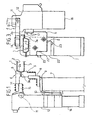
- the main difference of the device according to the invention with respect to the known device shown in figure 1 lies in that in the case of the device according to the invention the body 12 carrying the movable clamp element 6 is not secured directly to the fixed supporting structure 7, but rather is carried by the latter by means of the first supporting element 5. As a matter of fact, the body 12 is secured by screws 17 to a bracket 18 which on its turn is directly secured to the fixed supporting element 5. There are no other direct connection between body 12 and the fixed structure 7. Therefore, contrary to the known device, in which the elements 5, 6 are carried independently by the fixed structure 7, the relative position of these elements is univocally determined and defined once for all and therefore has not to be registered.
- the fixed supporting element 5 having an upper edge 5a shaped to define a reference for the structure to be clamped, is constituted by a vertical plate secured to a vertical wall 7a of the fixed supporting structure 7 by means of a pair of screws 19 which engage holes of corresponding diameter formed in wall 7 as and holes of enlarged diameter formed in plate 5.
- angled supporting member 20 against which orthogonal edges 5b, 5c of plate 5 are supported, with the interposition of plates 21, 22.
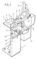
- the angled member 20 is not yet mounted on the fixed structure 7.
- the plate 5 is adjusted in the proper position and than fixed by means of screws 19 to the structure 7.
- the angle member 20 is brought in contact with the two edges 5b, 5c of the plate 5, with the interposition of plates 21, 22. Screws 23 lock the angled member 20 on the plate 5 and hold the plates 21, 22.
- the seats of screws 23 on the angled member 20 are provided to allow an orthogonal movement of the plate in case of a variation of plates 21, 22.
- the angled member 20, once assembled on plate 5 with plates 21, 22 is there welded or otherwise secured to structure 7. In this manner, if plate 5 has to be disassembled, it can be immediately mounted again and positioned in the properposition, due to the reference provided by the angled member 20.
- the structure to be welded is clamped between the fixed element 5 and the movable element 6, which is closed over the fixed element 5.
- the closed and opened positions of element 6 are shown respectively in figures 3, 4 and also in figure 2 respectively with undotted lines and dotted lines.
- the device according to the invention has the advantage that it never requires an operation for registering the relative position of the two elements 5, 6, since the body 12 carrying the element 6 is directly mounted on the element 5.
- Figure 5 shows a variant in which the angled member 20 has been replaced by two separate beams 20a, 20b welded to the structure 7, whereas the two orthogonal screws 23 have been replaced by a single screw 230 arranged at 45° at the corner between edges 5b, 5c of element 5.
- the device according to the invention avoids the time consuming and troublesome registering operations which are instead necessary with the known devices.
Landscapes
- Engineering & Computer Science (AREA)
- Mechanical Engineering (AREA)
- Physics & Mathematics (AREA)
- Optics & Photonics (AREA)
- Butt Welding And Welding Of Specific Article (AREA)
- Resistance Welding (AREA)
- Arc Welding In General (AREA)
- Connection Of Plates (AREA)
- Jigs For Machine Tools (AREA)
- Clamps And Clips (AREA)
Claims (3)
- Dispositif permettant de positionner et de verrouiller en position des composants en tôle emboutie (2, 3) devant être soumis à une opération de soudage, le dispositif comprenant :- un premier élément (5) destiné à soutenir les composants en tôle (2, 3) dans la position de soudage voulue, ledit premier élément (5) étant relié rigidement à une structure de support fixe (7), et- un deuxième élément (6) servant à serrer les composants en tôle devant être soudés (2, 3), ledit deuxième élément (6) étant monté rotatif sur un corps (12) porté par ladite structure de support fixe (7) de façon à pouvoir tourner entre une position inactive, qui est écartée du premier élément de support (5), et une position active, dans laquelle il est adjacent au premier élément de support (5) et coopère avec celui-ci si bien que lesdits composants en tôle (2, 3) sont serrés dans la position de soudage voulue entre les premier et deuxième éléments (5, 6),- un cylindre (16) porté par ledit corps (12) servant à faire tourner ledit deuxième élément de serrage mobile (6),où ledit corps (12) portant l'élément de serrage mobile (6) est soutenu par ladite structure de support fixe (16) par l'intermédiaire dudit premier élément de support (5), auquel ledit corps (12) portant l'élément de serrage mobile (6) est relié directement par des vis (17), et
où ledit premier élément de support comprend une plaque (5) reliée à une paroi (7a) de la structure de support fixe (7) par des vis (19) vissées dans des trous de ladite plaque possédant des diamètres agrandis,
caractérisé en ce que :ladite plaque (5) est une plaque verticale disposée de façon que son plan soit orthogonal par rapport à l'axe de rotation (11) dudit deuxième élément (6) et possède un bord supérieur (5a) ayant, quand on regarde dans la direction de l'axe de rotation (11) du deuxième élément (6), un profil conformé comportant une cavité équipée d'un fond et de deux côtés permettant un contact conformé avec un composant en tôle (3) conformé de façon correspondante de la structure à serrer, de manière à ainsi définir une référence pour la position de la structure à serrer, suivant une direction horizontale qui est perpendiculaire audit axe de rotation (11),ladite paroi (7a) de la structure de support fixe (7) à laquelle ladite plaque verticale (5) est fixée est une paroi verticale qui est également disposée de façon que son plan soit perpendiculaire à l'axe de rotation (11) dudit deuxième élément (6),lesdites vis (19) qui relient ladite plaque (5) à la paroi (7a) de la structure de support fixe (7) sont disposées parallèlement à l'axe de rotation (11) dudit deuxième élément (6),de sorte que ladite plaque verticale (5) peut être ajustée en position par dessus ladite paroi verticale (7a) de la structure de support fixe (7) simultanément suivant deux directions mutuellement perpendiculaires, dans un plan qui est perpendiculaire à l'axe de rotation (11) dudit deuxième élément (6) et perpendiculairement auxdites vis (19) qui sont vissées dans les trous de diamètres agrandis, lors du desserrage de ces vis (19). - Dispositif de serrage selon la revendication 1, caractérisé en ce que ladite paroi (7a) est dotée d'un élément de support (20) formant un angle, qui est en contact avec les deux bords perpendiculaires (5a, 5c) de la plaque (5) de façon à produire une référence pour la position d'assemblage correcte de la plaque (5).
- Dispositif de serrage selon la revendication 2, caractérisé en ce que des plaques d'ajustement (21, 22) s'interposent entre ledit élément (20) formant un angle et ladite plaque (5).
Applications Claiming Priority (2)
| Application Number | Priority Date | Filing Date | Title |
|---|---|---|---|
| ITTO970906 | 1997-10-14 | ||
| IT97TO000906A IT1295715B1 (it) | 1997-10-14 | 1997-10-14 | Dispositivo di bloccaggio utilizzabile nella saldatura di elementi di lamiera metallica. |
Publications (4)
| Publication Number | Publication Date |
|---|---|
| EP0909607A1 EP0909607A1 (fr) | 1999-04-21 |
| EP0909607B1 EP0909607B1 (fr) | 2001-10-10 |
| EP0909607B2 EP0909607B2 (fr) | 2006-12-20 |
| EP0909607B9 true EP0909607B9 (fr) | 2007-05-23 |
Family
ID=11416069
Family Applications (1)
| Application Number | Title | Priority Date | Filing Date |
|---|---|---|---|
| EP98830514A Expired - Lifetime EP0909607B9 (fr) | 1997-10-14 | 1998-08-28 | Dispositif de serrage pour le soudage de tôles |
Country Status (7)
| Country | Link |
|---|---|
| US (1) | US6129345A (fr) |
| EP (1) | EP0909607B9 (fr) |
| KR (1) | KR100320607B1 (fr) |
| AT (1) | ATE206650T1 (fr) |
| BR (1) | BR9804492A (fr) |
| DE (1) | DE69801971T3 (fr) |
| IT (1) | IT1295715B1 (fr) |
Families Citing this family (18)
| Publication number | Priority date | Publication date | Assignee | Title |
|---|---|---|---|---|
| IT1302835B1 (it) * | 1998-10-23 | 2000-10-10 | Fata Automation | Stazione di assemblaggio e metodo di gestione per essa |
| DE10205541C1 (de) * | 2002-02-08 | 2003-05-15 | Daimler Chrysler Ag | Spanneinrichtung zum Klemmen von Werkstücken aus Blech |
| US6752368B2 (en) | 2002-10-30 | 2004-06-22 | Alcoa Inc. | Clamping device and method for grasping a workpiece |
| US7815176B2 (en) | 2003-09-11 | 2010-10-19 | Phd, Inc. | Lock mechanism for pin clamp assembly |
| US7516948B2 (en) | 2004-04-02 | 2009-04-14 | Phd, Inc. | Pin clamp accessories |
| US7182326B2 (en) | 2004-04-02 | 2007-02-27 | Phd, Inc. | Pin clamp |
| US7448607B2 (en) | 2004-12-15 | 2008-11-11 | Phd, Inc. | Pin clamp assembly |
| EP1967318A1 (fr) * | 2007-03-06 | 2008-09-10 | COMAU S.p.A. | Dispositif de localisation et de verrouillage d'éléments d'une plaque métallique pressée avec un corps auxiliaire ayant des passages pour fixer de la tuyauterie |
| WO2008157698A2 (fr) | 2007-06-19 | 2008-12-24 | Phd, Inc. | Ensemble pince broche |
| WO2009155261A1 (fr) | 2008-06-18 | 2009-12-23 | Phd, Inc. | Pince à broche à enlèvement |
| FR2958570B1 (fr) * | 2010-04-12 | 2012-04-27 | Peugeot Citroen Automobiles Sa | Procede pour regler la position des appuis destines a maintenir deux toles destinees a etre assemblees par soudure laser et installation de ferrage pour la mise en oeuvre de ce procede |
| DE102011016274A1 (de) * | 2011-04-06 | 2012-10-11 | Invenio Gmbh Engineering Services | Abstimmblock zum Halten oder Auflegen eines Werkstücks |
| USD666976S1 (en) * | 2011-08-10 | 2012-09-11 | Continental Industries, Inc. | Cathodic protection mold magnet assembly |
| CN103862408B (zh) * | 2012-12-18 | 2015-12-09 | 北汽福田汽车股份有限公司 | 手持式夹具 |
| CN103331550B (zh) * | 2013-07-09 | 2014-10-15 | 南通金亿达门业有限公司 | 门面成型夹具 |
| GB2523374A (en) * | 2014-02-24 | 2015-08-26 | Clockwork Engineering Ltd | Vice apparatus |
| US9906093B2 (en) | 2014-10-31 | 2018-02-27 | Delaware Capital Formation, Inc. | Universal housing mount |
| CN112536565A (zh) * | 2020-11-30 | 2021-03-23 | 中国第一汽车股份有限公司 | 一种侧围外板尾部回弹控制结构 |
Family Cites Families (11)
| Publication number | Priority date | Publication date | Assignee | Title |
|---|---|---|---|---|
| US4352003A (en) * | 1979-09-17 | 1982-09-28 | Ductmate Industries, Inc. | Method for positioning and securing components of a workpiece |
| US4691905A (en) † | 1985-04-18 | 1987-09-08 | Nissan Motor Co., Ltd. | Machine for holding workpiece |
| US4669227A (en) * | 1985-06-24 | 1987-06-02 | Treppner Bernaht C | Angle plate apparatus with precisely adjustable workpiece holder |
| US4687190A (en) * | 1986-05-28 | 1987-08-18 | Yang Tai Her | Bench vise |
| DE8805178U1 (de) † | 1988-04-19 | 1989-08-24 | De-Sta-Co Metallerzeugnisse Gmbh, 6000 Frankfurt | Bauelementensatz zur Ausbildung eines Befestigungsträgers für Spannvorrichtungen |
| US5415383A (en) † | 1992-06-01 | 1995-05-16 | Ausilio; John S. | Clamp arm with slip plane positioning |
| JP3172587B2 (ja) * | 1992-07-01 | 2001-06-04 | 株式会社東京洗染機械製作所 | 可燃性溶剤使用のドライクリーニング装置におけるすゝぎ洗い工程制御方法 |
| US5216930A (en) * | 1992-07-31 | 1993-06-08 | Litton Industrial Automation Systems, Inc. | Power work arm |
| DE29509049U1 (de) † | 1995-06-01 | 1995-10-26 | Thyssen Industrie Ag, 45128 Essen | Vorrichtung zum Einspannen von Bauteilen, insbesondere von Blechen im Zuge einer Schweiß- oder Montagestraße |
| DE29622739U1 (de) † | 1996-04-29 | 1997-05-28 | Emil Bucher GmbH & Co. Modell- und Maschinenbau, 73054 Eislingen | Spanneinheit für Spannvorrichtungen, die Werkstücke mit komplizierter Geometrie halten |
| DE59708597D1 (de) † | 1996-04-29 | 2002-12-05 | Emil Bucher Gmbh & Co Modell U | Spanneinheit für ein Spann-Baukastensystem, das Werkstücke mit komplizierter Geometrie haltert, sowie Verfahren zur Justierung einer Basislänge |
-
1997
- 1997-10-14 IT IT97TO000906A patent/IT1295715B1/it active IP Right Grant
-
1998
- 1998-08-28 EP EP98830514A patent/EP0909607B9/fr not_active Expired - Lifetime
- 1998-08-28 DE DE69801971T patent/DE69801971T3/de not_active Expired - Lifetime
- 1998-08-28 AT AT98830514T patent/ATE206650T1/de not_active IP Right Cessation
- 1998-09-01 US US09/145,346 patent/US6129345A/en not_active Expired - Fee Related
- 1998-09-28 KR KR1019980040190A patent/KR100320607B1/ko not_active IP Right Cessation
- 1998-10-13 BR BR9804492-3A patent/BR9804492A/pt not_active IP Right Cessation
Also Published As
| Publication number | Publication date |
|---|---|
| IT1295715B1 (it) | 1999-05-27 |
| ITTO970906A1 (it) | 1999-04-14 |
| EP0909607A1 (fr) | 1999-04-21 |
| KR19990036688A (ko) | 1999-05-25 |
| BR9804492A (pt) | 1999-11-09 |
| DE69801971T3 (de) | 2007-04-26 |
| ATE206650T1 (de) | 2001-10-15 |
| DE69801971T2 (de) | 2002-04-04 |
| EP0909607B1 (fr) | 2001-10-10 |
| US6129345A (en) | 2000-10-10 |
| DE69801971D1 (de) | 2001-11-15 |
| EP0909607B2 (fr) | 2006-12-20 |
| KR100320607B1 (ko) | 2002-04-22 |
Similar Documents
| Publication | Publication Date | Title |
|---|---|---|
| EP0909607B9 (fr) | Dispositif de serrage pour le soudage de tôles | |
| US8661956B2 (en) | Rear mounted miter saw fence | |
| JP2609050B2 (ja) | 印刷機の版胴に版板を見当正しく取付けるための装置 | |
| US5293908A (en) | Wedge clamp for adjustably affixing a support bracket to a weaving machine | |
| US6050560A (en) | Clamping apparatus for holding a motor vehicle window pane | |
| GB2201363A (en) | Mounting of a machine on a stand | |
| US4596187A (en) | Ink metering device for a printing press | |
| GB2306629A (en) | Adjustable vehicle steering column assembly | |
| JPH06234206A (ja) | 印刷機の印刷ユニットにおけるローラのためのローラ軸受 | |
| ES2245626T3 (es) | Dispositivo para apretar componentes. | |
| DK1630333T3 (en) | Hinge with angle adjustment | |
| EP0215512A2 (fr) | Dispositif de serrage de châssis | |
| JPH09325124A (ja) | X線を利用したインゴットの結晶軸方位調整方法及び装置 | |
| US5504630A (en) | Beam steering apparatus | |
| JPH03159744A (ja) | 版板を平行に締め付ける装置 | |
| JPH0345279B2 (fr) | ||
| US5048580A (en) | Workpiece guide for portable power router | |
| EP0343200A1 (fr) | Appareil a redresser les carrosseries | |
| US20140311964A1 (en) | Adjustable vacuum pan assemblies for belt filters | |
| US5274211A (en) | Beam bender support unit | |
| JPH087978Y2 (ja) | シーム溶接機の被溶接物誘導装置 | |
| JPH06114658A (ja) | 加工機の取付位置調整方法と装置 | |
| KR950002926Y1 (ko) | 고속절단기의 절단각도 조절장치 | |
| JP2863464B2 (ja) | 角度調整機構付切断ト−チ | |
| EP1034904A2 (fr) | Dérouleuse et barre de pression pour un tel dispositif |
Legal Events
| Date | Code | Title | Description |
|---|---|---|---|
| PUAI | Public reference made under article 153(3) epc to a published international application that has entered the european phase |
Free format text: ORIGINAL CODE: 0009012 |
|
| AK | Designated contracting states |
Kind code of ref document: A1 Designated state(s): AT DE FR GB |
|
| AX | Request for extension of the european patent |
Free format text: AL;LT;LV;MK;RO;SI |
|
| 17P | Request for examination filed |
Effective date: 19990624 |
|
| AKX | Designation fees paid |
Free format text: AT DE FR GB |
|
| 17Q | First examination report despatched |
Effective date: 20000828 |
|
| GRAG | Despatch of communication of intention to grant |
Free format text: ORIGINAL CODE: EPIDOS AGRA |
|
| GRAG | Despatch of communication of intention to grant |
Free format text: ORIGINAL CODE: EPIDOS AGRA |
|
| GRAH | Despatch of communication of intention to grant a patent |
Free format text: ORIGINAL CODE: EPIDOS IGRA |
|
| GRAH | Despatch of communication of intention to grant a patent |
Free format text: ORIGINAL CODE: EPIDOS IGRA |
|
| RAP1 | Party data changed (applicant data changed or rights of an application transferred) |
Owner name: COMAU SYSTEMS S.P.A. |
|
| GRAA | (expected) grant |
Free format text: ORIGINAL CODE: 0009210 |
|
| AK | Designated contracting states |
Kind code of ref document: B1 Designated state(s): AT DE FR GB |
|
| REF | Corresponds to: |
Ref document number: 206650 Country of ref document: AT Date of ref document: 20011015 Kind code of ref document: T |
|
| REF | Corresponds to: |
Ref document number: 69801971 Country of ref document: DE Date of ref document: 20011115 |
|
| REG | Reference to a national code |
Ref country code: GB Ref legal event code: IF02 |
|
| ET | Fr: translation filed | ||
| PLBQ | Unpublished change to opponent data |
Free format text: ORIGINAL CODE: EPIDOS OPPO |
|
| PLBI | Opposition filed |
Free format text: ORIGINAL CODE: 0009260 |
|
| PLBF | Reply of patent proprietor to notice(s) of opposition |
Free format text: ORIGINAL CODE: EPIDOS OBSO |
|
| 26 | Opposition filed |
Opponent name: EMIL BUCHER GMBH & CO. MODELL- UND MASCHINENBAU Effective date: 20020710 Opponent name: KUKA SCHWEISSANLAGEN GMBH Effective date: 20020710 Opponent name: BAYERISCHE MOTOREN WERKE AKTIENGESELLSCHAFT Effective date: 20020709 Opponent name: DAIMLERCHRYSLER AG Effective date: 20020704 |
|
| PLBF | Reply of patent proprietor to notice(s) of opposition |
Free format text: ORIGINAL CODE: EPIDOS OBSO |
|
| PLBF | Reply of patent proprietor to notice(s) of opposition |
Free format text: ORIGINAL CODE: EPIDOS OBSO |
|
| PLBF | Reply of patent proprietor to notice(s) of opposition |
Free format text: ORIGINAL CODE: EPIDOS OBSO |
|
| RDAF | Communication despatched that patent is revoked |
Free format text: ORIGINAL CODE: EPIDOSNREV1 |
|
| APBP | Date of receipt of notice of appeal recorded |
Free format text: ORIGINAL CODE: EPIDOSNNOA2O |
|
| APBQ | Date of receipt of statement of grounds of appeal recorded |
Free format text: ORIGINAL CODE: EPIDOSNNOA3O |
|
| APAA | Appeal reference recorded |
Free format text: ORIGINAL CODE: EPIDOS REFN |
|
| APAH | Appeal reference modified |
Free format text: ORIGINAL CODE: EPIDOSCREFNO |
|
| RAP2 | Party data changed (patent owner data changed or rights of a patent transferred) |
Owner name: COMAU S.P.A. |
|
| APBU | Appeal procedure closed |
Free format text: ORIGINAL CODE: EPIDOSNNOA9O |
|
| PUAH | Patent maintained in amended form |
Free format text: ORIGINAL CODE: 0009272 |
|
| STAA | Information on the status of an ep patent application or granted ep patent |
Free format text: STATUS: PATENT MAINTAINED AS AMENDED |
|
| 27A | Patent maintained in amended form |
Effective date: 20061220 |
|
| AK | Designated contracting states |
Kind code of ref document: B2 Designated state(s): AT DE FR GB |
|
| ET3 | Fr: translation filed ** decision concerning opposition | ||
| PGFP | Annual fee paid to national office [announced via postgrant information from national office to epo] |
Ref country code: AT Payment date: 20080814 Year of fee payment: 11 |
|
| PG25 | Lapsed in a contracting state [announced via postgrant information from national office to epo] |
Ref country code: AT Free format text: LAPSE BECAUSE OF NON-PAYMENT OF DUE FEES Effective date: 20090828 |
|
| PGFP | Annual fee paid to national office [announced via postgrant information from national office to epo] |
Ref country code: FR Payment date: 20100824 Year of fee payment: 13 Ref country code: DE Payment date: 20100825 Year of fee payment: 13 |
|
| PGFP | Annual fee paid to national office [announced via postgrant information from national office to epo] |
Ref country code: GB Payment date: 20100825 Year of fee payment: 13 |
|
| GBPC | Gb: european patent ceased through non-payment of renewal fee |
Effective date: 20110828 |
|
| REG | Reference to a national code |
Ref country code: FR Ref legal event code: ST Effective date: 20120430 |
|
| REG | Reference to a national code |
Ref country code: DE Ref legal event code: R119 Ref document number: 69801971 Country of ref document: DE Effective date: 20120301 |
|
| PG25 | Lapsed in a contracting state [announced via postgrant information from national office to epo] |
Ref country code: GB Free format text: LAPSE BECAUSE OF NON-PAYMENT OF DUE FEES Effective date: 20110828 Ref country code: FR Free format text: LAPSE BECAUSE OF NON-PAYMENT OF DUE FEES Effective date: 20110831 |
|
| PG25 | Lapsed in a contracting state [announced via postgrant information from national office to epo] |
Ref country code: DE Free format text: LAPSE BECAUSE OF NON-PAYMENT OF DUE FEES Effective date: 20120301 |