EP0909372B1 - Handbetätigter Winkelgeber mit radialer Magnetrastierung - Google Patents
Handbetätigter Winkelgeber mit radialer Magnetrastierung Download PDFInfo
- Publication number
- EP0909372B1 EP0909372B1 EP97928180A EP97928180A EP0909372B1 EP 0909372 B1 EP0909372 B1 EP 0909372B1 EP 97928180 A EP97928180 A EP 97928180A EP 97928180 A EP97928180 A EP 97928180A EP 0909372 B1 EP0909372 B1 EP 0909372B1
- Authority
- EP
- European Patent Office
- Prior art keywords
- permanent magnet
- angle sensor
- toothed
- disc
- sensor according
- Prior art date
- Legal status (The legal status is an assumption and is not a legal conclusion. Google has not performed a legal analysis and makes no representation as to the accuracy of the status listed.)
- Expired - Lifetime
Links
- 230000004907 flux Effects 0.000 claims abstract description 6
- 230000004913 activation Effects 0.000 claims 2
- 239000004020 conductor Substances 0.000 claims 1
- 230000008878 coupling Effects 0.000 abstract 2
- 238000010168 coupling process Methods 0.000 abstract 2
- 238000005859 coupling reaction Methods 0.000 abstract 2
- 230000002787 reinforcement Effects 0.000 description 5
- 238000009434 installation Methods 0.000 description 2
- 238000004026 adhesive bonding Methods 0.000 description 1
- 230000004888 barrier function Effects 0.000 description 1
- 230000015572 biosynthetic process Effects 0.000 description 1
- 238000010276 construction Methods 0.000 description 1
- 238000011156 evaluation Methods 0.000 description 1
- 230000001771 impaired effect Effects 0.000 description 1
- 238000004519 manufacturing process Methods 0.000 description 1
- 238000005259 measurement Methods 0.000 description 1
- 210000002105 tongue Anatomy 0.000 description 1
Images

Classifications
-
- G—PHYSICS
- G01—MEASURING; TESTING
- G01D—MEASURING NOT SPECIALLY ADAPTED FOR A SPECIFIC VARIABLE; ARRANGEMENTS FOR MEASURING TWO OR MORE VARIABLES NOT COVERED IN A SINGLE OTHER SUBCLASS; TARIFF METERING APPARATUS; MEASURING OR TESTING NOT OTHERWISE PROVIDED FOR
- G01D5/00—Mechanical means for transferring the output of a sensing member; Means for converting the output of a sensing member to another variable where the form or nature of the sensing member does not constrain the means for converting; Transducers not specially adapted for a specific variable
- G01D5/12—Mechanical means for transferring the output of a sensing member; Means for converting the output of a sensing member to another variable where the form or nature of the sensing member does not constrain the means for converting; Transducers not specially adapted for a specific variable using electric or magnetic means
- G01D5/244—Mechanical means for transferring the output of a sensing member; Means for converting the output of a sensing member to another variable where the form or nature of the sensing member does not constrain the means for converting; Transducers not specially adapted for a specific variable using electric or magnetic means influencing characteristics of pulses or pulse trains; generating pulses or pulse trains
- G01D5/245—Mechanical means for transferring the output of a sensing member; Means for converting the output of a sensing member to another variable where the form or nature of the sensing member does not constrain the means for converting; Transducers not specially adapted for a specific variable using electric or magnetic means influencing characteristics of pulses or pulse trains; generating pulses or pulse trains using a variable number of pulses in a train
- G01D5/2451—Incremental encoders
-
- G—PHYSICS
- G05—CONTROLLING; REGULATING
- G05G—CONTROL DEVICES OR SYSTEMS INSOFAR AS CHARACTERISED BY MECHANICAL FEATURES ONLY
- G05G5/00—Means for preventing, limiting or returning the movements of parts of a control mechanism, e.g. locking controlling member
- G05G5/06—Means for preventing, limiting or returning the movements of parts of a control mechanism, e.g. locking controlling member for holding members in one or a limited number of definite positions only
-
- H—ELECTRICITY
- H01—ELECTRIC ELEMENTS
- H01H—ELECTRIC SWITCHES; RELAYS; SELECTORS; EMERGENCY PROTECTIVE DEVICES
- H01H5/00—Snap-action arrangements, i.e. in which during a single opening operation or a single closing operation energy is first stored and then released to produce or assist the contact movement
- H01H5/02—Energy stored by the attraction or repulsion of magnetic parts
-
- G—PHYSICS
- G05—CONTROLLING; REGULATING
- G05G—CONTROL DEVICES OR SYSTEMS INSOFAR AS CHARACTERISED BY MECHANICAL FEATURES ONLY
- G05G1/00—Controlling members, e.g. knobs or handles; Assemblies or arrangements thereof; Indicating position of controlling members
- G05G1/08—Controlling members for hand actuation by rotary movement, e.g. hand wheels
-
- H—ELECTRICITY
- H01—ELECTRIC ELEMENTS
- H01H—ELECTRIC SWITCHES; RELAYS; SELECTORS; EMERGENCY PROTECTIVE DEVICES
- H01H3/00—Mechanisms for operating contacts
- H01H3/32—Driving mechanisms, i.e. for transmitting driving force to the contacts
- H01H3/50—Driving mechanisms, i.e. for transmitting driving force to the contacts with indexing or locating means, e.g. indexing by ball and spring
- H01H2003/506—Driving mechanisms, i.e. for transmitting driving force to the contacts with indexing or locating means, e.g. indexing by ball and spring making use of permanent magnets
-
- Y—GENERAL TAGGING OF NEW TECHNOLOGICAL DEVELOPMENTS; GENERAL TAGGING OF CROSS-SECTIONAL TECHNOLOGIES SPANNING OVER SEVERAL SECTIONS OF THE IPC; TECHNICAL SUBJECTS COVERED BY FORMER USPC CROSS-REFERENCE ART COLLECTIONS [XRACs] AND DIGESTS
- Y10—TECHNICAL SUBJECTS COVERED BY FORMER USPC
- Y10S—TECHNICAL SUBJECTS COVERED BY FORMER USPC CROSS-REFERENCE ART COLLECTIONS [XRACs] AND DIGESTS
- Y10S33/00—Geometrical instruments
- Y10S33/01—Magnetic
Definitions
- the invention relates to a manually operated angle encoder with the features the preamble of claim 1.
- a known angle encoder of this type (DE 43 11 496 C2) is the encoder element a disc, the outer edge of which is formed by tongues, the are bent so that they are part of their length in one to the axis of rotation of the encoder element are concentric cylinder surface. Concentric to this cylinder surface and at a smaller radial distance from it in the circumferential direction alternating north and south poles are one the second part of the locking mechanism associated magnet provided.
- the invention is therefore based on the object of a manually operated angle encoder to create that builds smaller with the same division and is also realistic permits large installation tolerances without being impaired in its function.
- the axial arrangement of the north-south poles enables miniaturization, especially in the radial direction.
- the diameter of the angle encoder regardless of minimum distances between different poles.
- Both sides of the permanent magnet are particularly well suited for miniaturization arranged toothed disks and disks corresponding to them, are connected to each other for example by a tube.
- the exist Toothed lock washers, the washers and their connecting element made of one material, that conducts the magnetic flux well. Varies due to the contour of the teeth the air gap between toothed washers and washers, the magnetic Flow and thus the attraction of the teeth of the toothed washers and washers on largest is when the teeth face each other directly.
- Both poles can each be connected to a toothed washer, the corresponding discs are arranged at a radial distance. But it is it is also possible that only one of the two poles is connected to a toothed disk is and only a corresponding disc is provided at a radial distance. A toothless disk is then at an axial distance from the other pole arranged, the disc corresponding to the toothed disc over a Connection element is in a magnetically conductive connection.
- the toothless Washer can be a single component or with the connecting element be made in one piece in the manner of a pot.
- the number of teeth one hundred enables particularly good handling of the Angle encoder for quick and precise setting or input, for example of coordinates in a CNC control. Further preferred number of teeth are sixteen, thirty-two, fifty or sixty, but should be Teeth range from ten to one hundred and sixty for easy handling to ensure.
- the angle encoder becomes particularly compact when the locking mechanism is directly is provided in the setting wheel.
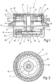
- Fig. 1 shows a manually operated angle encoder 1 with a dial 3, the attached and stored on the outside by means of a shaft 5 on a housing 7 is. All of them are rotatably supported by means of the shaft 5 Parts referred to as the donor element.
- the housing 7 has a housing cover 9 and a pot-shaped lower part 11.
- the housing cover 9 protrudes Formation of a rotationally symmetrical flange 13 laterally over the lower part 11 beyond.
- the angle encoder 1 can, for example can be attached to a control panel or keyboard.
- the housing cover 9 has a disk-shaped in the direction of the housing interior 15 Reinforcement 17, the outer contour of which is essentially the shape of the opening corresponds to the lower part 11.
- the housing cover has in the opposite direction 9 a further disk-shaped reinforcement 19.
- In the middle of the Housing cover 9 is a perpendicular through the reinforcements 17 and 19
- Through hole 21 is provided in the shaft 5 by means of bearings 23 and 25 is mounted radially and axially.
- a tube 27 forms with its outer side 29 the extension of the outer contour of the cylinder of the reinforcement 19.
- On the inside 31 of the tube 27 are in axial distance from each other two disks 33 and 35 with matching Internal gears 37 and 39 arranged without angular misalignment.
- a rotationally symmetrical one Part 43 attached for example by shrinking or gluing, that on its circumference a permanent magnet 45 and two same toothed discs 47 and 49 with external teeth 51 and 53 carries.
- the first toothed pulley 47 is on the side facing the housing 7, the second Toothed washer 49 of the side of the permanent magnet facing away from the housing 7 45 arranged without angular offset with respect to the first toothed disk 47.
- the distance between the two toothed disks 47 and 49 corresponds to the thickness of the Permanent magnet 45 and also determines the distance between the two disks 33 and 35, each arranged concentrically around the toothed disks 47 and 49, respectively are, between the tip circles of the internal gears 37, 39 of the Discs 33, 35 and the external toothings 51, 53 of the toothed discs 47, 49 each has a small radial distance.
- the number of teeth on the toothed disks 47 and 49 matches the number of teeth on the Internal teeth 37 and 39 of the discs 33 and 35 match.
- the Number of teeth on the toothed disks 47 and 49 and the disks 33 and 35 free can be selected, however, the number of teeth hundred is particularly well suited. For simplified representation, only 16 teeth are shown in Fig. 2.
- the toothed disks 47 and 49 as well as the disks 33 and 35 and the tube 27 are made of a material that is the magnetic flux from the permanent magnet 45 goes out, leads well.
- the permanent magnet 45 forms together with the toothed disks 47 and 49, and the discs 33 and 35 and the tube 27 a locking mechanism.
- the permanent magnet 45 with the toothed disks 47 and 49 represents a type Horseshoe magnet and the discs 33 and 35 with the tube 27 a kind of yoke which is attracted the more due to the magnetic flux, ever smaller the radial distance, i.e. the air gap between the disc 33 and the Toothed washer 47 or the washer 35 and the toothed washer 49. This The radial distance is smallest when the teeth of the disks 33, 35 and the toothed disks 47, 49 are directly opposite.
- the number of teeth on the disks 33, 35 and the toothed disks 47, 49 corresponds to the attraction between the whole the horseshoe magnets and yokes in the position shown in Fig. 2 relative high, even if the cogging torque of the individual magnetic circuits is low is.
- a fork 61 On the reinforcement 17 is a fork 61 with a in the housing interior 15 Groove 63 attached. An edge region of the protrudes into this recess 63 Code disc 57.
- a light barrier can in the fork 61 be provided.
- the angle encoder 1 can also be used as an incremental position encoder become.
- a circuit board 65 is arranged on the underside of the fork 61, by means of the built-in chip either the measurement results of the scanning itself converts and thereby a corresponding angular position of the toothed discs 47 and 49 determined to the fixed discs 33 and 35. Alternatively the scanning signals can be forwarded to an external evaluation device become.
- the parts protruding from the housing 7 are covered by means of a the hood-like side of the part 43 facing away from the housing 7 Part 67 of the dial 3.
- This hood-like part 67 serves at the same time to rotate the parts connected to the shaft and thus the Position entry by hand.
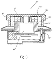
- Fig. 3 shows a second manually operated angle encoder 101, the construction of which is essentially comparable to that of the first embodiment.
- the essential difference is that the permanent magnet 145 is not included the shaft 105, but is connected to the housing 107. Accordingly the pulleys 147 and 149 are also stationary, whereas the Disks 133 and 135 are connected to the setting wheel 103.
- the locking mechanism works according to the first embodiment, wherein however, the moving and stationary parts are interchanged.
- the third exemplary embodiment of an angle encoder 201 is essentially correct with the first and the second embodiment.
- the one with the Housing 207 connected permanent magnet 245 is at the south pole with a Toothed pulley 247 connected.
- This toothed disc 247 is at a radial distance a corresponding disk 235 with a corresponding number of teeth is arranged, which is connected to the setting wheel 203.
- Across from the North Pole a toothless disk 233 is arranged at an axial distance.
- This toothless Washer 233 is connected to the via a tubular connecting element 227 Toothed washer 247 corresponding disk 235 in a magnetically conductive Connection with which the magnetic flux is closed.
- the toothless disc 233 and the tubular connecting element 227 are in the exemplary embodiment formed in one piece, so have the shape of a pot.
- the scanning of the angular position can be modified from the exemplary embodiments outside the housing 7, 107 inside the hood-like part 67 respectively.
- One of the toothed disks 47, 49 or disks 133, 135, 235 can be used.
Landscapes
- Physics & Mathematics (AREA)
- General Physics & Mathematics (AREA)
- Engineering & Computer Science (AREA)
- Automation & Control Theory (AREA)
- Measurement Of Length, Angles, Or The Like Using Electric Or Magnetic Means (AREA)
- Transmission And Conversion Of Sensor Element Output (AREA)
Description
- Fig. 1
- einen Längsschnitt durch ein erstes Ausführungsbeispiel,
- Fig. 2
- einen Querschnitt entlang der Schnittlinie II-II von Fig. 1,
- Fig. 3
- einen Längsschnitt durch ein zweites Ausführungsbeispiel,
- Fig. 4
- einen Längsschnitt durch ein drittes Ausführungsbeispiel.
Claims (9)
- Handbetätigter Winkelgeber (1; 101; 201) mit einem drehbar gelagerten und manuell bewegbaren Geberelement, einem dieses abtastenden Sensor und einem magnetisch und berührungslos wirkenden Rastmechanismus, welcher das Geberelement in definierten, durch die Handbetätigung ineinander überführbaren Winkelpositionen hält, wobei der Rastmechanismus wenigstens einen Permanentmagneten (45; 145; 245) aufweist, dessen Pole (N, S) in axialer Richtung angeordnet sind, wobei auf der Seite wenigstens eines Poles des Permanentmagneten (45; 145; 245) eine Zahnscheibe (47, 49; 147, 149; 247) vorgesehen ist, dadurch gekennzeichnet, daß der Winkelgeber (1; 101;201) in radialem Abstand zu den vorgesehenen Zahnscheiben (47, 49; 147, 149; 247) Scheiben (33, 35; 133, 135; 235) mit entsprechender Zähnezahl aufweist, wobei die vorgesehenen Scheiben (33, 35; 133 135; 235) durch den magnetischen Fluß gut leitendes Material miteinander verbunden sind.
- Winkelgeber nach Anspruch 1, dadurch gekennzeichnet, daß auf der Seite sowohl des Nordpols (N) als auch des Südpols (S) des Permanentmagneten (45; 145) jeweils eine Zahnscheibe (47, 49; 147, 149) mit übereinstimmender Zähnezahl vorgesehen ist.
- Winkelgeber nach Anspruch 1, dadurch gekennzeichnet, daß nur auf der Seite eines Poles (S) des Permanentmagneten (245) eine Zahnscheibe (247) und gegenüber dem anderen Pol (N) in axialem Abstand eine Scheibe (233) vorgesehen ist, welche mit der gegenüber der Zahnscheibe (247) vorgesehenen Scheibe (235) in magnetisch leitender Verbindung steht.
- Winkelgeber nach einem der Ansprüche 1 bis 3, dadurch gekennzeichnet, daß die Zähnezahl der Zahnscheiben (47, 49; 147, 149; 247) und Scheiben (33, 35; 133, 135; 235) größer oder gleich zehn und kleiner oder gleich hundertsechzig ist.
- Winkelgeber nach einem der Ansprüche 1 bis 4, dadurch gekennzeichnet, daß der Rastmechanismus in einem der Handbetätigung dienenden Einstellrad (3; 103; 203) angeordnet ist.
- Winkelgeber nach einem der Ansprüche 1 bis 5, dadurch gekennzeichnet, daß wenigstens ein Teil des Geberelementes innerhalb eines Gehäuses (7; 107; 207) vorgesehen ist.
- Winkelgeber nach Anspruch 6, dadurch gekennzeichnet, daß im Gehäuseinnenraum (15) eine Codescheibe (57) vorgesehen ist, die Teil des Geberelements (8) ist, wobei die Codescheibe (57) vom Sensor abgetastet wird.
- Winkelgeber nach einem der Ansprüche 1 bis 7, dadurch gekennzeichnet, daß der Permanentmagnet (45) Teil des Geberelements ist.
- Winkelgeber nach Anspruch 6 oder 7, dadurch gekennzeichnet, daß der Permanentmagnet (145; 245) fest mit dem Gehäuse (107; 207) verbunden ist.
Applications Claiming Priority (5)
| Application Number | Priority Date | Filing Date | Title |
|---|---|---|---|
| DE19627089 | 1996-07-05 | ||
| DE19627089A DE19627089C1 (de) | 1996-07-05 | 1996-07-05 | Handbetätigter Winkelgeber |
| DE29705744U | 1997-04-01 | ||
| DE29705744U DE29705744U1 (de) | 1996-07-05 | 1997-04-01 | Handbetätigter Winkelgeber |
| PCT/EP1997/003056 WO1998001723A1 (de) | 1996-07-05 | 1997-06-12 | Handbetätigter winkelgeber |
Publications (2)
| Publication Number | Publication Date |
|---|---|
| EP0909372A1 EP0909372A1 (de) | 1999-04-21 |
| EP0909372B1 true EP0909372B1 (de) | 2001-12-19 |
Family
ID=26027232
Family Applications (1)
| Application Number | Title | Priority Date | Filing Date |
|---|---|---|---|
| EP97928180A Expired - Lifetime EP0909372B1 (de) | 1996-07-05 | 1997-06-12 | Handbetätigter Winkelgeber mit radialer Magnetrastierung |
Country Status (5)
| Country | Link |
|---|---|
| US (1) | US6182370B1 (de) |
| EP (1) | EP0909372B1 (de) |
| JP (1) | JP2000513807A (de) |
| AT (1) | ATE211254T1 (de) |
| WO (1) | WO1998001723A1 (de) |
Families Citing this family (9)
| Publication number | Priority date | Publication date | Assignee | Title |
|---|---|---|---|---|
| JP3587674B2 (ja) * | 1998-01-07 | 2004-11-10 | アルプス電気株式会社 | 回転角度センサ、この回転角度センサを用いたトルクセンサ、このトルクセンサを用いた電動パワーステアリング装置 |
| JP2001343207A (ja) * | 2000-03-28 | 2001-12-14 | Tokai Rika Co Ltd | 回転検出センサ |
| FR2908903B1 (fr) * | 2006-11-20 | 2010-09-10 | Valeo Systemes Thermiques | Dispositif d'indexation pour tableau de commande d'un systeme de ventilation,chauffage et/ou climatisation. |
| JP6226425B2 (ja) * | 2014-01-31 | 2017-11-08 | アルプス電気株式会社 | 回転入力装置 |
| JP2016161526A (ja) * | 2015-03-05 | 2016-09-05 | 株式会社ミツトヨ | 接触型プローブ |
| JP2016178038A (ja) * | 2015-03-20 | 2016-10-06 | アルプス電気株式会社 | 回転入力装置 |
| FR3099833B1 (fr) * | 2019-08-07 | 2024-09-13 | Moving Magnet Tech | Interface haptique passive |
| FR3102433B1 (fr) * | 2019-10-23 | 2022-12-16 | Dav | Interface et organe de commande de véhicule automobile |
| FR3108741A1 (fr) * | 2020-03-31 | 2021-10-01 | Moving Magnet Technologies | Dispositif haptique passif |
Family Cites Families (12)
| Publication number | Priority date | Publication date | Assignee | Title |
|---|---|---|---|---|
| US3098300A (en) * | 1958-04-22 | 1963-07-23 | Zeiss Carl | Angle measuring instrument |
| GB999972A (en) * | 1961-02-16 | 1965-07-28 | Data Technology Inc | Position encoding apparatus |
| DE2855635A1 (de) * | 1978-12-22 | 1980-07-10 | Bosch Gmbh Robert | Winkelsegmentgeber mit hall-generator |
| DE3301205C2 (de) * | 1982-02-26 | 1985-10-03 | Dr. Johannes Heidenhain Gmbh, 8225 Traunreut | Winkelmeßeinrichtung |
| DE3590633C2 (de) * | 1984-12-10 | 1991-07-04 | Matsushita Electric Industrial Co., Ltd., Kadoma, Osaka, Jp | |
| SU1325296A1 (ru) * | 1986-03-14 | 1987-07-23 | Московский институт радиотехники, электроники и автоматики | Датчик угла поворота |
| DE4122478A1 (de) * | 1991-02-12 | 1992-08-13 | Bosch Gmbh Robert | Messeinrichtung zur bestimmung eines drehwinkels |
| DE4211615C2 (de) * | 1992-04-07 | 1994-09-22 | Bosch Gmbh Robert | Meßeinrichtung zur Bestimmung eines Drehwinkels |
| JP2698013B2 (ja) * | 1993-01-19 | 1998-01-19 | 彰 石崎 | 位置検出装置 |
| DE4311496C2 (de) * | 1993-04-07 | 1995-05-24 | Euchner & Co | Handbetätigter Winkelgeber |
| DE4436724C2 (de) * | 1994-10-14 | 1997-07-10 | Daimler Benz Aerospace Ag | Elektronischer Positionsgeber |
| US5657544A (en) * | 1995-09-26 | 1997-08-19 | Ntn Corporation | Device for detecting the angle of rotation |
-
1997
- 1997-06-12 JP JP09537481A patent/JP2000513807A/ja active Pending
- 1997-06-12 EP EP97928180A patent/EP0909372B1/de not_active Expired - Lifetime
- 1997-06-12 US US09/180,950 patent/US6182370B1/en not_active Expired - Lifetime
- 1997-06-12 WO PCT/EP1997/003056 patent/WO1998001723A1/de not_active Ceased
- 1997-06-12 AT AT97928180T patent/ATE211254T1/de not_active IP Right Cessation
Also Published As
| Publication number | Publication date |
|---|---|
| WO1998001723A1 (de) | 1998-01-15 |
| JP2000513807A (ja) | 2000-10-17 |
| ATE211254T1 (de) | 2002-01-15 |
| US6182370B1 (en) | 2001-02-06 |
| EP0909372A1 (de) | 1999-04-21 |
Similar Documents
| Publication | Publication Date | Title |
|---|---|---|
| EP1089059B1 (de) | Radauswuchtmaschine für ein Kraftfahrzeugrad mit kompaktem Drehwinkelgeber | |
| EP3403056B1 (de) | Anordnung eines drehwinkelmesssystems an einem gehäuse | |
| DE19630764A1 (de) | Meßvorrichtung zur berührungslosen Erfassung einer Relativbewegung | |
| DE102010024782A1 (de) | Winkelsensor | |
| DE2312729A1 (de) | Kodierer fuer die drehbewegungen einer welle | |
| EP0909372B1 (de) | Handbetätigter Winkelgeber mit radialer Magnetrastierung | |
| DE2921103A1 (de) | Inkrementaler drehgeber | |
| DE102008063951A1 (de) | Winkelsensor | |
| EP1457762B1 (de) | Vorrichtung zur Messung der Position, des Weges oder des Drehwinkels eines Objektes | |
| DE19627089C1 (de) | Handbetätigter Winkelgeber | |
| WO1999030112A1 (de) | Messvorrichtung zur berührungslosen erfassung eines drehwinkels | |
| EP3171137A1 (de) | Drehgeberanordnung | |
| DE69129783T2 (de) | Vorrichtung zur Erfassung einer Drehverstellung einer Blende zum Gebrauch in optischen Systemen | |
| DE4311496C2 (de) | Handbetätigter Winkelgeber | |
| DE3427994A1 (de) | Axial kompakter direktantriebsmotor | |
| EP1131605A1 (de) | Messvorrichtung zur berührunglosen erfassung eines drehwinkels | |
| WO1999030113A1 (de) | Messvorrichtung zur berührungslosen erfassung eines drehwinkels | |
| DE19753775A1 (de) | Meßvorrichtung zur berührungslosen Erfassung eines Drehwinkels | |
| DE19852915A1 (de) | Meßvorrichtung zur berührungslosen Erfassung eines Drehwinkels | |
| DE10010700C1 (de) | Drehgeber mit Rastverhalten | |
| DE69809975T2 (de) | Einrichtung zur Messung der Drehung eines rotierenden Objektes | |
| DE10360016B3 (de) | Bedienvorrichtung mit digitalen Hallsensoren | |
| DE102005025417B4 (de) | Lagegeber | |
| DE4436724A1 (de) | Elektronischer Positionsgeber | |
| WO1998027436A1 (de) | Wirbelstrommesswerk |
Legal Events
| Date | Code | Title | Description |
|---|---|---|---|
| PUAI | Public reference made under article 153(3) epc to a published international application that has entered the european phase |
Free format text: ORIGINAL CODE: 0009012 |
|
| 17P | Request for examination filed |
Effective date: 19981001 |
|
| AK | Designated contracting states |
Kind code of ref document: A1 Designated state(s): AT BE CH DE FR GB IT LI NL SE |
|
| GRAG | Despatch of communication of intention to grant |
Free format text: ORIGINAL CODE: EPIDOS AGRA |
|
| RTI1 | Title (correction) |
Free format text: MANUALLY OPERATED ANGLE PICKUP WITH RADIAL MAGNETIC INDEXING |
|
| GRAG | Despatch of communication of intention to grant |
Free format text: ORIGINAL CODE: EPIDOS AGRA |
|
| GRAH | Despatch of communication of intention to grant a patent |
Free format text: ORIGINAL CODE: EPIDOS IGRA |
|
| 17Q | First examination report despatched |
Effective date: 20010504 |
|
| GRAH | Despatch of communication of intention to grant a patent |
Free format text: ORIGINAL CODE: EPIDOS IGRA |
|
| GRAA | (expected) grant |
Free format text: ORIGINAL CODE: 0009210 |
|
| AK | Designated contracting states |
Kind code of ref document: B1 Designated state(s): AT BE CH DE FR GB IT LI NL SE |
|
| REF | Corresponds to: |
Ref document number: 211254 Country of ref document: AT Date of ref document: 20020115 Kind code of ref document: T |
|
| REG | Reference to a national code |
Ref country code: CH Ref legal event code: NV Representative=s name: ISLER & PEDRAZZINI AG Ref country code: CH Ref legal event code: EP |
|
| REG | Reference to a national code |
Ref country code: GB Ref legal event code: IF02 |
|
| REF | Corresponds to: |
Ref document number: 59705899 Country of ref document: DE Date of ref document: 20020131 |
|
| ET | Fr: translation filed | ||
| GBT | Gb: translation of ep patent filed (gb section 77(6)(a)/1977) |
Effective date: 20020326 |
|
| PLBE | No opposition filed within time limit |
Free format text: ORIGINAL CODE: 0009261 |
|
| STAA | Information on the status of an ep patent application or granted ep patent |
Free format text: STATUS: NO OPPOSITION FILED WITHIN TIME LIMIT |
|
| 26N | No opposition filed | ||
| REG | Reference to a national code |
Ref country code: CH Ref legal event code: PCAR Free format text: ISLER & PEDRAZZINI AG;POSTFACH 1772;8027 ZUERICH (CH) |
|
| PGFP | Annual fee paid to national office [announced via postgrant information from national office to epo] |
Ref country code: NL Payment date: 20090630 Year of fee payment: 13 |
|
| PGFP | Annual fee paid to national office [announced via postgrant information from national office to epo] |
Ref country code: AT Payment date: 20090513 Year of fee payment: 13 |
|
| PGFP | Annual fee paid to national office [announced via postgrant information from national office to epo] |
Ref country code: BE Payment date: 20090608 Year of fee payment: 13 |
|
| PGFP | Annual fee paid to national office [announced via postgrant information from national office to epo] |
Ref country code: CH Payment date: 20090708 Year of fee payment: 13 |
|
| BERE | Be: lapsed |
Owner name: *EUCHNER G.M.B.H. + CO. Effective date: 20100630 |
|
| REG | Reference to a national code |
Ref country code: NL Ref legal event code: V1 Effective date: 20110101 |
|
| REG | Reference to a national code |
Ref country code: CH Ref legal event code: PL |
|
| PG25 | Lapsed in a contracting state [announced via postgrant information from national office to epo] |
Ref country code: IT Free format text: LAPSE BECAUSE OF NON-PAYMENT OF DUE FEES Effective date: 20090612 |
|
| PG25 | Lapsed in a contracting state [announced via postgrant information from national office to epo] |
Ref country code: LI Free format text: LAPSE BECAUSE OF NON-PAYMENT OF DUE FEES Effective date: 20100630 Ref country code: CH Free format text: LAPSE BECAUSE OF NON-PAYMENT OF DUE FEES Effective date: 20100630 |
|
| PG25 | Lapsed in a contracting state [announced via postgrant information from national office to epo] |
Ref country code: NL Free format text: LAPSE BECAUSE OF NON-PAYMENT OF DUE FEES Effective date: 20110101 Ref country code: AT Free format text: LAPSE BECAUSE OF NON-PAYMENT OF DUE FEES Effective date: 20100612 |
|
| PG25 | Lapsed in a contracting state [announced via postgrant information from national office to epo] |
Ref country code: BE Free format text: LAPSE BECAUSE OF NON-PAYMENT OF DUE FEES Effective date: 20100630 |
|
| PGRI | Patent reinstated in contracting state [announced from national office to epo] |
Ref country code: IT Effective date: 20110616 |
|
| REG | Reference to a national code |
Ref country code: FR Ref legal event code: PLFP Year of fee payment: 19 |
|
| REG | Reference to a national code |
Ref country code: DE Ref legal event code: R082 Ref document number: 59705899 Country of ref document: DE Representative=s name: RUCKH, RAINER, DIPL.-PHYS. DR.RER.NAT., DE |
|
| PGFP | Annual fee paid to national office [announced via postgrant information from national office to epo] |
Ref country code: SE Payment date: 20150618 Year of fee payment: 19 Ref country code: GB Payment date: 20150505 Year of fee payment: 19 Ref country code: DE Payment date: 20150529 Year of fee payment: 19 |
|
| PGFP | Annual fee paid to national office [announced via postgrant information from national office to epo] |
Ref country code: FR Payment date: 20150427 Year of fee payment: 19 Ref country code: IT Payment date: 20150622 Year of fee payment: 19 |
|
| REG | Reference to a national code |
Ref country code: DE Ref legal event code: R119 Ref document number: 59705899 Country of ref document: DE |
|
| REG | Reference to a national code |
Ref country code: SE Ref legal event code: EUG |
|
| PG25 | Lapsed in a contracting state [announced via postgrant information from national office to epo] |
Ref country code: SE Free format text: LAPSE BECAUSE OF NON-PAYMENT OF DUE FEES Effective date: 20160613 |
|
| GBPC | Gb: european patent ceased through non-payment of renewal fee |
Effective date: 20160612 |
|
| REG | Reference to a national code |
Ref country code: FR Ref legal event code: ST Effective date: 20170228 |
|
| PG25 | Lapsed in a contracting state [announced via postgrant information from national office to epo] |
Ref country code: FR Free format text: LAPSE BECAUSE OF NON-PAYMENT OF DUE FEES Effective date: 20160630 Ref country code: DE Free format text: LAPSE BECAUSE OF NON-PAYMENT OF DUE FEES Effective date: 20170103 |
|
| PG25 | Lapsed in a contracting state [announced via postgrant information from national office to epo] |
Ref country code: GB Free format text: LAPSE BECAUSE OF NON-PAYMENT OF DUE FEES Effective date: 20160612 |
|
| PG25 | Lapsed in a contracting state [announced via postgrant information from national office to epo] |
Ref country code: IT Free format text: LAPSE BECAUSE OF NON-PAYMENT OF DUE FEES Effective date: 20160612 |