EP0909372B1 - Manually operated angle pickup with radial magnetic indexing - Google Patents
Manually operated angle pickup with radial magnetic indexing Download PDFInfo
- Publication number
- EP0909372B1 EP0909372B1 EP97928180A EP97928180A EP0909372B1 EP 0909372 B1 EP0909372 B1 EP 0909372B1 EP 97928180 A EP97928180 A EP 97928180A EP 97928180 A EP97928180 A EP 97928180A EP 0909372 B1 EP0909372 B1 EP 0909372B1
- Authority
- EP
- European Patent Office
- Prior art keywords
- permanent magnet
- angle sensor
- toothed
- disc
- sensor according
- Prior art date
- Legal status (The legal status is an assumption and is not a legal conclusion. Google has not performed a legal analysis and makes no representation as to the accuracy of the status listed.)
- Expired - Lifetime
Links
Images

Classifications
-
- G—PHYSICS
- G01—MEASURING; TESTING
- G01D—MEASURING NOT SPECIALLY ADAPTED FOR A SPECIFIC VARIABLE; ARRANGEMENTS FOR MEASURING TWO OR MORE VARIABLES NOT COVERED IN A SINGLE OTHER SUBCLASS; TARIFF METERING APPARATUS; MEASURING OR TESTING NOT OTHERWISE PROVIDED FOR
- G01D5/00—Mechanical means for transferring the output of a sensing member; Means for converting the output of a sensing member to another variable where the form or nature of the sensing member does not constrain the means for converting; Transducers not specially adapted for a specific variable
- G01D5/12—Mechanical means for transferring the output of a sensing member; Means for converting the output of a sensing member to another variable where the form or nature of the sensing member does not constrain the means for converting; Transducers not specially adapted for a specific variable using electric or magnetic means
- G01D5/244—Mechanical means for transferring the output of a sensing member; Means for converting the output of a sensing member to another variable where the form or nature of the sensing member does not constrain the means for converting; Transducers not specially adapted for a specific variable using electric or magnetic means influencing characteristics of pulses or pulse trains; generating pulses or pulse trains
- G01D5/245—Mechanical means for transferring the output of a sensing member; Means for converting the output of a sensing member to another variable where the form or nature of the sensing member does not constrain the means for converting; Transducers not specially adapted for a specific variable using electric or magnetic means influencing characteristics of pulses or pulse trains; generating pulses or pulse trains using a variable number of pulses in a train
- G01D5/2451—Incremental encoders
-
- G—PHYSICS
- G05—CONTROLLING; REGULATING
- G05G—CONTROL DEVICES OR SYSTEMS INSOFAR AS CHARACTERISED BY MECHANICAL FEATURES ONLY
- G05G5/00—Means for preventing, limiting or returning the movements of parts of a control mechanism, e.g. locking controlling member
- G05G5/06—Means for preventing, limiting or returning the movements of parts of a control mechanism, e.g. locking controlling member for holding members in one or a limited number of definite positions only
-
- H—ELECTRICITY
- H01—ELECTRIC ELEMENTS
- H01H—ELECTRIC SWITCHES; RELAYS; SELECTORS; EMERGENCY PROTECTIVE DEVICES
- H01H5/00—Snap-action arrangements, i.e. in which during a single opening operation or a single closing operation energy is first stored and then released to produce or assist the contact movement
- H01H5/02—Energy stored by the attraction or repulsion of magnetic parts
-
- G—PHYSICS
- G05—CONTROLLING; REGULATING
- G05G—CONTROL DEVICES OR SYSTEMS INSOFAR AS CHARACTERISED BY MECHANICAL FEATURES ONLY
- G05G1/00—Controlling members, e.g. knobs or handles; Assemblies or arrangements thereof; Indicating position of controlling members
- G05G1/08—Controlling members for hand actuation by rotary movement, e.g. hand wheels
-
- H—ELECTRICITY
- H01—ELECTRIC ELEMENTS
- H01H—ELECTRIC SWITCHES; RELAYS; SELECTORS; EMERGENCY PROTECTIVE DEVICES
- H01H3/00—Mechanisms for operating contacts
- H01H3/32—Driving mechanisms, i.e. for transmitting driving force to the contacts
- H01H3/50—Driving mechanisms, i.e. for transmitting driving force to the contacts with indexing or locating means, e.g. indexing by ball and spring
- H01H2003/506—Driving mechanisms, i.e. for transmitting driving force to the contacts with indexing or locating means, e.g. indexing by ball and spring making use of permanent magnets
-
- Y—GENERAL TAGGING OF NEW TECHNOLOGICAL DEVELOPMENTS; GENERAL TAGGING OF CROSS-SECTIONAL TECHNOLOGIES SPANNING OVER SEVERAL SECTIONS OF THE IPC; TECHNICAL SUBJECTS COVERED BY FORMER USPC CROSS-REFERENCE ART COLLECTIONS [XRACs] AND DIGESTS
- Y10—TECHNICAL SUBJECTS COVERED BY FORMER USPC
- Y10S—TECHNICAL SUBJECTS COVERED BY FORMER USPC CROSS-REFERENCE ART COLLECTIONS [XRACs] AND DIGESTS
- Y10S33/00—Geometrical instruments
- Y10S33/01—Magnetic
Definitions
- the invention relates to a manually operated angle encoder with the features the preamble of claim 1.
- a known angle encoder of this type (DE 43 11 496 C2) is the encoder element a disc, the outer edge of which is formed by tongues, the are bent so that they are part of their length in one to the axis of rotation of the encoder element are concentric cylinder surface. Concentric to this cylinder surface and at a smaller radial distance from it in the circumferential direction alternating north and south poles are one the second part of the locking mechanism associated magnet provided.
- the invention is therefore based on the object of a manually operated angle encoder to create that builds smaller with the same division and is also realistic permits large installation tolerances without being impaired in its function.
- the axial arrangement of the north-south poles enables miniaturization, especially in the radial direction.
- the diameter of the angle encoder regardless of minimum distances between different poles.
- Both sides of the permanent magnet are particularly well suited for miniaturization arranged toothed disks and disks corresponding to them, are connected to each other for example by a tube.
- the exist Toothed lock washers, the washers and their connecting element made of one material, that conducts the magnetic flux well. Varies due to the contour of the teeth the air gap between toothed washers and washers, the magnetic Flow and thus the attraction of the teeth of the toothed washers and washers on largest is when the teeth face each other directly.
- Both poles can each be connected to a toothed washer, the corresponding discs are arranged at a radial distance. But it is it is also possible that only one of the two poles is connected to a toothed disk is and only a corresponding disc is provided at a radial distance. A toothless disk is then at an axial distance from the other pole arranged, the disc corresponding to the toothed disc over a Connection element is in a magnetically conductive connection.
- the toothless Washer can be a single component or with the connecting element be made in one piece in the manner of a pot.
- the number of teeth one hundred enables particularly good handling of the Angle encoder for quick and precise setting or input, for example of coordinates in a CNC control. Further preferred number of teeth are sixteen, thirty-two, fifty or sixty, but should be Teeth range from ten to one hundred and sixty for easy handling to ensure.
- the angle encoder becomes particularly compact when the locking mechanism is directly is provided in the setting wheel.
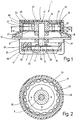
- Fig. 1 shows a manually operated angle encoder 1 with a dial 3, the attached and stored on the outside by means of a shaft 5 on a housing 7 is. All of them are rotatably supported by means of the shaft 5 Parts referred to as the donor element.
- the housing 7 has a housing cover 9 and a pot-shaped lower part 11.
- the housing cover 9 protrudes Formation of a rotationally symmetrical flange 13 laterally over the lower part 11 beyond.
- the angle encoder 1 can, for example can be attached to a control panel or keyboard.
- the housing cover 9 has a disk-shaped in the direction of the housing interior 15 Reinforcement 17, the outer contour of which is essentially the shape of the opening corresponds to the lower part 11.
- the housing cover has in the opposite direction 9 a further disk-shaped reinforcement 19.
- In the middle of the Housing cover 9 is a perpendicular through the reinforcements 17 and 19
- Through hole 21 is provided in the shaft 5 by means of bearings 23 and 25 is mounted radially and axially.
- a tube 27 forms with its outer side 29 the extension of the outer contour of the cylinder of the reinforcement 19.
- On the inside 31 of the tube 27 are in axial distance from each other two disks 33 and 35 with matching Internal gears 37 and 39 arranged without angular misalignment.
- a rotationally symmetrical one Part 43 attached for example by shrinking or gluing, that on its circumference a permanent magnet 45 and two same toothed discs 47 and 49 with external teeth 51 and 53 carries.
- the first toothed pulley 47 is on the side facing the housing 7, the second Toothed washer 49 of the side of the permanent magnet facing away from the housing 7 45 arranged without angular offset with respect to the first toothed disk 47.
- the distance between the two toothed disks 47 and 49 corresponds to the thickness of the Permanent magnet 45 and also determines the distance between the two disks 33 and 35, each arranged concentrically around the toothed disks 47 and 49, respectively are, between the tip circles of the internal gears 37, 39 of the Discs 33, 35 and the external toothings 51, 53 of the toothed discs 47, 49 each has a small radial distance.
- the number of teeth on the toothed disks 47 and 49 matches the number of teeth on the Internal teeth 37 and 39 of the discs 33 and 35 match.
- the Number of teeth on the toothed disks 47 and 49 and the disks 33 and 35 free can be selected, however, the number of teeth hundred is particularly well suited. For simplified representation, only 16 teeth are shown in Fig. 2.
- the toothed disks 47 and 49 as well as the disks 33 and 35 and the tube 27 are made of a material that is the magnetic flux from the permanent magnet 45 goes out, leads well.
- the permanent magnet 45 forms together with the toothed disks 47 and 49, and the discs 33 and 35 and the tube 27 a locking mechanism.
- the permanent magnet 45 with the toothed disks 47 and 49 represents a type Horseshoe magnet and the discs 33 and 35 with the tube 27 a kind of yoke which is attracted the more due to the magnetic flux, ever smaller the radial distance, i.e. the air gap between the disc 33 and the Toothed washer 47 or the washer 35 and the toothed washer 49. This The radial distance is smallest when the teeth of the disks 33, 35 and the toothed disks 47, 49 are directly opposite.
- the number of teeth on the disks 33, 35 and the toothed disks 47, 49 corresponds to the attraction between the whole the horseshoe magnets and yokes in the position shown in Fig. 2 relative high, even if the cogging torque of the individual magnetic circuits is low is.
- a fork 61 On the reinforcement 17 is a fork 61 with a in the housing interior 15 Groove 63 attached. An edge region of the protrudes into this recess 63 Code disc 57.
- a light barrier can in the fork 61 be provided.
- the angle encoder 1 can also be used as an incremental position encoder become.
- a circuit board 65 is arranged on the underside of the fork 61, by means of the built-in chip either the measurement results of the scanning itself converts and thereby a corresponding angular position of the toothed discs 47 and 49 determined to the fixed discs 33 and 35. Alternatively the scanning signals can be forwarded to an external evaluation device become.
- the parts protruding from the housing 7 are covered by means of a the hood-like side of the part 43 facing away from the housing 7 Part 67 of the dial 3.
- This hood-like part 67 serves at the same time to rotate the parts connected to the shaft and thus the Position entry by hand.
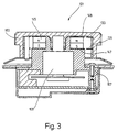
- Fig. 3 shows a second manually operated angle encoder 101, the construction of which is essentially comparable to that of the first embodiment.
- the essential difference is that the permanent magnet 145 is not included the shaft 105, but is connected to the housing 107. Accordingly the pulleys 147 and 149 are also stationary, whereas the Disks 133 and 135 are connected to the setting wheel 103.
- the locking mechanism works according to the first embodiment, wherein however, the moving and stationary parts are interchanged.
- the third exemplary embodiment of an angle encoder 201 is essentially correct with the first and the second embodiment.
- the one with the Housing 207 connected permanent magnet 245 is at the south pole with a Toothed pulley 247 connected.
- This toothed disc 247 is at a radial distance a corresponding disk 235 with a corresponding number of teeth is arranged, which is connected to the setting wheel 203.
- Across from the North Pole a toothless disk 233 is arranged at an axial distance.
- This toothless Washer 233 is connected to the via a tubular connecting element 227 Toothed washer 247 corresponding disk 235 in a magnetically conductive Connection with which the magnetic flux is closed.
- the toothless disc 233 and the tubular connecting element 227 are in the exemplary embodiment formed in one piece, so have the shape of a pot.
- the scanning of the angular position can be modified from the exemplary embodiments outside the housing 7, 107 inside the hood-like part 67 respectively.
- One of the toothed disks 47, 49 or disks 133, 135, 235 can be used.
Abstract
Description
Die Erfindung betrifft einen handbetätigten Winkelgeber mit den Merkmalen
des Oberbegriffs des Anspruches 1.The invention relates to a manually operated angle encoder with the features
the preamble of
Bei einem bekannten Winkelgeber dieser Art (DE 43 11 496 C2) ist das Geberelement
eine Scheibe, deren äußere Randzone durch Zungen gebildet wird, die
derart umgebogen sind, daß sie auf einem Teil ihrer Länge in einer zur Drehachse
des Geberelements konzentrischen Zylinderfläche liegen. Konzentrisch
zu dieser Zylinderfläche und in geringerem radialem Abstand von ihr in Umfangsrichtung
sind im Wechsel aufeinanderfolgende Nord- und Südpole eines
dem zweiten Teil des Rastmechanismus zugeordneten Magneten vorgesehen.In a known angle encoder of this type (
Bei vorgegebener Teilung ist eine bestimmte Mindestgröße erforderlich, die aufgrund des erforderlichen Polabstandes fest vorgegeben ist.With a given division a certain minimum size is required, which is fixed due to the required pole spacing is specified.
Aus der DE 44 36 724 A1 ist ferner ein elektronischer Positionsgeber mit einem magnetischen Rastsystem bekannt, bei dem die Magnetverrastung mindestens drei zueinander koaxiale wechselweise wellen- und trägerfeste, jeweils über den gesamten Scheibenumfang radial genutete Magnetrastscheiben enthält. From DE 44 36 724 A1 an electronic position transmitter with a known magnetic locking system, in which the magnetic locking at least three mutually coaxial, alternately shaft and carrier fixed, each over contains the entire disc circumference radially grooved magnetic locking discs.
Die Anziehungskraft zwischen den einzelnen Magnetrastscheiben wird durch axialen Versatz verringert. Somit sind nur geringe Toleranzen bei der Fertigung möglich.The attraction between the individual magnetic locking disks are reduced by axial misalignment. So are only small tolerances in production possible.
Der Erfindung liegt daher die Aufgabe zugrunde, einen handbetätigten Winkelgeber zu schaffen, der bei gleicher Teilung kleiner baut und zudem realtiv große Einbautoleranzen zuläßt, ohne in seiner Funktion beeinträchtigt zu sein.The invention is therefore based on the object of a manually operated angle encoder to create that builds smaller with the same division and is also realistic permits large installation tolerances without being impaired in its function.
Diese Aufgabe löst ein handbetätigten Winkelgeber mit den Merkmalen des Anspruches 1.This task is solved by a manually operated angle encoder with the features of
Die axiale Anordnung der Nord-Südpole ermöglicht eine Miniaturisierung, insbesondere in radialer Richtung. Dabei ist der Durchmesser des Winkelgebers unabhängig von Mindestabständen unterschiedlicher Pole.The axial arrangement of the north-south poles enables miniaturization, especially in the radial direction. Here is the diameter of the angle encoder regardless of minimum distances between different poles.
Besonders kostengünstig ist die Verwendung eines einzigen Permanentmagneten. Ein Montagefehler aufgrund falscher Einbaurichtung kann bei dieser Ausgestaltung nicht vorkommen.The use of a single permanent magnet is particularly cost-effective. An assembly error due to incorrect installation direction can occur with this configuration do not occur.
Besonders gut zur Miniaturisierung geeignet sind beidseitig des Permanentmagneten angeordnete Zahnscheiben und zu diesen korrespondierende Scheiben, beispielsweise durch ein Rohr miteinander verbunden sind. Dabei bestehen die Zahnscheiben, die Scheiben und deren Verbindungselement aus einem Material, das den magnetischen Fluß gut leitet. Aufgrund der Kontur der Zähne variiert der Luftspalt zwischen Zahnscheiben und Scheiben, wobei der magnetische Fluß und somit die Anziehung der Zähne der Zahnscheiben und Scheiben am größten ist, wenn sich die Zähne direkt gegenüberliegen.Both sides of the permanent magnet are particularly well suited for miniaturization arranged toothed disks and disks corresponding to them, are connected to each other for example by a tube. The exist Toothed lock washers, the washers and their connecting element made of one material, that conducts the magnetic flux well. Varies due to the contour of the teeth the air gap between toothed washers and washers, the magnetic Flow and thus the attraction of the teeth of the toothed washers and washers on largest is when the teeth face each other directly.
Es können beide Pole mit jeweils einer Zahnscheibe verbunden sein, wobei die korrespondierenden Scheiben in radialem Abstand angeordnet sind. Es ist aber auch möglich, daß nur einer der beiden Pole mit einer Zahnscheibe verbunden ist und nur eine korrespondierende Scheibe in radialem Abstand vorgesehen ist. Gegenüber dem anderen Pol ist dann in axialem Abstand eine zahnlose Scheibe angeordnet, die zur Zahnscheibe korrespondierende Scheibe über ein Verbindungselement in magnetisch leitender Verbindung steht. Die zahnlose Scheibe kann dabei ein einzelnes Bauteil sein oder mit dem Verbindungselement in der Art eines Topfes einstückig ausgebildet sein.Both poles can each be connected to a toothed washer, the corresponding discs are arranged at a radial distance. But it is it is also possible that only one of the two poles is connected to a toothed disk is and only a corresponding disc is provided at a radial distance. A toothless disk is then at an axial distance from the other pole arranged, the disc corresponding to the toothed disc over a Connection element is in a magnetically conductive connection. The toothless Washer can be a single component or with the connecting element be made in one piece in the manner of a pot.
Die Zähnezahl hundert ermöglicht eine besonders gute Handhabung des Winkelgebers zur schnellen und genauen Einstellung oder Eingabe, beispielsweise von Koordinaten bei einer CNC-Steuerung. Weitere bevorzugte Zähnezahlen sind sechzehn, zweiunddreißig, fünfzig oder sechzig, jedoch sollte die Zähnezahl im Bereich zehn bis hundertsechzig liegen, um eine gute Handhabung zu gewährleisten.The number of teeth one hundred enables particularly good handling of the Angle encoder for quick and precise setting or input, for example of coordinates in a CNC control. Further preferred number of teeth are sixteen, thirty-two, fifty or sixty, but should be Teeth range from ten to one hundred and sixty for easy handling to ensure.
Besonders kompakt wird der Winkelgeber, wenn der Rastmechanismus direkt im Einstellrad vorgesehen ist.The angle encoder becomes particularly compact when the locking mechanism is directly is provided in the setting wheel.
Weitere vorteilhafte Ausgestaltungen sind den Unteransprüchen zu entnehmen.Further advantageous refinements can be found in the subclaims.
Im folgenden ist die Erfindung anhand dreier in den Zeichnungen dargestellten Ausführungsbeispiele im einzelnen erläutert. Es zeigen
- Fig. 1
- einen Längsschnitt durch ein erstes Ausführungsbeispiel,
- Fig. 2
- einen Querschnitt entlang der Schnittlinie II-II von Fig. 1,
- Fig. 3
- einen Längsschnitt durch ein zweites Ausführungsbeispiel,
- Fig. 4
- einen Längsschnitt durch ein drittes Ausführungsbeispiel.
- Fig. 1
- 2 shows a longitudinal section through a first exemplary embodiment,
- Fig. 2
- 2 shows a cross section along the section line II-II from FIG. 1,
- Fig. 3
- 2 shows a longitudinal section through a second exemplary embodiment,
- Fig. 4
- a longitudinal section through a third embodiment.
Fig. 1 zeigt einen handbetätigten Winkelgeber 1 mit einem Einstellrad 3, das
mittels einer Welle 5 an einem Gehäuse 7 außenseitig angebracht und gelagert
ist. In der Gesamtheit werden sämtliche mittels der Welle 5 drehbar gelagerten
Teile als Geberelement bezeichnet. Das Gehäuse 7 weist einen Gehäusedekkel
9 und ein topfförmiges Unterteil 11 auf. Der Gehäusedeckel 9 ragt unter
Bildung eines rotationssymmetrischen Flansches 13 seitlich über das Unterteil
11 hinaus. Mit Hilfe des Flansches 13 kann der Winkelgeber 1 beispielsweise
in einer Schalttafel oder Tastatur befestigt werden.Fig. 1 shows a manually operated
Der Gehäusedeckel 9 hat in Richtung des Gehäuseinnenraums 15 eine scheibenförmige
Verstärkung 17, deren Außenkontur im wesentlichen der Öffnungsform
des Unterteils 11 entspricht. In entgegegesetzter Richtung hat der Gehäusedeckel
9 eine weitere scheibenförmige Verstärkung 19. In der Mitte des
Gehäusedeckels 9 ist eine senkrecht durch die Verstärkungen 17 und 19 verlaufende
Durchgangsbohrung 21 vorgesehen, in der die Welle 5 mittels Lager
23 und 25 radial und axial gelagert ist.The housing cover 9 has a disk-shaped in the direction of the
Ein Rohr 27 bildet mit seiner Außenseite 29 die Verlängerung der Außenkontur
des Zylinders der Verstärkung 19. Auf der Innenseite 31 des Rohres 27 sind in
axialem Abstand voneinander zwei Scheiben 33 und 35 mit übereinstimmenden
Innenverzahnungen 37 und 39 ohne Winkelversatz angeordnet.A
Am aus dem Gehäuse 7 ragenden Ende 41 der Welle 5 ist ein rotationssymmetrisches
Teil 43 beispielsweise durch Aufschrumpfen oder Einkleben angebracht,
das an seinem Umfang einen Permanentmagneten 45 und zwei
gleiche Zahnscheiben 47 und 49 mit Außenverzahnungen 51 und 53 trägt. Die
erste Zahnscheibe 47 ist auf der dem Gehäuse 7 zugewandten Seite, die zweite
Zahnscheibe 49 der dem Gehäuse 7 abgewandten Seite des Permanentmagneten
45 ohne Winkelversatz bezüglich der ersten Zahnscheibe 47 angeordnet.
Der Abstand der beiden Zahnscheiben 47 und 49 entspricht der Dicke des
Permanentmagneten 45 und bestimmt auch den Abstand der beiden Scheiben
33 und 35, die jeweils konzentrisch um die Zahnscheiben 47 bzw. 49 angeordnet
sind, wobei zwischen den Kopfkreisen der Innenverzahnungen 37, 39 der
Scheiben 33,35 und den Außenverzahnungen 51, 53 der Zahnscheiben 47, 49
jeweils ein geringer radialer Abstand besteht.At the
Die Zähnezahl der Zahnscheiben 47 und 49 stimmt mit der Zähnezahl der
Innenverzahnung 37 und 39 der Scheiben 33 und 35 überein. Dabei kann die
Zähnezahl der Zahnscheiben 47 und 49 und der Scheiben 33 und 35 frei
gewählt werden, jedoch ist die Zähnezahl hundert besonders gut geeignet. Zur
vereinfachten Darstellung sind in Fig. 2 nur 16 Zähne dargestellt.The number of teeth on the
Die Zahnscheiben 47 und 49 wie auch die Scheiben 33 und 35 und das Rohr
27 bestehen aus einem Material, das den magnetischen Fluß, der vom Permanentmagneten
45 ausgeht, gut leitet.The
Der Permanentmagnet 45 bildet zusammen mit den Zahnscheiben 47 und 49,
sowie den Scheiben 33 und 35 und dem Rohr 27 einen Rastmechanismus.
Dabei stellt der Permanentmagnet 45 mit den Zahnscheiben 47 und 49 eine Art
Hufeisenmagnet und die Scheiben 33 und 35 mit dem Rohr 27 eine Art Joch
dar, das aufgrund des magnetischen Flusses um so stärker angezogen wird, je
kleiner der radiale Abstand, d.h. der Luftspalt zwischen der Scheibe 33 und der
Zahnscheibe 47 bzw. der Scheibe 35 und der Zahnscheibe 49 ist. Dieser
radiale Abstand ist am kleinsten, wenn sich die Zähne der Scheiben 33, 35 und
der Zahnscheiben 47, 49 direkt gegenüberliegen. Aufgrund der Vielzahl der
magnetischen Kreise, die der Zähnezahl der Scheiben 33, 35 und der Zahnscheiben
47, 49 entspricht, ist die Anziehungskraft zwischen der Gesamtheit
der Hufeisenmagnete und Joche in der in Fig. 2 dargestellten Stellung relativ
hoch, auch wenn das Rastmoment der einzelnen magnetischen Kreise gering
ist. The
Am im Gehäuseinnenraum 15 befindlichen Ende 55 der Welle 5 ist eine runde
Codescheibe 57 angebracht. Zur Vergrößerung der Anlagefläche zwischen
Codescheibe 57 und der Welle 5 ist konzentrisch zur Welle 5 an deren Ende
55 ein Ring 59 angeordnet, der auf seiner an der Codescheibe 57 zugewandten
Seite zusammen mit dem Ende 55 eine plane Fläche bildet.At the
An der Verstärkung 17 ist im Gehäuseinnenraum 15 eine Gabel 61 mit einer
Aüsnehmung 63 angebracht. In diese Ausnehmung 63 ragt ein Randbereich der
Codescheibe 57. Als Sensor, der bei jeder Drehung der Welle 5 in die nächste
Rastposition ein impulsartiges Signal erzeugt, kann in der Gabel 61 eine Lichtschranke
vorgesehen sein. Wenn der Sensor ein impulsartiges Signal erzeugt,
so kann der Winkelgeber 1 auch als inkrementaler Positionsgeber verwendet
werden. Auf der Unterseite der Gabel 61 ist eine Leiterplatte 65 angeordnet,
die mittels eingebauten Chip entweder die Meßergebnisse der Abtastung selbst
umwandelt und dadurch eine entsprechende Winkelstellung der Zahnscheiben
47 und 49 zu den feststehenden Scheiben 33 und 35 ermittelt. Alternativ dazu
können die Abtastsignale an eine externe Auswertevorrichtung weitergeleitet
werden.On the
Die Abdeckung der aus dem Gehäuse 7 ragenden Teile erfolgt mittels eines an
der dem Gehäuse 7 abgewandten Seite des Teiles 43 angebrachten haubenartigen
Teiles 67 des Einstellrades 3. Dieses haubenartige Teil 67 dient gleichzeitig
zur Verdrehung der mit der Welle verbundenen Teile und somit der
Positionseingabe von Hand.The parts protruding from the housing 7 are covered by means of a
the hood-like side of the
Fig. 3 zeigt einen zweiten handbetätigten Winkelgeber 101, dessen Aufbau im
wesentlichen mit dem des ersten Ausführungsbeispiels vergleichbar ist. Der
wesentliche Unterschied besteht darin, daß der Permanentmagnet 145 nicht mit
der Welle 105, sondern mit dem Gehäuse 107 verbunden ist. Dementsprechend
sind auch die Zahnscheiben 147 und 149 ortsfest, wohingegen die
Scheiben 133 und 135 mit dem Einstellrad 103 verbunden sind. Der Rastmechanismus
funktioniert entsprechend dem ersten Ausführungsbeispiel, wobei
jedoch die bewegten und die stationären Teile vertauscht sind.Fig. 3 shows a second manually operated
Das dritte Ausführungsbeispiel eines Winkelgebers 201 stimmt im wesentlichen
mit dem ersten und dem zweiten Ausführungsbeispiel überein. Der mit dem
Gehäuse 207 verbundene Permanentmagnet 245 ist am Südpol mit einer
Zahnscheibe 247 verbunden. Dieser Zahnscheibe 247 ist in radialem Abstand
eine korrespondierende Scheibe 235 mit entsprechender Zähnezahl angeordnet,
welche mit dem Einstellrad 203 verbunden ist. Gegenüber dem Nordpol ist
in axialem Abstand eine zahnlose Scheibe 233 angeordnet. Diese zahnlose
Scheibe 233 steht über ein rohrförmiges Verbindungselement 227 mit der zur
Zahnscheibe 247 korrespondierenden Scheibe 235 in magnetisch leitender
Verbindung, womit der magnetische Fluß geschlossen ist. Die zahnlose Scheibe
233 und das rohrförmige Verbindungselement 227 sind im Ausführungsbeispiel
einstückig ausgebildet, weisen also die Form eines Topfes auf.The third exemplary embodiment of an
Die Abtastung der Winkelstellung kann in Abwandlung der Ausführungsbeispiele
außerhalb des Gehäuses 7, 107 innerhalb des haubenartigen Teiles 67
erfolgen. Hierfür kann eine der Zahnscheiben 47, 49 bzw. der Scheiben 133,
135, 235 verwendet werden.The scanning of the angular position can be modified from the exemplary embodiments
outside the
Claims (9)
- Manually activated angle sensor (1; 101; 201) having a rotationally arranged and manually movable sensor element, a pickup which scans the sensor element and a magnetically and contactlessly functioning latching mechanism which holds the sensor element in defined angular positions, which can be changed from one to the other by manual activation, the latching mechanism having at least one permanent magnet (45; 145; 245) whose poles (N, S) are arranged in an axial direction, a toothed disc (47, 49; 147, 149; 247) being provided at the side of at least one pole of the permanent magnet (45; 145; 245), characterised in that the angle sensor (1; 101; 201) has discs (33, 35; 133, 135; 235) having a corresponding number of teeth with radial spacing from the toothed discs (47, 49; 147, 149; 247) provided, the discs (33, 35; 133, 135; 235) provided being connected to each other by the magnetic flux of highly conductive material.
- Angle sensor according to claim 1, characterised in that a toothed disc (47, 49; 147, 149) having a matching number of teeth is provided at the side both of the north pole (N) and the south pole (S) of the permanent magnet (45; 145).
- Angle sensor according to claim 1, characterised in that a toothed disc (247) is provided only at the side of one pole (S) of the permanent magnet (245) and a disc (233) is provided with axial spacing opposite the other pole (N), which disc (233) is connected in a magnetically conductive manner to the disc (235) provided opposite the toothed disc (247).
- Angle sensor according to any one of claims 1 to 3, characterised in that the number of teeth of the toothed discs (47, 49; 147, 149; 247) and discs (33, 35; 133, 135; 235) is greater than or equal to ten and less than or equal to one hundred and sixty.
- Angle sensor according to any one of claims 1 to 4, characterised in that the latching mechanism is arranged in an adjustment wheel (3, 103; 203) which is used for the manual activation.
- Angle sensor according to any one of claims 1 to 5, characterised in that at least a portion of the sensor element is provided within a housing (7; 107; 207).
- Angle sensor according to claim 6, characterised in that a code disc (57) is provided in the housing interior (15) and is part of the sensor element (8), the code disc (57) being scanned by the pickup.
- Angle sensor according to any one of claims 1 to 7, characterised in that the permanent magnet (45) is part of the sensor element.
- Angle sensor according to claim 6 or claim 7, characterised in that the permanent magnet (145; 245) is securely connected to the housing (107; 207).
Applications Claiming Priority (5)
| Application Number | Priority Date | Filing Date | Title |
|---|---|---|---|
| DE19627089 | 1996-07-05 | ||
| DE19627089A DE19627089C1 (en) | 1996-07-05 | 1996-07-05 | Manually-operated angle indicator for electronic position transmitter |
| DE29705744U DE29705744U1 (en) | 1996-07-05 | 1997-04-01 | Manual angle encoder |
| DE29705744U | 1997-04-01 | ||
| PCT/EP1997/003056 WO1998001723A1 (en) | 1996-07-05 | 1997-06-12 | Manually operated angle pickup |
Publications (2)
| Publication Number | Publication Date |
|---|---|
| EP0909372A1 EP0909372A1 (en) | 1999-04-21 |
| EP0909372B1 true EP0909372B1 (en) | 2001-12-19 |
Family
ID=26027232
Family Applications (1)
| Application Number | Title | Priority Date | Filing Date |
|---|---|---|---|
| EP97928180A Expired - Lifetime EP0909372B1 (en) | 1996-07-05 | 1997-06-12 | Manually operated angle pickup with radial magnetic indexing |
Country Status (5)
| Country | Link |
|---|---|
| US (1) | US6182370B1 (en) |
| EP (1) | EP0909372B1 (en) |
| JP (1) | JP2000513807A (en) |
| AT (1) | ATE211254T1 (en) |
| WO (1) | WO1998001723A1 (en) |
Families Citing this family (9)
| Publication number | Priority date | Publication date | Assignee | Title |
|---|---|---|---|---|
| JP3587674B2 (en) * | 1998-01-07 | 2004-11-10 | アルプス電気株式会社 | Rotation angle sensor, torque sensor using this rotation angle sensor, electric power steering device using this torque sensor |
| JP2001343207A (en) * | 2000-03-28 | 2001-12-14 | Tokai Rika Co Ltd | Rotation detection sensor |
| FR2908903B1 (en) * | 2006-11-20 | 2010-09-10 | Valeo Systemes Thermiques | INDEXING DEVICE FOR A CONTROL PANEL OF A VENTILATION, HEATING AND / OR AIR CONDITIONING SYSTEM. |
| JP6226425B2 (en) * | 2014-01-31 | 2017-11-08 | アルプス電気株式会社 | Rotation input device |
| JP2016161526A (en) * | 2015-03-05 | 2016-09-05 | 株式会社ミツトヨ | Contact type probe |
| JP2016178038A (en) * | 2015-03-20 | 2016-10-06 | アルプス電気株式会社 | Rotary input device |
| FR3099833A1 (en) * | 2019-08-07 | 2021-02-12 | Moving Magnet Technologies | Passive haptic interface |
| FR3102433B1 (en) * | 2019-10-23 | 2022-12-16 | Dav | Motor vehicle interface and controller |
| FR3108741A1 (en) * | 2020-03-31 | 2021-10-01 | Moving Magnet Technologies | Passive haptic device |
Family Cites Families (12)
| Publication number | Priority date | Publication date | Assignee | Title |
|---|---|---|---|---|
| US3098300A (en) * | 1958-04-22 | 1963-07-23 | Zeiss Carl | Angle measuring instrument |
| GB999972A (en) * | 1961-02-16 | 1965-07-28 | Data Technology Inc | Position encoding apparatus |
| DE2855635A1 (en) * | 1978-12-22 | 1980-07-10 | Bosch Gmbh Robert | Rotation angle sensor including Hall generator - has revolving disc with projecting ring zones which define segments |
| DE3301205C2 (en) * | 1982-02-26 | 1985-10-03 | Dr. Johannes Heidenhain Gmbh, 8225 Traunreut | Angle measuring device |
| DE3590633T (en) | 1984-12-10 | 1987-03-12 | ||
| SU1325296A1 (en) * | 1986-03-14 | 1987-07-23 | Московский институт радиотехники, электроники и автоматики | Turning angle transducer |
| DE4122478A1 (en) * | 1991-02-12 | 1992-08-13 | Bosch Gmbh Robert | MEASURING DEVICE FOR DETERMINING A TURNING ANGLE |
| DE4211615C2 (en) * | 1992-04-07 | 1994-09-22 | Bosch Gmbh Robert | Measuring device for determining an angle of rotation |
| JP2698013B2 (en) * | 1993-01-19 | 1998-01-19 | 彰 石崎 | Position detection device |
| DE4311496C2 (en) * | 1993-04-07 | 1995-05-24 | Euchner & Co | Manual angle encoder |
| DE4436724C2 (en) * | 1994-10-14 | 1997-07-10 | Daimler Benz Aerospace Ag | Electronic position transmitter |
| US5657544A (en) * | 1995-09-26 | 1997-08-19 | Ntn Corporation | Device for detecting the angle of rotation |
-
1997
- 1997-06-12 JP JP09537481A patent/JP2000513807A/en active Pending
- 1997-06-12 US US09/180,950 patent/US6182370B1/en not_active Expired - Lifetime
- 1997-06-12 WO PCT/EP1997/003056 patent/WO1998001723A1/en active IP Right Grant
- 1997-06-12 EP EP97928180A patent/EP0909372B1/en not_active Expired - Lifetime
- 1997-06-12 AT AT97928180T patent/ATE211254T1/en not_active IP Right Cessation
Also Published As
| Publication number | Publication date |
|---|---|
| US6182370B1 (en) | 2001-02-06 |
| JP2000513807A (en) | 2000-10-17 |
| WO1998001723A1 (en) | 1998-01-15 |
| EP0909372A1 (en) | 1999-04-21 |
| ATE211254T1 (en) | 2002-01-15 |
Similar Documents
| Publication | Publication Date | Title |
|---|---|---|
| EP1089059B1 (en) | Wheel balancing machine for a carwheel with compact angular encoder | |
| DE69629991T2 (en) | Rotation detector in motor vehicles | |
| DE19630764A1 (en) | Contact free identification device for relative movement | |
| DE102010024782A1 (en) | angle sensor | |
| DE2312729A1 (en) | ENCODER FOR THE ROTATION OF A SHAFT | |
| EP0909372B1 (en) | Manually operated angle pickup with radial magnetic indexing | |
| EP3403056B1 (en) | Assembling of a rotation detection system to a housing | |
| EP1457762B1 (en) | Device for measuring the position, the displacement or the rotational angle of an object | |
| DE2921103A1 (en) | INCREMENTAL ENCODER | |
| DE102008063951A1 (en) | angle sensor | |
| DE19627089C1 (en) | Manually-operated angle indicator for electronic position transmitter | |
| EP1513174A2 (en) | Actuating device for rotary actuation | |
| DE69908705T2 (en) | rotation detector | |
| EP1036303A1 (en) | Measuring device for contactless detection of a rotational angle | |
| DE4311496C2 (en) | Manual angle encoder | |
| WO2000029814A1 (en) | Measuring device for the contactless measurement of an angle of rotation | |
| DE102005050016A1 (en) | Multi-turn shaft encoder used in machine tools and industrial robots for measuring angle positions comprises a fixing element fixed to a support element | |
| DE3243956A1 (en) | Position sensor for determining the position of linearly displaceable machine parts | |
| DE19753775A1 (en) | Measurement device for contactless detection of angle of rotation | |
| DE102005025417B4 (en) | position encoder | |
| DE19852915A1 (en) | Measuring device for contactless detection of an angle of rotation | |
| EP3171137A1 (en) | Rotary encoder assembly | |
| WO1999030113A1 (en) | Measuring device for contactless detection of a rotational angle | |
| DE10010700C1 (en) | Encoder with locking behavior | |
| DE10240407A1 (en) | Magnetic displacement sensor |
Legal Events
| Date | Code | Title | Description |
|---|---|---|---|
| PUAI | Public reference made under article 153(3) epc to a published international application that has entered the european phase |
Free format text: ORIGINAL CODE: 0009012 |
|
| 17P | Request for examination filed |
Effective date: 19981001 |
|
| AK | Designated contracting states |
Kind code of ref document: A1 Designated state(s): AT BE CH DE FR GB IT LI NL SE |
|
| GRAG | Despatch of communication of intention to grant |
Free format text: ORIGINAL CODE: EPIDOS AGRA |
|
| RTI1 | Title (correction) |
Free format text: MANUALLY OPERATED ANGLE PICKUP WITH RADIAL MAGNETIC INDEXING |
|
| GRAG | Despatch of communication of intention to grant |
Free format text: ORIGINAL CODE: EPIDOS AGRA |
|
| GRAH | Despatch of communication of intention to grant a patent |
Free format text: ORIGINAL CODE: EPIDOS IGRA |
|
| 17Q | First examination report despatched |
Effective date: 20010504 |
|
| GRAH | Despatch of communication of intention to grant a patent |
Free format text: ORIGINAL CODE: EPIDOS IGRA |
|
| GRAA | (expected) grant |
Free format text: ORIGINAL CODE: 0009210 |
|
| AK | Designated contracting states |
Kind code of ref document: B1 Designated state(s): AT BE CH DE FR GB IT LI NL SE |
|
| REF | Corresponds to: |
Ref document number: 211254 Country of ref document: AT Date of ref document: 20020115 Kind code of ref document: T |
|
| REG | Reference to a national code |
Ref country code: CH Ref legal event code: NV Representative=s name: ISLER & PEDRAZZINI AG Ref country code: CH Ref legal event code: EP |
|
| REG | Reference to a national code |
Ref country code: GB Ref legal event code: IF02 |
|
| REF | Corresponds to: |
Ref document number: 59705899 Country of ref document: DE Date of ref document: 20020131 |
|
| ET | Fr: translation filed | ||
| GBT | Gb: translation of ep patent filed (gb section 77(6)(a)/1977) |
Effective date: 20020326 |
|
| PLBE | No opposition filed within time limit |
Free format text: ORIGINAL CODE: 0009261 |
|
| STAA | Information on the status of an ep patent application or granted ep patent |
Free format text: STATUS: NO OPPOSITION FILED WITHIN TIME LIMIT |
|
| 26N | No opposition filed | ||
| REG | Reference to a national code |
Ref country code: CH Ref legal event code: PCAR Free format text: ISLER & PEDRAZZINI AG;POSTFACH 1772;8027 ZUERICH (CH) |
|
| PGFP | Annual fee paid to national office [announced via postgrant information from national office to epo] |
Ref country code: NL Payment date: 20090630 Year of fee payment: 13 |
|
| PGFP | Annual fee paid to national office [announced via postgrant information from national office to epo] |
Ref country code: AT Payment date: 20090513 Year of fee payment: 13 |
|
| PGFP | Annual fee paid to national office [announced via postgrant information from national office to epo] |
Ref country code: BE Payment date: 20090608 Year of fee payment: 13 |
|
| PGFP | Annual fee paid to national office [announced via postgrant information from national office to epo] |
Ref country code: CH Payment date: 20090708 Year of fee payment: 13 |
|
| BERE | Be: lapsed |
Owner name: *EUCHNER G.M.B.H. + CO. Effective date: 20100630 |
|
| REG | Reference to a national code |
Ref country code: NL Ref legal event code: V1 Effective date: 20110101 |
|
| REG | Reference to a national code |
Ref country code: CH Ref legal event code: PL |
|
| PG25 | Lapsed in a contracting state [announced via postgrant information from national office to epo] |
Ref country code: IT Free format text: LAPSE BECAUSE OF NON-PAYMENT OF DUE FEES Effective date: 20090612 |
|
| PG25 | Lapsed in a contracting state [announced via postgrant information from national office to epo] |
Ref country code: LI Free format text: LAPSE BECAUSE OF NON-PAYMENT OF DUE FEES Effective date: 20100630 Ref country code: CH Free format text: LAPSE BECAUSE OF NON-PAYMENT OF DUE FEES Effective date: 20100630 |
|
| PG25 | Lapsed in a contracting state [announced via postgrant information from national office to epo] |
Ref country code: NL Free format text: LAPSE BECAUSE OF NON-PAYMENT OF DUE FEES Effective date: 20110101 Ref country code: AT Free format text: LAPSE BECAUSE OF NON-PAYMENT OF DUE FEES Effective date: 20100612 |
|
| PG25 | Lapsed in a contracting state [announced via postgrant information from national office to epo] |
Ref country code: BE Free format text: LAPSE BECAUSE OF NON-PAYMENT OF DUE FEES Effective date: 20100630 |
|
| PGRI | Patent reinstated in contracting state [announced from national office to epo] |
Ref country code: IT Effective date: 20110616 |
|
| REG | Reference to a national code |
Ref country code: FR Ref legal event code: PLFP Year of fee payment: 19 |
|
| REG | Reference to a national code |
Ref country code: DE Ref legal event code: R082 Ref document number: 59705899 Country of ref document: DE Representative=s name: RUCKH, RAINER, DIPL.-PHYS. DR.RER.NAT., DE |
|
| PGFP | Annual fee paid to national office [announced via postgrant information from national office to epo] |
Ref country code: SE Payment date: 20150618 Year of fee payment: 19 Ref country code: GB Payment date: 20150505 Year of fee payment: 19 Ref country code: DE Payment date: 20150529 Year of fee payment: 19 |
|
| PGFP | Annual fee paid to national office [announced via postgrant information from national office to epo] |
Ref country code: FR Payment date: 20150427 Year of fee payment: 19 Ref country code: IT Payment date: 20150622 Year of fee payment: 19 |
|
| REG | Reference to a national code |
Ref country code: DE Ref legal event code: R119 Ref document number: 59705899 Country of ref document: DE |
|
| REG | Reference to a national code |
Ref country code: SE Ref legal event code: EUG |
|
| PG25 | Lapsed in a contracting state [announced via postgrant information from national office to epo] |
Ref country code: SE Free format text: LAPSE BECAUSE OF NON-PAYMENT OF DUE FEES Effective date: 20160613 |
|
| GBPC | Gb: european patent ceased through non-payment of renewal fee |
Effective date: 20160612 |
|
| REG | Reference to a national code |
Ref country code: FR Ref legal event code: ST Effective date: 20170228 |
|
| PG25 | Lapsed in a contracting state [announced via postgrant information from national office to epo] |
Ref country code: FR Free format text: LAPSE BECAUSE OF NON-PAYMENT OF DUE FEES Effective date: 20160630 Ref country code: DE Free format text: LAPSE BECAUSE OF NON-PAYMENT OF DUE FEES Effective date: 20170103 |
|
| PG25 | Lapsed in a contracting state [announced via postgrant information from national office to epo] |
Ref country code: GB Free format text: LAPSE BECAUSE OF NON-PAYMENT OF DUE FEES Effective date: 20160612 |
|
| PG25 | Lapsed in a contracting state [announced via postgrant information from national office to epo] |
Ref country code: IT Free format text: LAPSE BECAUSE OF NON-PAYMENT OF DUE FEES Effective date: 20160612 |