EP0908406A1 - Vorrichtung und Verfahren zum Fördern und Ablenken von individuell gehaltenen Produkten - Google Patents
Vorrichtung und Verfahren zum Fördern und Ablenken von individuell gehaltenen Produkten Download PDFInfo
- Publication number
- EP0908406A1 EP0908406A1 EP98117877A EP98117877A EP0908406A1 EP 0908406 A1 EP0908406 A1 EP 0908406A1 EP 98117877 A EP98117877 A EP 98117877A EP 98117877 A EP98117877 A EP 98117877A EP 0908406 A1 EP0908406 A1 EP 0908406A1
- Authority
- EP
- European Patent Office
- Prior art keywords
- grippers
- track
- gripper
- signatures
- main path
- Prior art date
- Legal status (The legal status is an assumption and is not a legal conclusion. Google has not performed a legal analysis and makes no representation as to the accuracy of the status listed.)
- Granted
Links
Images


Classifications
-
- B—PERFORMING OPERATIONS; TRANSPORTING
- B65—CONVEYING; PACKING; STORING; HANDLING THIN OR FILAMENTARY MATERIAL
- B65H—HANDLING THIN OR FILAMENTARY MATERIAL, e.g. SHEETS, WEBS, CABLES
- B65H29/00—Delivering or advancing articles from machines; Advancing articles to or into piles
- B65H29/58—Article switches or diverters
- B65H29/60—Article switches or diverters diverting the stream into alternative paths
-
- B—PERFORMING OPERATIONS; TRANSPORTING
- B65—CONVEYING; PACKING; STORING; HANDLING THIN OR FILAMENTARY MATERIAL
- B65H—HANDLING THIN OR FILAMENTARY MATERIAL, e.g. SHEETS, WEBS, CABLES
- B65H29/00—Delivering or advancing articles from machines; Advancing articles to or into piles
- B65H29/02—Delivering or advancing articles from machines; Advancing articles to or into piles by mechanical grippers engaging the leading edge only of the articles
-
- B—PERFORMING OPERATIONS; TRANSPORTING
- B65—CONVEYING; PACKING; STORING; HANDLING THIN OR FILAMENTARY MATERIAL
- B65H—HANDLING THIN OR FILAMENTARY MATERIAL, e.g. SHEETS, WEBS, CABLES
- B65H2405/00—Parts for holding the handled material
- B65H2405/50—Gripping means
- B65H2405/55—Rail guided gripping means running in closed loop, e.g. without permanent interconnecting means
Definitions
- the present invention relates to a device and a method for separating of products.
- the present invention relates to an apparatus and a Process for separating signatures, the absence, the duplication or the jam is minimized or excluded from signatures in the collation process.
- Devices for collecting signatures for example sheets
- signatures are generally placed in feeders inserted, which are attached to the collating machine.
- the gathering machine takes signatures individually from each desired feed device and carries them then the sheets taken out into a bundle.
- the well-known Gatherers can, however, lead to errors in the gathering process, what incorrect, incomplete and unusable bundles. For example Errors occur when the collator fails, doubles, or Jam caused at a particular feeder. An absence occurs when the Gathering machine fails to take a sheet from a particular feeder refer to. Doubling occurs when the gathering machine has more than one Takes sheets from a particular feeder for a particular bundle. A Jam occurs when the sheet removed from a feeder or from a Sheets taken from the feed device jam in the collating machine. In any case, these errors have an adverse impact on the productivity of the Gathering machine.
- Missing and doubling lead to unusable and faulty bundles that result from the Collating machine are ejected, or require the machine to be stopped, to replace the missing sheet or to remove the double sheet.
- the gathering machine feeders that are behind the lack or Duplicate, lock which results in a partially collated Bundle is ejected and leaves an empty space in the production cycle.
- Traffic jams stop the gathering process and require the machine to be stopped as well an intervention to clear the jam and restart the machine so that the Machine can continue to operate. All of these solutions reduce efficiency of the gathering process and can lead to significant material waste. At a the increasing number of feeding devices in a gathering machine increases Risk of errors exponentially which reduces machine productivity.
- the aim of the present invention is to develop a method and a device to collate, which is immune to singulation errors that the Interrupt the gathering process.
- This error non-uniformity is achieved by each Signature is inserted into individual grippers of a gripper conveyor system.
- the grippers which experience an error or a doubling, led out of the process stream. Only the grippers that have one and only one signature, may remain in the main signature queue.
- the grippers which after the Redirect the grippers with an absence or duplication in the main signature queue remain, are reclassified in a sequence, the gaps in the queue excludes.
- This new formation of a snake is made possible by freely moving devices the gripper accomplishes that freely move to positions next to the grippers before and after every gripper can move.
- the collator takes signatures from towards the end of the signature queue during the separation process continues to add signatures to the front end of the signature queue.
- the device can continue to receive signatures from the queue during the Jam is cleared. As soon as the traffic jam is cleared, the Separation process refilled. In the present invention, this enables Drag-loop gripper conveyor system a queuing of signatures with a Speed that is faster than the speed at which Gathering machine takes signatures from the queue. This characteristic enables a buffer of grippers in the signature queue, which is the snake replenishes while the jams are cleared or after the jams are cleared. This has the consequence that the jam during the process of supplying signatures to a Gathering machine can be eliminated from the queue without the Gathering process to clear the jam must be stopped.
- a second One method of handling congestion is to provide several Separation stations for loading the same separation queue. This The method enables the activation of a redundant singling station and that Populate the signature queue if the main station is jammed and to remove the traffic jam must be stopped.
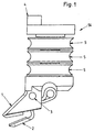
- Fig. 1 shows a side view of a drag loop gripper module 54, which as a gripper or Retainer acts and is used in the present invention.
- the Drag circuit gripper module 54 comprises a fixed upper jaw 1 and a movable one lower jaw 2.
- the lower jaw 2 is in an open position shown.
- the lower jaw 2 is from an open position to a closed one Position movable by rotation about a pivot pin 3.
- the gripper module 54 also includes Guide rollers 5, which rotate independently of one another.
- a rotation regulating insert 4 is used used to rotate the gripper module 54 in a desired operative orientation.
- FIG. 2 is a three-dimensional view of the rear of the gripper module 54.
- the lower jaw 2 is in a closed position.
- Fig. 2 shows one Gripper opening pin 6 for the gripper module 54, the gripper opening pin 6 with the lower jaw 2 is connected and rotates about the pivot pin 3. Rotation of the gripper opening pin 6 upwards, the lower jaw 2 rotates about the pivot pin 3 below, whereby the lower jaw 2 is moved into the open position. rotation the gripper opening pin 6 down, the lower jaw 2 rotates about the pivot pin 3 upwards, whereby the lower jaw 2 is moved into the closed position.
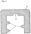
- Fig. 3 is a sectional view of the gripper module 54.
- a spring 10 presses on the end of the lower jaw 2, which surrounds the opening pin 6, whereby the lower The jaw 2 is preloaded into a closed position, as shown in Fig. 3.
- a preload force therefore holds a signature in the gripper module 54 between the upper ones Jaw 1 and lower jaw 2.
- Each of the guide rollers 5 is on a bearing 9, the is shown schematically in Fig. 3 attached, so that each of the guide rollers 5 itself can freely rotate around the central module center line 55.
- the rotation regulating insert 4 rotates freely around a hub 7 on top of the gripper module 54.
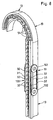
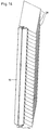
- the Track 13 includes raised sections 14 on the inside, which are in the grooves in the Move idlers 5 to thereby clamp the gripper modules 54 in the track 13.
- a Indentation 15 in track 13 regulates the active orientation of gripper module 54
- the gripper module 54 thus moves freely in the track 13 and can either be driven along the track by gravity or by a any known device for transmitting kinetic energy to a free device moving along a track, e.g. driven sprockets or chains etc. that are placed at spaced locations along the length of the track 13.
- FIG. 7 shows a series of gripper modules 54 which move in the direction 56.
- track 13 is omitted for clarity, but it is assumed that the modules 54 in FIG. 7 all move along a track 13.
- a row of Signatures, e.g. Arches 28 are transported in one direction so that they follow the path of the Cut gripper modules 54 at an intersection 100.
- the gripper modules 54 Before reaching the intersection 100, the gripper modules 54 have their lower jaws 2 in contact with the upper one Clamping jaw 1, whereby the gripper module is brought into the closed position (see uppermost gripper module 54 in FIG. 7). While the gripper modules Approach intersection 100, the gripper opening pin 6 by a gripper opening cam 300, which is shown in broken lines in FIG. 7, to the left pressed.
- the lower jaw 2 is therefore kept open until a front edge 101 the signature in the space between the lower jaw 2 and the upper Clamping jaw 1 of a gripper module 54 arrives (see bottom gripper module in FIG. 7). After the leading edge 101 of a signature 28 between the lower jaw 2 and the upper jaw 1 has reached, the gripper opening pin 6 moves on the gripper opening cam 300 over, and the lower jaw 2 closes due to the Biasing force of the spring 10 against the upper jaw 1, whereby the signature 28 is held in the gripper module 54.
- FIG. 8 shows gripper modules 54, which are located along tracks 13 at the intersection 100 move past.
- the signatures 28 are not shown in FIG. 8.
- a short section of chain 31 moves on both sides of gripper modules 54 Intersection.
- the chains 31 are engaged around chain sprockets 102 and move in the same direction and at the same speed as the gripper modules 54.
- Register pins 32 on the chains 31 are aligned with the gripper modules 54.
- the Register pins 32 hold the leading edges 101 of the signatures 28 until the gripper modules 54 are closed on the signatures 28.
- the way in which the leading edges 101 of the signatures 28 inserted into the register pins 32 and between the jaws 1, 2 will be described below with reference to FIG. 9.
- FIG. 9 shows conveyor belts 34, 103 which show the signatures 28 at the intersection 100 transport.
- the signatures 28 arrive at the entry point 35 between the bands 34, 103 and are carried between the bands 34, 103 until they reach the register pins 32 touch, and are then pulled into the gripper modules 54 at the intersection 100 and seized by these.
- Motors 104 can drive the conveyor belts 103 while Motors 105 can drive the conveyor belts 34.
- Fig. 10 shows the manner in which the gripper modules 54 are redirected to replacement paths can be.
- the gripper module 54 in question is guided along a branch path 107.
- the Gripper modules move in a common area 38 along a path 56, until they reach a redirection point 61.
- the left side 37 and the right side 41 of the Tracks 57, 58 hold the gripper modules 54 on both sides in the common area 38.
- the right lane 58 deviates from the straight path of the left Lane 57 off.
- Track page 59 becomes the left side of branch path 107
- track side 60 becomes the right side of main path 106.
- the Gripper modules 54 are not held by the track sides 57, 58 alone.
- Gripper modules 54, which are to be diverted along the branch path 107 are driven by a drive element 39 held along the track side 58 until it both from the track side 58 and from the Track page 59 are recorded.
- gripper modules 54 are the main path 106 are to be diverted along, along the track side 57 by a drive element 108 held until they are held by both the track side 57 and the track side 60.
- the drive elements 39, 108 are preferably in the form of a band or a chain run and are driven around sprockets or pulleys and by carried this.
- Each segment of the drive elements 39, 108, with one side of a Gripper module 54 is engaged, comprises a releasable gripping element 201, which in FIG. 10 is shown schematically, with a gripping element for each side of the gripper module 54 201 is provided.
- Detachable gripping elements 201 can be in the form of electromagnets be executed, or any known clinker mechanism for detecting and holding one Be side of a gripper module 54 which is in contact with drive elements 39, 108.
- a Upstream sensor is used to scan each gripper module 54 uses and determines whether the respective gripper module 54 holds a single signature 28 or is missing or duplicated.
- a releasable gripping element 201 actuated on the drive element 108 to grip the gripper module 54, while the corresponding releasable gripping element 201 on the drive element 39 is not actuated.
- the latter case becomes a releasable gripping element 201 on the drive element 39 for gripping of the gripper module 54 is actuated, while the corresponding releasable gripping element 201 on Drive element 109 is not actuated.
- the gripper modules 54 are through the releasable gripping elements 201 on one of the drive elements 39, 108 separated, which each gripper module 54 either the main path 106 or the branch path 107 steer down.
- 11 shows a series of signatures 28 that are generated by a series of gripper modules 54 are transported along the main path 106. 11 also shows individual signatures 28 ', which are transported along the branch path 107 by gripper modules 54'. How 11, the signatures 28 'redirected onto the branch path 107 are Duplications, assuming that an empty one is missing Gripper module 54 'without signature 28 can be deflected along the branch path 107 has been. There will initially be gaps in the queue along the main path 106 which correspond to the deflection of gripper modules 54 'down the branch path 107. This Gaps in the queue behind the drive element 39 are eliminated after the Gripper modules 54 are released and can move freely along the track 13. This free movement enables the formation of a queue of gripper modules 54, which move to positions directly next to each other (see Fig. 14), whereby ensures that the collator is a complete queue individual signatures is supplied.
- FIG. 14 shows a queue of signatures 28 which are passed through the diversion point 61 and were guided along the main path 106 and due to the free movement of the Gripper modules 54 have formed a new queue in track 13.
- the signature queue includes a series of signatures 28, all of which none Have signature errors, are all in line with no gaps, and all can be guided one after the other into a collating device to thereby to form a complete bundle.
- the gripper modules 54, which hold the signatures 28, are guided along a straight section of the track 13, which acts as a snake Track acts.
- a collating device which is the method and of the device of the present invention, a number of the above described track and gripper systems, one for each signature included in a Bundle to be collated.
- the device of the present invention can be configured to continue Signatures are added to the queue while the feed jam is cleared becomes.
- the gripper conveyor system can either Detect a jam or when the operator clears a jam Allow signatures to be queued at a speed that is faster than the speed at which the collator makes signatures from the snake.
- the separation process fills the Snake up at a speed higher than that at which signatures are extracted
- the snake can be removed so that the snake stops and breaks in the Snake can "catch up" due to the traffic jam and operator intervention To clear the jam.
- This feature enables a buffer of Claws in the signature queue, which fills up the queue while clearing jams or after the traffic jams have been cleared.
- the traffic jam during the process of delivering signatures from the queue to one Gathering machine can be eliminated without the gathering process for Clearing the jam must be stopped.
- a second method of handling Traffic jams consist of providing several separation stations, which are the same Feed the singling line, i.e.
- a barrier or separator at the point where the plurality of tracks 13 meets the single track 13 affects the device in such a way that the individual track 13 is only fed by one of the many tracks, which open into the single track 13. This procedure enables one to be activated redundant feed track and loading the signal door queue when the Main feed track jams and must be stopped to clear the jam.
Landscapes
- Engineering & Computer Science (AREA)
- Mechanical Engineering (AREA)
- Collation Of Sheets And Webs (AREA)
- Feeding Of Articles By Means Other Than Belts Or Rollers (AREA)
Abstract
Description
- Fig. 1
- eine Seitenansicht eines erfindungsgemäßen Schleppkreis-Greifermoduls;
- Fig. 2
- eine dreidimensionale Ansicht des Greifermoduls der Fig. 1;
- Fig. 3
- eine Schnittansicht des Greifermoduls der Fig. 1;
- Fig. 4
- eine Schnittansicht einer Spur, in der sich das Greifermodul bewegt;
- Fig. 5
- eine Schnittansicht eines Greifermoduls, das in die Spur der Fig. 4 eingesetzt ist;
- Fig. 6
- eine dreidimensionale Ansicht eines sich in einer Spur bewegenden Greifermoduls;
- Fig. 7
- eine Seitenansicht einer Reihe von Greifermodulen, die eine Reihe von Signaturen erfassen;
- Fig. 8
- eine dreidimensionale Ansicht einer Reihe von Greifer, die sich in einer Spur an einer Gabelungsstelle vorbei bewegen;
- Fig. 9
- eine dreidimensionale Ansicht von Transportbändern, die Signaturen zu der Gabelungsstelle transportieren;
- Fig. 10
- eine Unteransicht von Greifermodulen, die sich auf sich ablösenden Pfaden bewegen;
- Fig. 11
- eine Unteransicht von Signaturen, die in Greifermodulen getragen werden, die sich auf sich ablösenden Pfaden bewegen;
- Fig. 12
- eine Detail-Unteransicht einer Umleitung für die Greifermodule;
- Fig. 13
- eine Detail-Unteransicht von Greifermodulen, die umgeleitet werden;
- Fig. 14
- eine dreidimensionale Ansicht einer Signaturenschlange.
- 1
- obere Klemmbacke
- 2
- untere Klemmbacke
- 3
- Drehstift
- 4
- Drehungs-Reguliereinsatz
- 5
- Leitrolle
- 6
- Greifer-Öffnungsstift
- 7
- Nabe
- 9
- Lager
- 10
- Feder
- 13
- Spur
- 14
- erhöhter Abschnitt
- 15
- Vertiefung
- 28
- Signatur
- 31
- Kette
- 32
- Registerstifte
- 34
- Transportband
- 35
- Einziehpunkt
- 37
- linke Seite
- 38
- gemeinsamer Bereich
- 39
- Antriebselement
- 41
- rechte Seite
- 54
- Greifermodul
- 55
- Leitmodul-Mittellinie
- 56
- Richtung/Pfad
- 57
- linke Spur
- 58
- rechte Spur
- 59
- Spurseite
- 60
- Spurseite
- 61
- Umleitungsstelle
- 100
- Schnittpunkt
- 101
- Vorderkante
- 102
- Kettenzahnräder
- 103
- Transportband
- 104
- Motoren
- 105
- Motoren
- 106
- Hauptpfad
- 107
- Abzweigpfad
- 108
- Antriebselement
- 200
- Kettenzahnräder oder Riemenscheiben
- 201
- Greifelement
- 300
- Greifer-Öffnungsnocken
Claims (29)
- Vorrichtung zum Zuführen von Signaturen (28) in eine Zusammentragvorrichtung, welche die folgenden Merkmale umfaßt: mindestens eine Spur (13), wobei diese mindestens eine Spur (13) einen Umleitungsabschnitt (61) umfaßt, welcher wiederum einen Hauptpfad (106) und einen Abzweigpfad (107) umfaßt; eine Vielzahl von Greifern (54), wobei die Greifer (54) in der mindestens einen Spur (13) zur freien Bewegung in mindestens einem Abschnitt der mindestens einen Spur (13) befestigt sind, und mindestens ein Antriebselement (39, 108), wobei das mindestens eine Antriebselement (39, 108 jeden der Greifer (54) entweder entlang des Hauptpfades (106) oder entlang des Abzweigpfades (107) antreibt.
- Vorrichtung nach Anspruch 1,
dadurch gekennzeichnet,
daß jeder Greifer (54) zwei Klemmbacken (1, 2) umfaßt, und mindestens eine der Klemmbacken (1, 2) bezüglich der anderen Klemmbacke (1, 2) bewegbar ist. - Vorrichtung nach Anspruch 2,
dadurch gekennzeichnet,
daß mindestens eine bewegbare Klemmbacke (2) gegenüber der anderen Klemmbacke (1) vorbelastet ist. - Vorrichtung nach Anspruch 3, welche weiterhin folgende Merkmale umfaßt: eine Feder (10), wobei die Feder (10) die mindestens eine bewegbare Klemmbacke (2) vorbelastet.
- Vorrichtung nach Anspruch 1,
dadurch gekennzeichnet,
daß jeder Greifer (54) mindestens ein Lager (9) umfaßt, wobei das mindestens eine Lager (9) ein freies Bewegen des Greifers (54) in der mindestens einen Spur (13) ermöglicht. - Vorrichtung nach Anspruch 1,
dadurch gekennzeichnet,
daß jeder Greifer (54) mindestens eine Leitrolle (5) umfaßt, und die mindestens eine Spur (13) mindestens einen erhöhten Abschnitt (14) umfaßt, wobei die mindestens eine Leitrolle (5) jedes Greifers (54) mit dem mindestens einen erhöhten Abschnitt (14) der mindestens einen Spur (13) in Eingriff steht. - Vorrichtung nach Anspruch 1,
dadurch gekennzeichnet,
daß jeder Greifer (54) mindestens ein Drehungs-Regulierelement (4) umfaßt, und die mindestens eine Spur (13) mindestens eine Vertiefung (15) umfaßt, wobei das mindestens eine Drehungs-Regulierelement (4) jedes Greifers (54) in die mindestens eine Vertiefung (15) der mindestens einen Spur (13) eingreift, um dadurch die Drehausrichtung eines jeden Greifers (54) zu regulieren. - Vorrichtung nach Anspruch 1, welche weiterhin folgende Merkmale umfaßt: einen Schnittpunkt (100) auf der mindestens einen Spur (13), wobei der Schnittpunkt (100) eine Vielzahl von Registerstiften (32) umfaßt, und die Registerstifte (32) eine Kante einer Signatur halten, während diese in einen der Greifer (54) eingeführt wird.
- Vorrichtung nach Anspruch 1, welche weiterhin die folgenden Merkmale umfaßt: mindestens ein Transportband (34), wobei das mindestens eine Transportband (34) Signaturen (28) in die Greifer (54) zuführt.
- Vorrichtung nach Anspruch 9,
dadurch gekennzeichnet,
daß das mindestens eine Transportband (34) zwei Transportbänder umfaßt, wobei eine Signatur (28) zwischen den beiden Transportbändern transportiert wird. - Vorrichtung nach Anspruch 1,
dadurch gekennzeichnet,
daß das mindestens eine Antriebselement (108) ein Hauptpfad-Antriebselement zum Antreiben von Greifern (54) entlang des Hauptpfades (106) und ein Abzweigpfad-Antriebselement (39) zum Antreiben von Greifern (54) entlang des Abzweigpfades (107) umfaßt. - Vorrichtung nach Anspruch 11,
dadurch gekennzeichnet,
daß das Hauptpfad-Antriebselement (108) und das Abzweigpfad-Antriebselement (39) Bänder oder Ketten umfassen. - Vorrichtung nach Anspruch 11,
dadurch gekennzeichnet,
daß das Hauptpfad-Antriebselement (108) und das Abzweigpfad-Antriebselement (39) lösbare Greifelemente (201) umfassen. - Vorrichtung nach Anspruch 13,
dadurch gekennzeichnet,
daß die lösbaren Greifelemente (201) Elektromagnete umfassen. - Vorrichtung nach Anspruch 1, welche weiterhin die folgenden Merkmale umfaßt: eine schlangebildende Spur (13), die sich hinter dem Hauptpfad (106) befindet, wobei sich die Greifer (54) frei in der schlangebildenden Spur (13) bewegen.
- Vorrichtung nach Anspruch 1, welche weiterhin die folgenden Merkmale umfaßt: eine Vielzahl von Spuren (13), wobei die Greifer (54) in einer der Vielzahl von Spuren (13) zum freien Bewegen in mindestens einem Abschnitt der einen der Vielzahl von Spuren (13) befestigt sind.
- Vorrichtung nach Anspruch 1,
dadurch gekennzeichnet,
daß die Greifer (54) der Zusammentragvorrichtung Signaturen (28) zuführen. - Vorrichtung nach Anspruch 1, welche weiterhin die folgenden Merkmale umfaßt: mindestens eine schlangebildende Spur (13) und eine Vielzahl von Zuführspuren, wobei jede der Vielzahl von Zuführspuren mit der mindestens einen schlangebildenden (13) Spur zusammengeführt wird, um dadurch Greifer (54) aus den Zuführspuren der schlangebildenden Spur (13) zuzuführen.
- Vorrichtung nach Anspruch 2, welche weiterhin die folgenden Merkmale umfaßt: einen Greifer-Öffnungsnocken (6), wobei die mindestens eine bewegbare Klemmbacke (2) den Greifer-Öffnungsnocken (6) berührt, und der Greifer-Öffnungsnocken (6) die mindestens eine bewegbare Klemmbacke (2) bezüglich der anderen Klemmbacke (1) bewegt.
- Verfahren zum Zuführen von Signaturen (28) in eine Zusammentragvorrichtung, welches die folgenden Schritte umfaßt:
Vorsehen von mindestens einer Spur (13), die einen Umleitungsabschnitt (61) umfaßt, wobei der Umleitungsabschnitt (61) einen Hauptpfad (106) und einen Abzweigpfad (107) umfaßt; Vorsehen einer Vielzahl von Greifern (54), die in der mindestens einen Spur (13) zur freien Bewegung in mindestens einem Teil der mindestens einen Spur (13) befestigt sind; Zuführen von Signaturen (27) in die Vielzahl von Greifern (54); Ergreifen von Signaturen (28) in mindestens einigen der Vielzahl von Greifern (54); Umlenken von Greifern (54), die eine einzelne Signatur (28) halten, entlang des Hauptpfades (106), und Umlenken von Greifern (54), die keine einzelne Signatur (28) halten, entlang des Abzweigpfades (107). - Verfahren nach Anspruch 20,
dadurch gekennzeichnet,
daß der Schritt des Ergreifens ein Greifen von Signaturen (28) zwischen Klemmbacken (1, 2) umfaßt, die bezüglich einander bewegbar sind. - Verfahren nach Anspruch 20, welches weiterhin folgenden Schritt umfaßt:
Regulieren der Drehposition eines jeden Greifers (54). - Verfahren nach Anspruch 20, welches weiterhin folgenden Schritt umfaßt:
Halten von Kanten (101) der Signaturen (28), während diese in die Greifer (54) geführt werden. - Verfahren nach Anspruch 20, welches weiterhin folgenden Schritt umfaßt:
Transportieren von Signaturen (28) zu den Greifern (54). - Verfahren nach Anspruch 24,
dadurch gekennzeichnet,
daß der Schritt des Transportierens den Transport der Signaturen (28) zwischen zwei Transportbändern (34, 103) umfaßt. - Verfahren nach Anspruch 20,
dadurch gekennzeichnet,
daß der Schritt des Umleitens von Greifern (54) entlang des Hauptpfades (106) das Antreiben von Greifern (54) unter Verwendung eines Hauptpfad-Antriebselements (108) umfaßt, und der Schritt des Umleitens von Greifern (54) entlang des Abzweigpfades (107) das Antreiben von Greifern (54) unter Verwendung eines Abzweigpfad-Antriebselements (39) umfaßt. - Verfahren nach Anspruch 26,
dadurch gekennzeichnet,
daß der Schritt des Antreibens von Greifern (54) unter Verwendung eines Hauptpfad-Antriebselements (108) lösbares Greifen der Greifer (54) umfaßt, und der Schritt des Antreibens von Greifern (54) unter Verwendung eines Abzweigpfad-Antriebselements (39) lösbares Greifen der Greifer (54) umfaßt. - Verfahren nach Anspruch 27,
dadurch gekennzeichnet,
daß der Schritt des lösbaren Greifens der Greifer (54) lösbares Greifen der Greifer (54) unter Verwendung von Elektromagneten umfaßt. - Verfahren nach Anspruch 20, welches weiterhin folgenden Schritt umfaßt:
Transportieren von Greifern (54) zu einer schlangebildenden Spur (13) hinter dem Hauptpfad (106), wobei sich die Greifer (54) frei in der schlangebildenden Spur (13) bewegen.
Applications Claiming Priority (2)
| Application Number | Priority Date | Filing Date | Title |
|---|---|---|---|
| US08/946,691 US6007064A (en) | 1997-10-08 | 1997-10-08 | Singularizer with magnetically diverted gripper conveyor and method of singularizing |
| US946691 | 1997-10-08 |
Publications (2)
| Publication Number | Publication Date |
|---|---|
| EP0908406A1 true EP0908406A1 (de) | 1999-04-14 |
| EP0908406B1 EP0908406B1 (de) | 2002-11-27 |
Family
ID=25484819
Family Applications (1)
| Application Number | Title | Priority Date | Filing Date |
|---|---|---|---|
| EP98117877A Expired - Lifetime EP0908406B1 (de) | 1997-10-08 | 1998-09-21 | Vorrichtung und Verfahren zum Fördern und Ablenken von individuell gehaltenen Produkten |
Country Status (3)
| Country | Link |
|---|---|
| US (1) | US6007064A (de) |
| EP (1) | EP0908406B1 (de) |
| DE (1) | DE59806424D1 (de) |
Cited By (1)
| Publication number | Priority date | Publication date | Assignee | Title |
|---|---|---|---|---|
| US6581752B2 (en) | 2000-05-17 | 2003-06-24 | Ferag Ag | Method and device for splitting-up a stream of piece goods |
Families Citing this family (9)
| Publication number | Priority date | Publication date | Assignee | Title |
|---|---|---|---|---|
| JP4030071B2 (ja) * | 1996-12-13 | 2008-01-09 | フェラーク アーゲー | 個々に保持される製品搬送のための方法及び装置 |
| CA2309037C (en) * | 1997-12-23 | 2008-06-03 | Ferag Ag | Conveying means which can be rail-guided and a guiding rail for guiding said conveying means |
| US6044958A (en) * | 1998-02-03 | 2000-04-04 | Heidelberger Druckmaschinen Ag | Sheet conveyance device with diverter for modules |
| US6386816B1 (en) | 1999-08-30 | 2002-05-14 | Tokyo Kikai Seisakusho, Ltd. | Printed matter transport device |
| AU2005257998B2 (en) * | 2004-06-18 | 2010-11-25 | Terje Gulbrandsen | Sheet handling apparatus |
| US9302875B2 (en) | 2011-02-22 | 2016-04-05 | Goss International Americas, Inc. | Method and apparatus for diverting signatures in a folder |
| AU2014384162B2 (en) * | 2014-02-27 | 2020-02-06 | Nanopix Integrated Software Solutions Private Limited | An improved machine for grading small sized irregular objects and a process thereof |
| DE202017106670U1 (de) * | 2017-11-03 | 2019-02-05 | Dematic Logistics Gmbh | Kettenglied, Förderkette und Fördervorrichtung |
| CN109353765B (zh) * | 2018-11-27 | 2023-05-30 | 太仓朗盛金属制品有限公司 | 一种上下楼梯传动系统及其工作方法 |
Citations (4)
| Publication number | Priority date | Publication date | Assignee | Title |
|---|---|---|---|---|
| DE1153383B (de) * | 1959-12-23 | 1963-08-29 | Ferag Fehr & Reist A G | Einrichtung zum Ablegen der bogenfoermigen Produkte einer Rotationsdruckmaschine |
| WO1998003420A1 (de) * | 1996-07-19 | 1998-01-29 | Ferag Ag | Förderanlage |
| EP0827929A1 (de) * | 1996-09-09 | 1998-03-11 | Heidelberger Druckmaschinen Aktiengesellschaft | Vorrichtung zum Transportieren flacher Produkte zu Weiterverarbeitungseinrichtungen oder Auslagestationen |
| WO1998025845A1 (de) * | 1996-12-13 | 1998-06-18 | Ferag Ag | Verfahren und anordnung zum fördern von individuell gehaltenen produkten |
Family Cites Families (4)
| Publication number | Priority date | Publication date | Assignee | Title |
|---|---|---|---|---|
| US3807314A (en) * | 1973-03-30 | 1974-04-30 | Us Army | Magnetic trolley conveyor system |
| CH618398A5 (de) * | 1977-06-06 | 1980-07-31 | Ferag Ag | |
| US5072822A (en) * | 1990-06-20 | 1991-12-17 | Fabri-Check, Inc. | Article sorting system |
| US5465952A (en) * | 1993-02-17 | 1995-11-14 | Ferag Ag | Gripper for a conveying device for conveying single-sheet or multiple-sheet printed products |
-
1997
- 1997-10-08 US US08/946,691 patent/US6007064A/en not_active Expired - Lifetime
-
1998
- 1998-09-21 DE DE59806424T patent/DE59806424D1/de not_active Expired - Lifetime
- 1998-09-21 EP EP98117877A patent/EP0908406B1/de not_active Expired - Lifetime
Patent Citations (4)
| Publication number | Priority date | Publication date | Assignee | Title |
|---|---|---|---|---|
| DE1153383B (de) * | 1959-12-23 | 1963-08-29 | Ferag Fehr & Reist A G | Einrichtung zum Ablegen der bogenfoermigen Produkte einer Rotationsdruckmaschine |
| WO1998003420A1 (de) * | 1996-07-19 | 1998-01-29 | Ferag Ag | Förderanlage |
| EP0827929A1 (de) * | 1996-09-09 | 1998-03-11 | Heidelberger Druckmaschinen Aktiengesellschaft | Vorrichtung zum Transportieren flacher Produkte zu Weiterverarbeitungseinrichtungen oder Auslagestationen |
| WO1998025845A1 (de) * | 1996-12-13 | 1998-06-18 | Ferag Ag | Verfahren und anordnung zum fördern von individuell gehaltenen produkten |
Cited By (1)
| Publication number | Priority date | Publication date | Assignee | Title |
|---|---|---|---|---|
| US6581752B2 (en) | 2000-05-17 | 2003-06-24 | Ferag Ag | Method and device for splitting-up a stream of piece goods |
Also Published As
| Publication number | Publication date |
|---|---|
| EP0908406B1 (de) | 2002-11-27 |
| US6007064A (en) | 1999-12-28 |
| DE59806424D1 (de) | 2003-01-09 |
Similar Documents
| Publication | Publication Date | Title |
|---|---|---|
| EP0827929B1 (de) | Vorrichtung zum Transportieren flacher Produkte zu Weiterverarbeitungseinrichtungen oder Auslagestationen | |
| DE2410993A1 (de) | Zusammentragegeraet fuer bogen- und blattmaterial, insbesondere fuer signaturen | |
| EP1232978A1 (de) | Fördereinrichtung zum Sammeln und Transportieren von auf einer ersten Förderkette rittlings aufgelegten Druckbogen | |
| DE102009001746A1 (de) | Vorrichtung zum Überführen von Produkten von einem Zufuhr- auf ein Abfuhrförderband mittels Greifern und Verfahren zum Betrieb der Vorrichtung | |
| DE3433497C2 (de) | ||
| EP0757960B1 (de) | Vorrichtung zum geordneten Transport von Packungen | |
| EP0908408B1 (de) | Vorrichtung und Verfahren für das kombinierte Zusammentragen und Binden von bogenförmigen Produkten | |
| DE3221001A1 (de) | Foerdervorrichtungen fuer zeitungen und dergleichen | |
| CH649972A5 (de) | Vorrichtung zum uebereinanderlegen von einzelnen flaechigen erzeugnissen, insbesondere druckprodukten. | |
| EP0908406B1 (de) | Vorrichtung und Verfahren zum Fördern und Ablenken von individuell gehaltenen Produkten | |
| EP1016603A2 (de) | Vorrichtung und Verfahren zur Zufuhr von Signaturen | |
| DE4333575A1 (de) | Verfahren und Vorrichtung zum Bilden und Versetzen von Stapeln aus bedruckten Blättern, insbesondere Belegen | |
| EP0754642B1 (de) | Verfahren und Vorrichtung zur Auslage bögenförmiger Produkte | |
| EP0897890B1 (de) | Verfahren und Vorrichtung zur Erstellung eines gedrehten Produktstromes mit einem Eckengreifer | |
| EP0659586B1 (de) | Verfahren zur Beschickung von zu Druckprodukten gesammelten, mehrblättrigen Druckbogen mit Beilagen | |
| EP0854105A1 (de) | Verfahren und Vorrichtung zum Verarbeiten von flächigen Druckereierzeugnissen, wie Zeitungen, Zeitschriften und Teilen hievon | |
| EP0514783B1 (de) | Vorrichtung zum Fördern von Papierbogenstapeln | |
| EP0765247B1 (de) | Verfahren und vorrichtung zum bearbeiten von druckereierzeugnissen | |
| CH669585A5 (de) | ||
| EP0806392B1 (de) | Verfahren zum Sammeln von Druckprodukten zu Druckerzeugnissen | |
| CH690434A5 (de) | Verfahren und Vorrichtung zum Zusammenbringen von Druckereierzeugnissen. | |
| DE2832660B2 (de) | Vorrichtung zum gruppenweisen Abteilen von geschuppt übereinanderliegend geförderten Werkstücken | |
| EP0970820A2 (de) | Transportvorrichtung | |
| DE2109468C2 (de) | Faltmaschine zum Umlegen der Laschen von Faltschachteln | |
| EP1072546A1 (de) | Förderanlage zum Zusammentragen und Bearbeiten von Druckbogen |
Legal Events
| Date | Code | Title | Description |
|---|---|---|---|
| PUAI | Public reference made under article 153(3) epc to a published international application that has entered the european phase |
Free format text: ORIGINAL CODE: 0009012 |
|
| 17P | Request for examination filed |
Effective date: 19980921 |
|
| AK | Designated contracting states |
Kind code of ref document: A1 Designated state(s): CH DE FR GB LI |
|
| AX | Request for extension of the european patent |
Free format text: AL;LT;LV;MK;RO;SI |
|
| AKX | Designation fees paid |
Free format text: CH DE FR GB LI |
|
| 17Q | First examination report despatched |
Effective date: 20010710 |
|
| GRAG | Despatch of communication of intention to grant |
Free format text: ORIGINAL CODE: EPIDOS AGRA |
|
| GRAG | Despatch of communication of intention to grant |
Free format text: ORIGINAL CODE: EPIDOS AGRA |
|
| GRAG | Despatch of communication of intention to grant |
Free format text: ORIGINAL CODE: EPIDOS AGRA |
|
| GRAH | Despatch of communication of intention to grant a patent |
Free format text: ORIGINAL CODE: EPIDOS IGRA |
|
| GRAH | Despatch of communication of intention to grant a patent |
Free format text: ORIGINAL CODE: EPIDOS IGRA |
|
| GRAA | (expected) grant |
Free format text: ORIGINAL CODE: 0009210 |
|
| AK | Designated contracting states |
Kind code of ref document: B1 Designated state(s): CH DE FR GB LI |
|
| PG25 | Lapsed in a contracting state [announced via postgrant information from national office to epo] |
Ref country code: GB Free format text: LAPSE BECAUSE OF FAILURE TO SUBMIT A TRANSLATION OF THE DESCRIPTION OR TO PAY THE FEE WITHIN THE PRESCRIBED TIME-LIMIT Effective date: 20021127 Ref country code: FR Free format text: LAPSE BECAUSE OF FAILURE TO SUBMIT A TRANSLATION OF THE DESCRIPTION OR TO PAY THE FEE WITHIN THE PRESCRIBED TIME-LIMIT Effective date: 20021127 |
|
| REG | Reference to a national code |
Ref country code: GB Ref legal event code: FG4D Free format text: NOT ENGLISH |
|
| REG | Reference to a national code |
Ref country code: CH Ref legal event code: EP |
|
| REF | Corresponds to: |
Ref document number: 59806424 Country of ref document: DE Date of ref document: 20030109 |
|
| GBV | Gb: ep patent (uk) treated as always having been void in accordance with gb section 77(7)/1977 [no translation filed] |
Effective date: 20021127 |
|
| EN | Fr: translation not filed | ||
| PLBE | No opposition filed within time limit |
Free format text: ORIGINAL CODE: 0009261 |
|
| STAA | Information on the status of an ep patent application or granted ep patent |
Free format text: STATUS: NO OPPOSITION FILED WITHIN TIME LIMIT |
|
| 26N | No opposition filed |
Effective date: 20030828 |
|
| PGFP | Annual fee paid to national office [announced via postgrant information from national office to epo] |
Ref country code: CH Payment date: 20100930 Year of fee payment: 13 |
|
| PGFP | Annual fee paid to national office [announced via postgrant information from national office to epo] |
Ref country code: DE Payment date: 20100929 Year of fee payment: 13 |
|
| REG | Reference to a national code |
Ref country code: CH Ref legal event code: PL |
|
| REG | Reference to a national code |
Ref country code: DE Ref legal event code: R119 Ref document number: 59806424 Country of ref document: DE Effective date: 20120403 |
|
| PG25 | Lapsed in a contracting state [announced via postgrant information from national office to epo] |
Ref country code: LI Free format text: LAPSE BECAUSE OF NON-PAYMENT OF DUE FEES Effective date: 20110930 Ref country code: CH Free format text: LAPSE BECAUSE OF NON-PAYMENT OF DUE FEES Effective date: 20110930 Ref country code: DE Free format text: LAPSE BECAUSE OF NON-PAYMENT OF DUE FEES Effective date: 20120403 |