EP0906856B2 - Frein à disque à étrier flottant - Google Patents
Frein à disque à étrier flottant Download PDFInfo
- Publication number
- EP0906856B2 EP0906856B2 EP98118564A EP98118564A EP0906856B2 EP 0906856 B2 EP0906856 B2 EP 0906856B2 EP 98118564 A EP98118564 A EP 98118564A EP 98118564 A EP98118564 A EP 98118564A EP 0906856 B2 EP0906856 B2 EP 0906856B2
- Authority
- EP
- European Patent Office
- Prior art keywords
- carrier
- brake
- disc
- sliding calliper
- reaction
- Prior art date
- Legal status (The legal status is an assumption and is not a legal conclusion. Google has not performed a legal analysis and makes no representation as to the accuracy of the status listed.)
- Expired - Lifetime
Links
- 238000006243 chemical reaction Methods 0.000 claims description 14
- 238000006073 displacement reaction Methods 0.000 claims description 5
- 230000004323 axial length Effects 0.000 claims description 3
- 238000009434 installation Methods 0.000 description 3
- 238000010276 construction Methods 0.000 description 2
- 230000008878 coupling Effects 0.000 description 2
- 238000010168 coupling process Methods 0.000 description 2
- 238000005859 coupling reaction Methods 0.000 description 2
Images

Classifications
-
- F—MECHANICAL ENGINEERING; LIGHTING; HEATING; WEAPONS; BLASTING
- F16—ENGINEERING ELEMENTS AND UNITS; GENERAL MEASURES FOR PRODUCING AND MAINTAINING EFFECTIVE FUNCTIONING OF MACHINES OR INSTALLATIONS; THERMAL INSULATION IN GENERAL
- F16D—COUPLINGS FOR TRANSMITTING ROTATION; CLUTCHES; BRAKES
- F16D55/00—Brakes with substantially-radial braking surfaces pressed together in axial direction, e.g. disc brakes
- F16D55/02—Brakes with substantially-radial braking surfaces pressed together in axial direction, e.g. disc brakes with axially-movable discs or pads pressed against axially-located rotating members
- F16D55/22—Brakes with substantially-radial braking surfaces pressed together in axial direction, e.g. disc brakes with axially-movable discs or pads pressed against axially-located rotating members by clamping an axially-located rotating disc between movable braking members, e.g. movable brake discs or brake pads
- F16D55/224—Brakes with substantially-radial braking surfaces pressed together in axial direction, e.g. disc brakes with axially-movable discs or pads pressed against axially-located rotating members by clamping an axially-located rotating disc between movable braking members, e.g. movable brake discs or brake pads with a common actuating member for the braking members
-
- B—PERFORMING OPERATIONS; TRANSPORTING
- B60—VEHICLES IN GENERAL
- B60T—VEHICLE BRAKE CONTROL SYSTEMS OR PARTS THEREOF; BRAKE CONTROL SYSTEMS OR PARTS THEREOF, IN GENERAL; ARRANGEMENT OF BRAKING ELEMENTS ON VEHICLES IN GENERAL; PORTABLE DEVICES FOR PREVENTING UNWANTED MOVEMENT OF VEHICLES; VEHICLE MODIFICATIONS TO FACILITATE COOLING OF BRAKES
- B60T1/00—Arrangements of braking elements, i.e. of those parts where braking effect occurs specially for vehicles
- B60T1/02—Arrangements of braking elements, i.e. of those parts where braking effect occurs specially for vehicles acting by retarding wheels
- B60T1/06—Arrangements of braking elements, i.e. of those parts where braking effect occurs specially for vehicles acting by retarding wheels acting otherwise than on tread, e.g. employing rim, drum, disc, or transmission or on double wheels
- B60T1/065—Arrangements of braking elements, i.e. of those parts where braking effect occurs specially for vehicles acting by retarding wheels acting otherwise than on tread, e.g. employing rim, drum, disc, or transmission or on double wheels employing disc
-
- F—MECHANICAL ENGINEERING; LIGHTING; HEATING; WEAPONS; BLASTING
- F16—ENGINEERING ELEMENTS AND UNITS; GENERAL MEASURES FOR PRODUCING AND MAINTAINING EFFECTIVE FUNCTIONING OF MACHINES OR INSTALLATIONS; THERMAL INSULATION IN GENERAL
- F16D—COUPLINGS FOR TRANSMITTING ROTATION; CLUTCHES; BRAKES
- F16D65/00—Parts or details
- F16D65/02—Braking members; Mounting thereof
- F16D65/12—Discs; Drums for disc brakes
-
- F—MECHANICAL ENGINEERING; LIGHTING; HEATING; WEAPONS; BLASTING
- F16—ENGINEERING ELEMENTS AND UNITS; GENERAL MEASURES FOR PRODUCING AND MAINTAINING EFFECTIVE FUNCTIONING OF MACHINES OR INSTALLATIONS; THERMAL INSULATION IN GENERAL
- F16D—COUPLINGS FOR TRANSMITTING ROTATION; CLUTCHES; BRAKES
- F16D55/00—Brakes with substantially-radial braking surfaces pressed together in axial direction, e.g. disc brakes
- F16D2055/0004—Parts or details of disc brakes
- F16D2055/0008—Brake supports
-
- F—MECHANICAL ENGINEERING; LIGHTING; HEATING; WEAPONS; BLASTING
- F16—ENGINEERING ELEMENTS AND UNITS; GENERAL MEASURES FOR PRODUCING AND MAINTAINING EFFECTIVE FUNCTIONING OF MACHINES OR INSTALLATIONS; THERMAL INSULATION IN GENERAL
- F16D—COUPLINGS FOR TRANSMITTING ROTATION; CLUTCHES; BRAKES
- F16D55/00—Brakes with substantially-radial braking surfaces pressed together in axial direction, e.g. disc brakes
- F16D2055/0004—Parts or details of disc brakes
- F16D2055/0016—Brake calipers
-
- F—MECHANICAL ENGINEERING; LIGHTING; HEATING; WEAPONS; BLASTING
- F16—ENGINEERING ELEMENTS AND UNITS; GENERAL MEASURES FOR PRODUCING AND MAINTAINING EFFECTIVE FUNCTIONING OF MACHINES OR INSTALLATIONS; THERMAL INSULATION IN GENERAL
- F16D—COUPLINGS FOR TRANSMITTING ROTATION; CLUTCHES; BRAKES
- F16D55/00—Brakes with substantially-radial braking surfaces pressed together in axial direction, e.g. disc brakes
- F16D2055/0004—Parts or details of disc brakes
- F16D2055/007—Pins holding the braking members
-
- F—MECHANICAL ENGINEERING; LIGHTING; HEATING; WEAPONS; BLASTING
- F16—ENGINEERING ELEMENTS AND UNITS; GENERAL MEASURES FOR PRODUCING AND MAINTAINING EFFECTIVE FUNCTIONING OF MACHINES OR INSTALLATIONS; THERMAL INSULATION IN GENERAL
- F16D—COUPLINGS FOR TRANSMITTING ROTATION; CLUTCHES; BRAKES
- F16D65/00—Parts or details
- F16D65/02—Braking members; Mounting thereof
- F16D2065/13—Parts or details of discs or drums
- F16D2065/1304—Structure
- F16D2065/1308—Structure one-part
-
- F—MECHANICAL ENGINEERING; LIGHTING; HEATING; WEAPONS; BLASTING
- F16—ENGINEERING ELEMENTS AND UNITS; GENERAL MEASURES FOR PRODUCING AND MAINTAINING EFFECTIVE FUNCTIONING OF MACHINES OR INSTALLATIONS; THERMAL INSULATION IN GENERAL
- F16D—COUPLINGS FOR TRANSMITTING ROTATION; CLUTCHES; BRAKES
- F16D65/00—Parts or details
- F16D65/02—Braking members; Mounting thereof
- F16D2065/13—Parts or details of discs or drums
- F16D2065/1304—Structure
- F16D2065/1328—Structure internal cavities, e.g. cooling channels
Definitions
- a sliding calliper disc brake for a land vehicle comprising a brake disc, a slide caliper, a carrier, an actuation side brake shoe, and a reaction side brake shoe, the carrier being held immovable with respect to the axle of the land vehicle, the brake disc being rotatably supported relative to the axle, and assembly / disassembly slidable with respect to the support in the direction of the axis, the sliding caliper has two legs, namely one which lies on the actuation side of the brake disc, and one which lies on the reaction side of the brake disc, the carrier extends axially from the actuation side to the reaction side of the brake disc carrier on the reaction side has a clear width, which is dimensioned so that the brake disc passes through during axial displacement for assembly / disassembly, and the carrier has guides on which the sliding caliper is slidably guided.
- the EP-A1-665 387 shows the construction of a sliding caliper disc brake and its attachment to an axle 1.
- the two saddle legs overlap U-shaped a brake disc 12 to press the both sides of the brake disc in guide shafts of a slide caliper support 14 mounted and supported brake shoes 17 against the brake disc.
- the slide carrier 14 in turn is bolted to a support flange 13 attached to the axle 1.
- the slide carrier for closed-surface guidance of the brake shoes is closed, ie that he frame-like the brake disc fully engages, see. also EP-A1-665 387 , Page 2, lines 55 and 56.
- the two known brakes described above are each commercial vehicle brakes, which accordingly have a comparatively large weight. Also, their individual components have a significant weight, which is why any additional step is considered disadvantageous.
- the DE-A-39 10 969 also shows a sliding caliper disc brake for cars. Also in this brake, arms 36 and 37 engage behind the brake disc. As further examples of brakes of this type are to call the US-A-5,297,659 , the DE-A-43 34 839 and the US-A-5,103,939 ,
- the DE-C2-29 19 548 shows a sliding calliper disc brake of the type mentioned.
- a reaction-side brake shoe grooves 33L and 33R, in the guide rails 30L and 30R of a carrier 11 engage.
- the reaction-side brake shoe is fixed in the radial direction on the carrier. If the brake disc to be changed, not only the sliding calliper must be lifted in the radial direction, but it must also be at least the reaction-side brake shoe are withdrawn in the axial direction of the carrier. Only then is the brake disc free so that it can be removed from the reaction side.
- the invention is based on the object, the sliding caliper disc brake after the DE-C2-29 19 548 in such a way that - even with regard to the very cramped installation conditions in wheel bearings - the amount of work for mounting / dismounting the brake disc is minimized.
- the sliding saddle and not the carrier for radial fixing of the reaction-side brake shoe is used. Therefore, no separate steps are required to dismantle the reaction-side brake shoe. Rather, the lifting of the sliding caliper - and thus the brake shoe fixed thereto - from the carrier to the brake disc for assembly / disassembly of the reaction side exposes sufficient.
- the carrier has two arms which extend axially from the actuation side to the reaction side and on its brake disc facing side first support surfaces for sliding guidance and support of the sliding saddle, and that the sliding rests with an outer contour on the support surfaces.
- the two arms of the wearer cooperate with the sliding saddle so that they can absorb the braking forces (at least in part).
- the reaction-side brake shoe will not shift in the axial direction with respect to the sliding caliper during braking.
- the reaction-side brake shoe therefore preferably supports in the tangential direction on the sliding saddle according to the invention.
- reaction-side and the actuation-side brake shoes are simply "plugged” into the cut-out, which makes their assembly / disassembly particularly easy.
- boundaries of the cutout serve as second support surfaces for the reaction-side brake shoe.
- the cutout and thus the support of the reaction-side brake shoe in the radial direction is open.
- the cutout also receives the operating side brake shoe, and the third support surfaces will have a radially open configuration.
- a retaining device is preferably provided which fixes the actuating-side brake shoe and the reaction-side brake shoe in the radial direction on the sliding saddle. This only one component must be solved to release both brake shoes.
- the sliding caliper disc brake on a shoulder on the sliding caliper or on the carrier which engages behind a corresponding contour on the carrier or on the sliding caliper and thereby locks the sliding caliper in the radial direction on the carrier, wherein the axial length of the neck or the Contour is such that the sliding caliper can be unlocked by axial displacement.
- Such a lock which should advantageously be provided at least on the brake disk inlet side, serves to guide the sliding saddle when re-attachment to the carrier.
- a particularly simple way of locking the sliding caliper on the carrier is achieved, for example in accordance with a bayonet closure.
- the guides according to the invention are preferably arranged on the approach or the contour.
- the carrier may be permanently connected to the axle. But it can also be releasably attached to the axle.
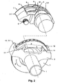
- FIGS. 1 and 2 show an axis 1 with a rigidly secured thereto carrier 2 and a sliding caliper 3, to the axial guide along the brake axis attached to the carrier guide pins 4 are used.
- the sliding saddle 3 is U-shaped, with an actuation side Saddle leg 5 carries a tension and acts against an operating side brake shoe 8.
- a brake disc 7 is mounted with a diameter D, the direction of rotation R is indicated by an arrow.
- both brake shoes 8, 9 are held by means of a releasable from the sliding saddle 3 holding means 10 such that they are fixed in the axial direction of the brake disc 7 movable, but with respect to other directions of the said holding means 10.
- the carrier 2 has on the actuation side two arms with supporting surfaces 11 which do not extend beyond the outer contour of the brake disk 7 in the radial direction.
- the distance A of the support surfaces 11 corresponds to the width of the actuation side brake shoe 8.
- the support surfaces are used for lateral support of the brake shoe 8 and thus to initiate the braking forces in the carrier 2.
- the reaction side extending in the radial direction two arms with support surfaces 12.
- the two arms are - seen in axial projection - arranged outside the brake disc contour.
- the distance B of the support surfaces from each other corresponds to the width C of the reaction-side saddle leg 6.
- the support surfaces in turn serve to initiate braking forces in the carrier 2, which are transmitted from the reaction-side brake shoe 9 on the sliding caliper 3.
- the reaction-side brake shoe 9 can transmit the braking forces to the sliding caliper 3, it is laterally supported on the sliding caliper 3.
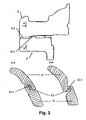
- the support surfaces 3.3 are formed by boundaries of the section 3.1.
- the section 3.1 has a width E, which corresponds to the width of the reaction-side brake shoe 9.
- an axial guidance of the carrier 2 in the area of the reaction-side support surface 12.1 overlaps a region 3.2 of the reaction-side saddle leg 6.
- the overlapping sections of the reaction-side saddle leg 6 on the one hand and the carrier 2 On the other hand, in its axial length are dimensioned such that the sliding saddle 3 can be locked or unlocked by axial displacement relative to the carrier 2.
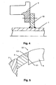
- Fig. 4 shows an embodiment in which the carrier 2 is releasably secured to a welded to the axis 1 flange 13.
- screws can be used, for example.
- the reaction-side free access to the brake disk 7 can be realized with only a few work steps. Nevertheless, a uniform guidance of the sliding caliper 3 and the brake shoes 8, 9 with respect to the carrier 2 is ensured.
- the dismantling is carried out as follows: After the wheel rim, the wheel hub, etc. have been removed from the axis 1 in a conventional manner, the guide pin 4 are first released from the carrier 2 to remove the brake disc 7. Thereafter, the sliding calliper 3 with the brake shoes 8, 9 fastened thereto by the holding means 10 can be raised radially from the carrier 2 in a single step over the diameter D of the brake disk 7. If, in addition, there is a coupling according to FIG.
- the sliding saddle 3 must first be displaced in the axial direction until the locking in the radial direction is released. In order to allow the axial displacement of the sliding saddle 3, space must be created in the interior of the sliding saddle 3 accordingly.
- the brake shoes in the axial direction
- the removal takes place from the carrier 2 as previously described. Due to the now freely accessible opening area between the support surfaces 12, the brake disk 7 can be deducted from the axle without further part removal.
Landscapes
- Engineering & Computer Science (AREA)
- General Engineering & Computer Science (AREA)
- Mechanical Engineering (AREA)
- Transportation (AREA)
- Braking Arrangements (AREA)
Claims (9)
- Frein à disque à étrier flottant destiné à un véhicule routier, comportant:un disque de frein (7),un étrier flottant (3),un support (2),une mâchoire de frein (8) du côté de l'actionnement, etune mâchoire de frein (9) du côté de la réaction, dans lequel:caractérisé en ce que :le support (2) est retenu en fixe par rapport à un axe (1) du véhicule routier,le disque de frein (7) est retenu en rotation par rapport à l'axe (1), et peut être déplacé en direction de l'axe (1) pour le montage / démontage du support (2),l'étrier flottant (3) comporte deux branches (5, 6), à savoir une branche (5) qui est située du côté de l'actionnement du disque de frein (7), et une branche (6) qui est située du côté de la réaction du disque de frein (7),l'étrier flottant (3) comporte une découpe (3.1) ouverte dans la direction radiale, destinée à la réception de la mâchoire de frein (8, 9) située du côté de la réaction et celle située du côté de l'actionnement,le support (2) s'étend axialement du côté de l'actionnement vers le côté de la réaction du disque de frein (7),le support (2) présente du côté de la réaction une largeur utile qui est dimensionnée de telle sorte que, lors de la translation axiale pour le montage / démontage, le disque de frein (7) passe à travers,le support (2) comporte des guidages (4), sur lesquels l'étrier flottant (3) est guidé de façon flottante, etla mâchoire de frein (9) située du côté de la réaction est fixée sur l'étrier flottant (3) dans la direction radiale, et peut être retirée du support (2) avec l'étrier flottant (3) dans la direction radiale en étant soulevée au-dessus de la périphérie extérieure du disque de frein (7),la mâchoire de frein (8) située du côté de l'actionnement prend appui de manière flottante sur des troisièmes surfaces d'appui (11) du support (2).
- Frein à disque à étrier flottant selon la revendication 1, caractérisé en ce que:le support (2) comporte deux bras qui s'étendent axialement du côté de l'actionnement vers le côté de la réaction, et qui comportent de leur côté orienté vers le disque de frein des premières surfaces d'appui (12) destinées au guidage et à l'appui flottants de l'étrier flottant (3), eten ce que l'étrier flottant (3) prend appui sur les surfaces d'appui (12) par son contour extérieur (3.2).
- Frein à disque à étrier flottant selon la revendication 1 ou 2, caractérisé en ce que la mâchoire de frein (9) située du côté de la réaction prend appui sur l'étrier flottant (3) dans la direction tangentielle.
- Frein à disque à étrier flottant selon l'une quelconque des revendications précédentes, caractérisé en ce que des délimitations (3.3) de la découpe (3.1) servent de secondes surfaces d'appui pour la mâchoire de frein (9) située du côté de la réaction.
- Frein à disque à étrier flottant selon l'une quelconque des revendications précédentes, caractérisé en ce qu'un dispositif de retenue (10) immobilise dans la direction radiale la mâchoire de frein (8) située du côté de l'actionnement et la mâchoire de frein (9) située du côté de la réaction sur l'étrier flottant (3).
- Frein à disque à étrier flottant selon l'une quelconque des revendications précédentes, caractérisé par un épaulement (12.1) prévu sur l'étrier flottant (3) ou sur le support (2), qui passe derrière un contour (3.2) correspondant du support (2) ou de l'étrier flottant (3), et qui verrouille de ce fait l'étrier flottant (3) sur le support dans la direction radiale, la longueur axiale de l'épaulement (12.1) ou du contour (3.2) étant telle que l'étrier flottant (3) puisse être déverrouillé par une translation axiale.
- Frein à disque à étrier flottant selon la revendication 6, caractérisé en ce que les guidages (12) sont disposés sur l'épaulement (12.1) ou sur le contour.
- Frein à disque à étrier flottant selon l'une quelconque des revendications précédentes, caractérisé en ce que le support (2) est relié de façon inamovible à l'axe (1).
- Frein à disque à étrier flottant selon l'une quelconque des revendications 1 à 7, caractérisé en ce que le support (2) est fixé de façon amovible sur l'axe (1).
Applications Claiming Priority (2)
| Application Number | Priority Date | Filing Date | Title |
|---|---|---|---|
| DE19743538A DE19743538A1 (de) | 1997-10-01 | 1997-10-01 | Gleitsattel-Scheibenbremse |
| DE19743538 | 1997-10-01 |
Publications (4)
| Publication Number | Publication Date |
|---|---|
| EP0906856A2 EP0906856A2 (fr) | 1999-04-07 |
| EP0906856A3 EP0906856A3 (fr) | 2001-11-07 |
| EP0906856B1 EP0906856B1 (fr) | 2003-07-30 |
| EP0906856B2 true EP0906856B2 (fr) | 2007-08-22 |
Family
ID=7844372
Family Applications (1)
| Application Number | Title | Priority Date | Filing Date |
|---|---|---|---|
| EP98118564A Expired - Lifetime EP0906856B2 (fr) | 1997-10-01 | 1998-10-01 | Frein à disque à étrier flottant |
Country Status (2)
| Country | Link |
|---|---|
| EP (1) | EP0906856B2 (fr) |
| DE (2) | DE19743538A1 (fr) |
Families Citing this family (12)
| Publication number | Priority date | Publication date | Assignee | Title |
|---|---|---|---|---|
| DE19823034C1 (de) * | 1998-05-22 | 1999-12-02 | Wabco Perrot Bremsen Gmbh | Scheibenbremse für ein Landfahrzeug |
| DE19857074B4 (de) * | 1998-12-10 | 2009-08-06 | Knorr-Bremse Systeme für Nutzfahrzeuge GmbH | Pneumatische Scheibenbremse und Bremsträger |
| US6820884B2 (en) | 2001-08-29 | 2004-11-23 | Meritor Heavy Vehicle Braking Systems | Integrated axle adaptor and spring seat for a vehicle suspension system |
| US20030042082A1 (en) * | 2001-08-29 | 2003-03-06 | Mccann Denis John | Vehicle axle assembly having a brake carrier secured directly to the axle |
| DE10241157A1 (de) | 2002-09-05 | 2004-03-25 | Wabco Perrot Bremsen Gmbh | Scheibenbremse |
| DE102004009123B4 (de) * | 2004-03-01 | 2007-06-14 | Wabco Radbremsen Gmbh | Scheibenbremse |
| GB0414108D0 (en) | 2004-06-24 | 2004-07-28 | Meritor Heavy Vehicle Braking | A brake assembly |
| DE102006002569A1 (de) * | 2006-01-18 | 2007-07-19 | Bpw Bergische Achsen Kg | Scheibenbremse |
| DE102007024578B3 (de) * | 2007-05-25 | 2008-11-06 | Wabco Radbremsen Gmbh | Scheibenbremse, insbesondere für Nutzfahrzeuge |
| CN103313906B (zh) | 2010-12-15 | 2016-04-13 | 沃尔沃拉斯特瓦格纳公司 | 转向节和包括转向节的车辆 |
| DE202013101406U1 (de) | 2013-04-02 | 2013-05-06 | Haldex Brake Products Ab | Scheibenbremse |
| DE102020114659A1 (de) | 2020-06-02 | 2021-12-02 | Mann+Hummel Gmbh | Bremssattelvorrichtung, Scheibenbremsenanordnung, Verwendung einer Bremssattelvorrichtung und Verfahren zum radialen Rückhalten von Luft |
Citations (7)
| Publication number | Priority date | Publication date | Assignee | Title |
|---|---|---|---|---|
| GB2014674A (en) † | 1978-02-20 | 1979-08-30 | Teves Gmbh Alfred | Floating-Caliper Disc Brake |
| US4319668A (en) † | 1979-12-26 | 1982-03-16 | Eaton Corporation | Push-pull caliper |
| US4418798A (en) † | 1980-09-29 | 1983-12-06 | The Bendix Corporation | Disc brake with wedge pins |
| US4440267A (en) † | 1981-10-26 | 1984-04-03 | Kelsey Hayes Company | Disc brake |
| US4560036A (en) † | 1983-01-12 | 1985-12-24 | Societe Anonyme D.B.A. | Disc brake |
| US4596318A (en) † | 1983-12-09 | 1986-06-24 | Ford Motor Company | Split shell caliper pin assembly and disc brake |
| US4609078A (en) † | 1983-11-30 | 1986-09-02 | Allied Corporation | Spring entrapment of split wedge floatation device |
Family Cites Families (8)
| Publication number | Priority date | Publication date | Assignee | Title |
|---|---|---|---|---|
| DE2804808C3 (de) | 1978-02-04 | 1988-09-29 | Alfred Teves Gmbh, 6000 Frankfurt | Bremsbackenhalterung für eine Teilbelagscheibenbremse, insbesondere für Kraftfahrzeuge |
| US4200173A (en) | 1978-08-01 | 1980-04-29 | Kelsey-Hayes Company | Sliding caliper disc brake |
| DE3910969C2 (de) * | 1989-04-05 | 1994-09-01 | Teves Gmbh Alfred | Teilbelag-Scheibenbremse |
| AR245274A1 (es) * | 1989-08-11 | 1993-12-30 | Lucas Ind Plc | Mejoras en un freno de disco del tipo de punto que elimina el ruido producido por el roce de las pastillas sobre el freno. |
| DE4027563A1 (de) * | 1990-08-31 | 1992-03-05 | Teves Gmbh Alfred | Schwimmsattel und bremsklotz fuer teilbelagscheibenbremsen |
| DE4036272A1 (de) | 1990-11-14 | 1992-05-21 | Perrot Bremse Gmbh Deutsche | Gleitsattel-scheibenbremse |
| DE4334839A1 (de) * | 1993-10-13 | 1995-04-20 | Teves Gmbh Alfred | Schwimmsattel-Scheibenbremse |
| DE59501737D1 (de) | 1994-02-01 | 1998-05-07 | Bpw Bergische Achsen Kg | Scheibenbremse |
-
1997
- 1997-10-01 DE DE19743538A patent/DE19743538A1/de not_active Withdrawn
-
1998
- 1998-10-01 EP EP98118564A patent/EP0906856B2/fr not_active Expired - Lifetime
- 1998-10-01 DE DE59809144T patent/DE59809144D1/de not_active Expired - Lifetime
Patent Citations (7)
| Publication number | Priority date | Publication date | Assignee | Title |
|---|---|---|---|---|
| GB2014674A (en) † | 1978-02-20 | 1979-08-30 | Teves Gmbh Alfred | Floating-Caliper Disc Brake |
| US4319668A (en) † | 1979-12-26 | 1982-03-16 | Eaton Corporation | Push-pull caliper |
| US4418798A (en) † | 1980-09-29 | 1983-12-06 | The Bendix Corporation | Disc brake with wedge pins |
| US4440267A (en) † | 1981-10-26 | 1984-04-03 | Kelsey Hayes Company | Disc brake |
| US4560036A (en) † | 1983-01-12 | 1985-12-24 | Societe Anonyme D.B.A. | Disc brake |
| US4609078A (en) † | 1983-11-30 | 1986-09-02 | Allied Corporation | Spring entrapment of split wedge floatation device |
| US4596318A (en) † | 1983-12-09 | 1986-06-24 | Ford Motor Company | Split shell caliper pin assembly and disc brake |
Also Published As
| Publication number | Publication date |
|---|---|
| EP0906856B1 (fr) | 2003-07-30 |
| EP0906856A2 (fr) | 1999-04-07 |
| DE19743538A1 (de) | 1999-04-08 |
| DE59809144D1 (de) | 2003-09-04 |
| EP0906856A3 (fr) | 2001-11-07 |
Similar Documents
| Publication | Publication Date | Title |
|---|---|---|
| EP0906856B2 (fr) | Frein à disque à étrier flottant | |
| DE2522436C3 (de) | Nabenbremsen-Baugruppe für einen Krankenfahrstuhl | |
| EP0344671B1 (fr) | Dispositif de fixation d'une pale de propfan à pas variable | |
| DE10260597B4 (de) | Bremsmechanismus für eine Scheibenbremse | |
| DE2556177B2 (de) | Lagerungsanordnung einer über ein Gleichlaufdrehgelenk antreibbaren Radnabe | |
| DE3504055A1 (de) | Aufbautrommel fuer reifen | |
| EP1424216B1 (fr) | Dispositif de fixation amovible pour une roue jumelable à une roue de véhicule | |
| EP1214158B1 (fr) | Dispositif pour installer et retirer un palier d'un cylindre d'appui | |
| CH658501A5 (de) | Scheibenbremse. | |
| DE2520768A1 (de) | Scheibenbremse sowie verfahren zur montage derselben | |
| EP0636217B1 (fr) | Procede de fabrication d'un disque de frein pour un frein a disque | |
| EP3926129B1 (fr) | Serrure à chaîne | |
| EP1069334B1 (fr) | Elément de retenue pour patins de frein à disque | |
| DE19822606C1 (de) | Bremseinrichtung für Räder von Fahrzeugen | |
| DE102004050349B4 (de) | Nutzfahrzeuge-Scheibenbremse | |
| EP0703130A2 (fr) | Arrangement de support d'une jante de roue | |
| DE3509277C2 (fr) | ||
| DE19823034C1 (de) | Scheibenbremse für ein Landfahrzeug | |
| DE4402960C2 (de) | Scheibenbremse | |
| EP0959259A2 (fr) | Frein à disque pour véhicule routier | |
| DE2352751A1 (de) | Vorrichtung fuer die befestigung eines rades auf der achse eines traktors | |
| DE202018105328U1 (de) | Fahrradanhänger oder Kinderwagen sowie System aus einem Fahrradanhänger oder Kinderwagen mit einer Scheibenbremse | |
| DE2315134A1 (de) | Schienenfahrzeugrad mit bremsringsegmenten | |
| DE2855702C2 (de) | Scheibenbremse für Fahrzeuge | |
| DE2651539A1 (de) | Scheibenbremse fuer fahrzeuge |
Legal Events
| Date | Code | Title | Description |
|---|---|---|---|
| PUAI | Public reference made under article 153(3) epc to a published international application that has entered the european phase |
Free format text: ORIGINAL CODE: 0009012 |
|
| AK | Designated contracting states |
Kind code of ref document: A2 Designated state(s): AT BE CH CY DE DK ES FI FR GB GR IE IT LI LU MC NL PT SE Kind code of ref document: A2 Designated state(s): DE GB SE |
|
| AX | Request for extension of the european patent |
Free format text: AL;LT;LV;MK;RO;SI |
|
| PUAL | Search report despatched |
Free format text: ORIGINAL CODE: 0009013 |
|
| AK | Designated contracting states |
Kind code of ref document: A3 Designated state(s): AT BE CH CY DE DK ES FI FR GB GR IE IT LI LU MC NL PT SE |
|
| AX | Request for extension of the european patent |
Free format text: AL;LT;LV;MK;RO;SI |
|
| 17P | Request for examination filed |
Effective date: 20020506 |
|
| AKX | Designation fees paid |
Free format text: DE GB SE |
|
| 17Q | First examination report despatched |
Effective date: 20020701 |
|
| GRAH | Despatch of communication of intention to grant a patent |
Free format text: ORIGINAL CODE: EPIDOS IGRA |
|
| GRAH | Despatch of communication of intention to grant a patent |
Free format text: ORIGINAL CODE: EPIDOS IGRA |
|
| GRAA | (expected) grant |
Free format text: ORIGINAL CODE: 0009210 |
|
| AK | Designated contracting states |
Designated state(s): DE GB SE |
|
| REG | Reference to a national code |
Ref country code: GB Ref legal event code: FG4D Free format text: NOT ENGLISH |
|
| GBT | Gb: translation of ep patent filed (gb section 77(6)(a)/1977) |
Effective date: 20030730 |
|
| REF | Corresponds to: |
Ref document number: 59809144 Country of ref document: DE Date of ref document: 20030904 Kind code of ref document: P |
|
| REG | Reference to a national code |
Ref country code: SE Ref legal event code: TRGR |
|
| PLBQ | Unpublished change to opponent data |
Free format text: ORIGINAL CODE: EPIDOS OPPO |
|
| PLBI | Opposition filed |
Free format text: ORIGINAL CODE: 0009260 |
|
| PLAX | Notice of opposition and request to file observation + time limit sent |
Free format text: ORIGINAL CODE: EPIDOSNOBS2 |
|
| 26 | Opposition filed |
Opponent name: MICHAEL STANLEY MICHAEL STANLEY & CO Effective date: 20040430 |
|
| PLAX | Notice of opposition and request to file observation + time limit sent |
Free format text: ORIGINAL CODE: EPIDOSNOBS2 |
|
| PLBB | Reply of patent proprietor to notice(s) of opposition received |
Free format text: ORIGINAL CODE: EPIDOSNOBS3 |
|
| PUAH | Patent maintained in amended form |
Free format text: ORIGINAL CODE: 0009272 |
|
| STAA | Information on the status of an ep patent application or granted ep patent |
Free format text: STATUS: PATENT MAINTAINED AS AMENDED |
|
| 27A | Patent maintained in amended form |
Effective date: 20070822 |
|
| AK | Designated contracting states |
Kind code of ref document: B2 Designated state(s): DE GB SE |
|
| REG | Reference to a national code |
Ref country code: SE Ref legal event code: RPEO |
|
| GBTA | Gb: translation of amended ep patent filed (gb section 77(6)(b)/1977) | ||
| PGFP | Annual fee paid to national office [announced via postgrant information from national office to epo] |
Ref country code: GB Payment date: 20101022 Year of fee payment: 13 |
|
| PGFP | Annual fee paid to national office [announced via postgrant information from national office to epo] |
Ref country code: SE Payment date: 20111026 Year of fee payment: 14 |
|
| PGFP | Annual fee paid to national office [announced via postgrant information from national office to epo] |
Ref country code: DE Payment date: 20111223 Year of fee payment: 14 |
|
| GBPC | Gb: european patent ceased through non-payment of renewal fee |
Effective date: 20121001 |
|
| PG25 | Lapsed in a contracting state [announced via postgrant information from national office to epo] |
Ref country code: DE Free format text: LAPSE BECAUSE OF NON-PAYMENT OF DUE FEES Effective date: 20130501 Ref country code: SE Free format text: LAPSE BECAUSE OF NON-PAYMENT OF DUE FEES Effective date: 20121002 Ref country code: GB Free format text: LAPSE BECAUSE OF NON-PAYMENT OF DUE FEES Effective date: 20121001 |
|
| REG | Reference to a national code |
Ref country code: DE Ref legal event code: R119 Ref document number: 59809144 Country of ref document: DE Effective date: 20130501 |