EP0906791A2 - Verfahren zur Herstellung eines Verbund-Ultraschallwandlers - Google Patents
Verfahren zur Herstellung eines Verbund-Ultraschallwandlers Download PDFInfo
- Publication number
- EP0906791A2 EP0906791A2 EP98117312A EP98117312A EP0906791A2 EP 0906791 A2 EP0906791 A2 EP 0906791A2 EP 98117312 A EP98117312 A EP 98117312A EP 98117312 A EP98117312 A EP 98117312A EP 0906791 A2 EP0906791 A2 EP 0906791A2
- Authority
- EP
- European Patent Office
- Prior art keywords
- ceramic
- mold
- casting
- openings
- ceramic body
- Prior art date
- Legal status (The legal status is an assumption and is not a legal conclusion. Google has not performed a legal analysis and makes no representation as to the accuracy of the status listed.)
- Withdrawn
Links
Images

Classifications
-
- B—PERFORMING OPERATIONS; TRANSPORTING
- B06—GENERATING OR TRANSMITTING MECHANICAL VIBRATIONS IN GENERAL
- B06B—METHODS OR APPARATUS FOR GENERATING OR TRANSMITTING MECHANICAL VIBRATIONS OF INFRASONIC, SONIC, OR ULTRASONIC FREQUENCY, e.g. FOR PERFORMING MECHANICAL WORK IN GENERAL
- B06B1/00—Methods or apparatus for generating mechanical vibrations of infrasonic, sonic, or ultrasonic frequency
- B06B1/02—Methods or apparatus for generating mechanical vibrations of infrasonic, sonic, or ultrasonic frequency making use of electrical energy
- B06B1/06—Methods or apparatus for generating mechanical vibrations of infrasonic, sonic, or ultrasonic frequency making use of electrical energy operating with piezoelectric effect or with electrostriction
- B06B1/0607—Methods or apparatus for generating mechanical vibrations of infrasonic, sonic, or ultrasonic frequency making use of electrical energy operating with piezoelectric effect or with electrostriction using multiple elements
- B06B1/0622—Methods or apparatus for generating mechanical vibrations of infrasonic, sonic, or ultrasonic frequency making use of electrical energy operating with piezoelectric effect or with electrostriction using multiple elements on one surface
-
- Y—GENERAL TAGGING OF NEW TECHNOLOGICAL DEVELOPMENTS; GENERAL TAGGING OF CROSS-SECTIONAL TECHNOLOGIES SPANNING OVER SEVERAL SECTIONS OF THE IPC; TECHNICAL SUBJECTS COVERED BY FORMER USPC CROSS-REFERENCE ART COLLECTIONS [XRACs] AND DIGESTS
- Y10—TECHNICAL SUBJECTS COVERED BY FORMER USPC
- Y10T—TECHNICAL SUBJECTS COVERED BY FORMER US CLASSIFICATION
- Y10T29/00—Metal working
- Y10T29/42—Piezoelectric device making
Definitions
- the invention relates to a method for producing a Compound ultrasonic transducer, which in the preamble of Claim 1 defined genus.
- Such a composite ultrasonic transducer also composite ultrasonic transducer is made up of many small ones piezoelectrically active, individual transducer elements built up. The dimensions of the transducer elements are so designed to be essentially longitudinal radiate.
- the transducer elements of a composite ultrasonic transducer are like that in a plastic matrix stored that the longitudinal directions of the transducer elements are parallel to each other. The length of each Transducer elements determine the thickness of the composite ultrasonic transducer and thus the working frequency range.
- the invention has for its object a method for Specify manufacture of a composite ultrasound transducer, that is not subject to the aforementioned restrictions and due to short process times and extremely less Reject rate requires little cost.
- the task is in a procedure in the Oberbergiff des Claim 1 specified genus according to the invention by the Features solved in the characterizing part of claim 1.
- the process according to the invention has the advantage that it is different than not immediately in the known methods three-dimensional converter block with the multitude of through a base connected ceramic columns is produced, but first ceramic bodies as two-dimensional, ladder-like structures are created. By assembling of these two-dimensional, ladder-like structures then the three-dimensional converter block.
- the ladder-like Ceramic body itself and that in the mold Merging of the ceramic body can accordingly respective requirements for the finished converter in the Geometries of ceramics and free space can be varied.
- the ladder-like, flat ceramic bodies can be removed produce known methods, preferably Pressing methods are used, as used by the Manufacture of piezoceramic disks or cylinders are known. Are compared to the known sawing process the process times in the method according to the invention much shorter and the reject rate significantly lower.
- the method according to the invention is based on a Drawing shown embodiment of a composite ultrasonic transducer described in more detail below.
- Compound ultrasound transducers also composite ultrasound transducers called, has a variety of small, piezoelectrically active transducer elements 11 piezoelectric ceramics based on a Plastic matrix 12 made of a polymer, preferably Polyurethane, are embedded.
- the converter elements 11 have Columnar shape and are aligned so that their Longitudinal directions are parallel to each other.
- On the one Surface of the plastic matrix 12 and on one The end face of the transducer elements 11 is a continuous one Electrode 14 arranged.
- On the continuous of this Electrode 14 facing away from the surface of the plastic matrix 12 and the end face of the transducer elements 21 is one structured electrode 15 arranged.
- Electrode 15 may be structured in a ring or in a linear manner. With the structured electrode 15 are predetermined Converter elements 11 to separately controllable groups summarized. Whichever of the electrodes 14.15 in Transmission direction shows, which symbolized in Fig.1 with arrow 13 is on one electrode 14 in a known manner at least one adaptation layer 16 for adapting the acoustic impedance and on the other electrode 15 a Damping layer 17 arranged opposite to Transmitted direction 13 absorbed ultrasound.
- the composite ultrasonic transducer thus constructed is used in following process steps:
- the fat of the ceramic body 20 is relatively small and is for example less than 0.5 mm.
- the one rectangular cross-section with an optimized length Have width ratio and parallel to each other are aligned.
- the end product of the pressing process is created a ladder-like structure of one in the width of the Breakthroughs 21 corresponding distance from each other arranged ceramic webs 22 which on the long side of the plate-shaped ceramic body 20 by two bridge-like Ceramic strips 23 and 24 are interconnected.
- These ceramic webs 22 form the later converter elements 11 of the composite ultrasonic transducer in Fig.1.
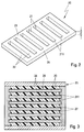
- the ladder-shaped ceramic bodies 20 thus produced are inserted into a mold 25, the individual Ceramic body 20 parallel to each other and at a distance aligned from each other.
- a cross section of a Casting mold 25 with a total of six ceramic bodies used 20 is shown in Figure 3.
- the number of ceramic bodies 20 is determined as well as the number and length of the Ceramic webs 22 in the individual ceramic bodies 20 through the intended configuration of the composite ultrasound transducer.
- the mold 25 with a Plastic material 26 poured out so that the gaps are filled in free of air pockets.
- a plastic a polymer, preferably polyurethane, is used. This plastic material 26 fills all openings 21 in the ceramic bodies 20 and all spaces 27 between the individual ceramic bodies 20.
- a polymer block 28 is formed by separating the Mold 25 is removed from the mold.
- the unmolded casting block 28 is on mutually opposite to the longitudinal direction of the Breakthroughs 21 in the individual ceramic bodies 20 themselves extending sides so far that the in the Openings 21 embedded plastic material 26 exposed on the face.
- the ceramic strips 23 and 24 on all ceramic bodies 20 and the intermediate plastic material 26 severed. There is therefore no one between the webs 22 Bridge of ceramic material more, and are in the casting block 28 now the ceramic webs forming the transducer elements 11 22 embedded in the plastic matrix 12. Since the Nominal frequency of the individual transducer elements 11 from their Depends on the length, are still the end faces of the ceramic bars 22 as far as ground until the nominal frequency is reached.
- the invention is not based on the described Embodiment limited. So the composite ultrasonic transducer not only as a surface array but also run as a linear array. In this case, only a single ceramic body 20 inserted into the mold 25 and treated in the manner described.
- the mold 25 can be made easier if on the surface of the two bridge-like ceramic strips 23,24 the ceramic body 10 spacer cams are formed, the spacer webs on the mold side make it superfluous.
- one rectangular mold 25 also a curved, in particular an annular mold can be used in which then inserted the individual ceramic bodies 10 radially become.
- acoustically decoupling Separating layers e.g. made of cork or hard foam, into which Casting mold inserted and cast with.
- the flat ones Shaped body 10 as a comb-like structure with one Comb teeth protruding comb teeth are made.
- the unmolded casting block 28 then only need the one-sided Comb back to be removed.
- the one in the plastic matrix embedded comb teeth in turn form the transducer elements 11.
- Ceramic body 10 can also be produced in a different way.
Landscapes
- Engineering & Computer Science (AREA)
- Mechanical Engineering (AREA)
- Transducers For Ultrasonic Waves (AREA)
- Piezo-Electric Transducers For Audible Bands (AREA)
Abstract
Description
- Fig.1
- ausschnittweise einen Querschnitt eines Verbund-Ultraschallwandlers,
- Fig.2
- eine perspektivische Darstellung eines Keramikkörpers zur Fertigung des Verbund-Ultraschallwandlers in Fig.1,
- Fig.3
- einen Querschnitt einer Gießform mit eingesetzten Keramikkörpern zur Fertigung des Verbund-Ultraschallwandlers in Fig.1.
Claims (10)
- Verfahren zur Herstellung eines Verbund-Ultraschallwandlers, der in Kunststoff eingelagerte, im wesentlichen in Längsrichtung abstrahlende Wandlerelemente (11) aus piezoelektrischer Keramik enthält, gekennzeichnet durch folgende Schritte:es werden flache Keramikkörper (20) erzeugt, die jeweils eine Vielzahl von voneinander beabstandeten, schlitzartigen, Durchbrüchen (21) aufweisen,mehrere Keramikkörper (20) werden mit Abstand voneinander in eine Gießform (25) eingesetzt,die Gießform (25) wird mit einem Kunstoffmaterial (26), vorzugsweise einem Polymer, ausgegossen,der nach Aushärten entstehende Gußblock (28) wird entformt undam entformten Gußblock (28) wird auf quer zur Längsrichtung der Durchbrüche (21) sich erstreckenden Seiten vorhandenes Keramikmaterial (23, 24) so weit entfernt, daß das in den Durchbrüchen (21) eingebettete Kunststoffmaterial (26) an den schmalen Seitenkanten (211) der Durchbrüche freiliegt.
- Verfahren nach Anspruch 1, dadurch gekennzeichnet, daß die flachen Keramikkörper (20) jeweils ein leiterartiges Gebilde aus zwei durch voneinander beabstandete Keramikstege (22) miteinander verbundenen Keramikstreifen (23, 24) darstellen und daß am entformten Gußblock (28) die Keramikstreifen (23, 24) entfernt werden.
- Verfahren nach Anspruch 1, dadurch gekennzeichnet, daß die flachen Keramikkörper (20) jeweils ein kammartiges Gebilde mit von einem Kammrücken zahnartig abstehenden Keramikstegen darstellen und daß am entformten Gußblock (28) die Kammrücken entfernt werden.
- Verfahren nach einem der Ansprüche 1 bis 3, dadurch gekennzeichnet, daß das Entfernen des stirnseitigen Keramikmaterials (23, 24) mittels Schneiden oder Sägen längs der schmalen Seitenkanten (211) der Durchbrüche (21) durchgeführt wird.
- Verfahren nach einem der Ansprüche 1 bis 4, dadurch gekennzeichnet, daß die zwischen den mit Kunststoffmaterial (26) gefüllten Durchbrüchen (21) verbleibenden Keramikstege (22) stirnseitig bis zum Erreichen der gewünschten Nennfrequenz des Wandlers abgeschliffen werden.
- Verfahren nach einem der Ansprüche 1 bis 5, dadurch gekennzeichnet, daß die Gießform (25) rechteckförmig ist und die Keramikkörper (20) in der Gießform (255) parallel zueinander ausgerichtet sind.
- Verfahren nach einem der Ansprüche 1 bis 5, dadurch gekennzeichnet, daß die Gießform (25) ringförmig gebogen ist und die Keramikkörper (20) radial in der Gießform (25) ausgerichtet sind.
- Verfahren nach einem der Ansprüche 1 bis 7, dadurch gekennzeichnet, daß in die Gießform (25) akustisch entkoppelnde Trennschichten eingelegt und mit vergossen werden.
- Verfahren nach einem der Ansprüch 1 bis 8, dadurch gekennzeichnet, daß die Keramikkörper (20) durch Pressen geformt und anschließend gebrannt werden.
- Verfahren nach Anspruch 9, dadurch gekennzeichnet, daß die Keramikkörper (20) mit geringer Materialstärke, vorzugsweise in Rechteckform ausgeführt werden.
Applications Claiming Priority (2)
| Application Number | Priority Date | Filing Date | Title |
|---|---|---|---|
| DE19743859A DE19743859C2 (de) | 1997-10-04 | 1997-10-04 | Verfahren zur Herstellung eines Verbund-Ultraschallwandlers |
| DE19743859 | 1997-10-04 |
Publications (2)
| Publication Number | Publication Date |
|---|---|
| EP0906791A2 true EP0906791A2 (de) | 1999-04-07 |
| EP0906791A3 EP0906791A3 (de) | 2001-07-18 |
Family
ID=7844573
Family Applications (1)
| Application Number | Title | Priority Date | Filing Date |
|---|---|---|---|
| EP98117312A Withdrawn EP0906791A3 (de) | 1997-10-04 | 1998-09-12 | Verfahren zur Herstellung eines Verbund-Ultraschallwandlers |
Country Status (5)
| Country | Link |
|---|---|
| US (1) | US6301761B1 (de) |
| EP (1) | EP0906791A3 (de) |
| DE (1) | DE19743859C2 (de) |
| NO (1) | NO320761B1 (de) |
| ZA (1) | ZA988973B (de) |
Cited By (1)
| Publication number | Priority date | Publication date | Assignee | Title |
|---|---|---|---|---|
| WO2005096400A1 (de) * | 2004-04-01 | 2005-10-13 | Smart Material Gmbh | Verfahren sowie vorrichtung zur herstellung von makrofaserkompositen |
Families Citing this family (5)
| Publication number | Priority date | Publication date | Assignee | Title |
|---|---|---|---|---|
| DE19954020C2 (de) * | 1999-11-10 | 2002-02-28 | Fraunhofer Ges Forschung | Verfahren zur Herstellung eines piezoelektrischen Wandlers |
| JP3551141B2 (ja) * | 2000-09-28 | 2004-08-04 | 松下電器産業株式会社 | 圧電体の製造方法 |
| DE10052636B4 (de) * | 2000-10-24 | 2004-07-08 | Atlas Elektronik Gmbh | Verfahren zur Herstellung eines Ultraschallwandlers |
| DE10106057C2 (de) * | 2001-02-09 | 2003-08-21 | Eads Deutschland Gmbh | Piezokeramische Platte und Verfahren zum Herstellen derselben |
| US6773197B2 (en) | 2002-10-09 | 2004-08-10 | Trw Inc. | Ball joint |
Family Cites Families (8)
| Publication number | Priority date | Publication date | Assignee | Title |
|---|---|---|---|---|
| US2752662A (en) * | 1954-12-27 | 1956-07-03 | Erie Resistor Corp | Method of making thin flat electroded ceramic elements |
| US4514247A (en) * | 1983-08-15 | 1985-04-30 | North American Philips Corporation | Method for fabricating composite transducers |
| JPH01166699A (ja) * | 1987-12-22 | 1989-06-30 | Nippon Dempa Kogyo Co Ltd | 複合圧電板の製造方法 |
| DE59008863D1 (de) * | 1990-06-21 | 1995-05-11 | Siemens Ag | Verbund-Ultraschallwandler und Verfahren zur Herstellung eines strukturierten Bauelementes aus piezoelektrischer Keramik. |
| WO1995003632A1 (en) * | 1993-07-19 | 1995-02-02 | Fiber Materials, Inc. | Method of fabricating a piezocomposite material |
| US5539965A (en) * | 1994-06-22 | 1996-07-30 | Rutgers, The University Of New Jersey | Method for making piezoelectric composites |
| US5592730A (en) * | 1994-07-29 | 1997-01-14 | Hewlett-Packard Company | Method for fabricating a Z-axis conductive backing layer for acoustic transducers using etched leadframes |
| US5691960A (en) * | 1995-08-02 | 1997-11-25 | Materials Systems, Inc. | Conformal composite acoustic transducer panel and method of fabrication thereof |
-
1997
- 1997-10-04 DE DE19743859A patent/DE19743859C2/de not_active Expired - Fee Related
-
1998
- 1998-09-12 EP EP98117312A patent/EP0906791A3/de not_active Withdrawn
- 1998-09-17 NO NO19984304A patent/NO320761B1/no unknown
- 1998-10-01 ZA ZA988973A patent/ZA988973B/xx unknown
- 1998-10-05 US US09/166,156 patent/US6301761B1/en not_active Expired - Fee Related
Cited By (1)
| Publication number | Priority date | Publication date | Assignee | Title |
|---|---|---|---|---|
| WO2005096400A1 (de) * | 2004-04-01 | 2005-10-13 | Smart Material Gmbh | Verfahren sowie vorrichtung zur herstellung von makrofaserkompositen |
Also Published As
| Publication number | Publication date |
|---|---|
| NO984304D0 (no) | 1998-09-17 |
| EP0906791A3 (de) | 2001-07-18 |
| ZA988973B (en) | 1999-04-12 |
| DE19743859A1 (de) | 1999-04-15 |
| US6301761B1 (en) | 2001-10-16 |
| NO984304L (no) | 1999-04-06 |
| NO320761B1 (no) | 2006-01-23 |
| DE19743859C2 (de) | 2000-11-16 |
Similar Documents
| Publication | Publication Date | Title |
|---|---|---|
| EP0462311B1 (de) | Verbund-Ultraschallwandler und Verfahren zur Herstellung eines strukturierten Bauelementes aus piezoelektrischer Keramik | |
| DE68920370T2 (de) | Verfahren zur Herstellung eines piezoelektrischen zusammengesetzten Wandlers. | |
| DE3214789C2 (de) | ||
| EP0412931A1 (de) | Verfahren zur Herstellung eines keramischen Schaumkörpers | |
| DE112010003083T5 (de) | Gekapseltes Keramikelement undVerfahren zum Herstellen desselben | |
| DE19743859C2 (de) | Verfahren zur Herstellung eines Verbund-Ultraschallwandlers | |
| EP1536933A2 (de) | Formeinsatz f r formmaschinen | |
| EP0189520A1 (de) | Verfahren zur Herstellung einer Array-Ultraschall-Antenne | |
| DE602004010097T2 (de) | Piezoelektrische kompositmaterialien und herstellungsverfahren dafür | |
| DE4143387C2 (de) | Verfahren zum Herstellen von Formkörpern, insbesondere von Dämmplatten | |
| EP1752593B1 (de) | Verfahren zur Herstellung von Mauersteinen sowie mit dem Verfahren hergestellter Mauerstein | |
| EP1752592B1 (de) | Verfahren zur Herstellung von Mauersteinen sowie mit dem Verfahren hergestelltes Mauersteinsystem | |
| EP1201322B1 (de) | Verfahren zur Herstellung eines Ultraschallwandlers | |
| EP2122701B1 (de) | Vielschichtbauelement sowie verfahren zur herstellung eines vielschichtbauelements | |
| DE3801603A1 (de) | Verfahren zum herstellen von aus einer natursteinschicht und einer verstaerkungsschicht bestehenden verbundkoerpern | |
| DE102018121564A1 (de) | Vorrichtung zum Herstellen von Steinformlingen für Mauerwerksteine, insbesondere Kalksandsteine, mit verstellbaren Formwänden | |
| EP1565295B1 (de) | Anordnung zur herstellung von betonformsteinen | |
| DE2316410C3 (de) | Auf Axialdruck belastbare Feder | |
| EP2146005A2 (de) | Lärmschutzelement | |
| DE1759180B2 (de) | Zwischenlage für belastete Fugen in Bauwerken | |
| DE2829569C2 (de) | Verfahren zur Herstellung von Ultraschallköpfen | |
| DE102019007023B4 (de) | Strukturbauteil und Verfahren zu dessen Herstellung | |
| EP1235284A2 (de) | Piezokeramische Platte und Verfahren zum Herstellen derselben | |
| DE2731783A1 (de) | Schallabsorber sowie verfahren zu seiner herstellung | |
| EP3272482B1 (de) | Verfahren zur herstellung von betonabstandhaltern |
Legal Events
| Date | Code | Title | Description |
|---|---|---|---|
| PUAI | Public reference made under article 153(3) epc to a published international application that has entered the european phase |
Free format text: ORIGINAL CODE: 0009012 |
|
| AK | Designated contracting states |
Kind code of ref document: A2 Designated state(s): FR GB IT |
|
| AX | Request for extension of the european patent |
Free format text: AL;LT;LV;MK;RO;SI |
|
| PUAL | Search report despatched |
Free format text: ORIGINAL CODE: 0009013 |
|
| AK | Designated contracting states |
Kind code of ref document: A3 Designated state(s): AT BE CH CY DE DK ES FI FR GB GR IE IT LI LU MC NL PT SE |
|
| AX | Request for extension of the european patent |
Free format text: AL;LT;LV;MK;RO;SI |
|
| 17P | Request for examination filed |
Effective date: 20010913 |
|
| AKX | Designation fees paid |
Free format text: FR GB IT |
|
| REG | Reference to a national code |
Ref country code: DE Ref legal event code: 8566 |
|
| RAP1 | Party data changed (applicant data changed or rights of an application transferred) |
Owner name: CERAMTEC AG INNOVATIVE CERAMIC ENGINEERING Owner name: ATLAS ELEKTRONIK GMBH |
|
| GRAP | Despatch of communication of intention to grant a patent |
Free format text: ORIGINAL CODE: EPIDOSNIGR1 |
|
| STAA | Information on the status of an ep patent application or granted ep patent |
Free format text: STATUS: THE APPLICATION IS DEEMED TO BE WITHDRAWN |
|
| 18D | Application deemed to be withdrawn |
Effective date: 20060530 |