EP0906791A2 - Method for the manufacture of a composite ultrasound transducer - Google Patents
Method for the manufacture of a composite ultrasound transducer Download PDFInfo
- Publication number
- EP0906791A2 EP0906791A2 EP98117312A EP98117312A EP0906791A2 EP 0906791 A2 EP0906791 A2 EP 0906791A2 EP 98117312 A EP98117312 A EP 98117312A EP 98117312 A EP98117312 A EP 98117312A EP 0906791 A2 EP0906791 A2 EP 0906791A2
- Authority
- EP
- European Patent Office
- Prior art keywords
- ceramic
- mold
- casting
- openings
- ceramic body
- Prior art date
- Legal status (The legal status is an assumption and is not a legal conclusion. Google has not performed a legal analysis and makes no representation as to the accuracy of the status listed.)
- Withdrawn
Links
Images

Classifications
-
- B—PERFORMING OPERATIONS; TRANSPORTING
- B06—GENERATING OR TRANSMITTING MECHANICAL VIBRATIONS IN GENERAL
- B06B—METHODS OR APPARATUS FOR GENERATING OR TRANSMITTING MECHANICAL VIBRATIONS OF INFRASONIC, SONIC, OR ULTRASONIC FREQUENCY, e.g. FOR PERFORMING MECHANICAL WORK IN GENERAL
- B06B1/00—Methods or apparatus for generating mechanical vibrations of infrasonic, sonic, or ultrasonic frequency
- B06B1/02—Methods or apparatus for generating mechanical vibrations of infrasonic, sonic, or ultrasonic frequency making use of electrical energy
- B06B1/06—Methods or apparatus for generating mechanical vibrations of infrasonic, sonic, or ultrasonic frequency making use of electrical energy operating with piezoelectric effect or with electrostriction
- B06B1/0607—Methods or apparatus for generating mechanical vibrations of infrasonic, sonic, or ultrasonic frequency making use of electrical energy operating with piezoelectric effect or with electrostriction using multiple elements
- B06B1/0622—Methods or apparatus for generating mechanical vibrations of infrasonic, sonic, or ultrasonic frequency making use of electrical energy operating with piezoelectric effect or with electrostriction using multiple elements on one surface
-
- Y—GENERAL TAGGING OF NEW TECHNOLOGICAL DEVELOPMENTS; GENERAL TAGGING OF CROSS-SECTIONAL TECHNOLOGIES SPANNING OVER SEVERAL SECTIONS OF THE IPC; TECHNICAL SUBJECTS COVERED BY FORMER USPC CROSS-REFERENCE ART COLLECTIONS [XRACs] AND DIGESTS
- Y10—TECHNICAL SUBJECTS COVERED BY FORMER USPC
- Y10T—TECHNICAL SUBJECTS COVERED BY FORMER US CLASSIFICATION
- Y10T29/00—Metal working
- Y10T29/42—Piezoelectric device making
Definitions
- the invention relates to a method for producing a Compound ultrasonic transducer, which in the preamble of Claim 1 defined genus.
- Such a composite ultrasonic transducer also composite ultrasonic transducer is made up of many small ones piezoelectrically active, individual transducer elements built up. The dimensions of the transducer elements are so designed to be essentially longitudinal radiate.
- the transducer elements of a composite ultrasonic transducer are like that in a plastic matrix stored that the longitudinal directions of the transducer elements are parallel to each other. The length of each Transducer elements determine the thickness of the composite ultrasonic transducer and thus the working frequency range.
- the invention has for its object a method for Specify manufacture of a composite ultrasound transducer, that is not subject to the aforementioned restrictions and due to short process times and extremely less Reject rate requires little cost.
- the task is in a procedure in the Oberbergiff des Claim 1 specified genus according to the invention by the Features solved in the characterizing part of claim 1.
- the process according to the invention has the advantage that it is different than not immediately in the known methods three-dimensional converter block with the multitude of through a base connected ceramic columns is produced, but first ceramic bodies as two-dimensional, ladder-like structures are created. By assembling of these two-dimensional, ladder-like structures then the three-dimensional converter block.
- the ladder-like Ceramic body itself and that in the mold Merging of the ceramic body can accordingly respective requirements for the finished converter in the Geometries of ceramics and free space can be varied.
- the ladder-like, flat ceramic bodies can be removed produce known methods, preferably Pressing methods are used, as used by the Manufacture of piezoceramic disks or cylinders are known. Are compared to the known sawing process the process times in the method according to the invention much shorter and the reject rate significantly lower.
- the method according to the invention is based on a Drawing shown embodiment of a composite ultrasonic transducer described in more detail below.
- Compound ultrasound transducers also composite ultrasound transducers called, has a variety of small, piezoelectrically active transducer elements 11 piezoelectric ceramics based on a Plastic matrix 12 made of a polymer, preferably Polyurethane, are embedded.
- the converter elements 11 have Columnar shape and are aligned so that their Longitudinal directions are parallel to each other.
- On the one Surface of the plastic matrix 12 and on one The end face of the transducer elements 11 is a continuous one Electrode 14 arranged.
- On the continuous of this Electrode 14 facing away from the surface of the plastic matrix 12 and the end face of the transducer elements 21 is one structured electrode 15 arranged.
- Electrode 15 may be structured in a ring or in a linear manner. With the structured electrode 15 are predetermined Converter elements 11 to separately controllable groups summarized. Whichever of the electrodes 14.15 in Transmission direction shows, which symbolized in Fig.1 with arrow 13 is on one electrode 14 in a known manner at least one adaptation layer 16 for adapting the acoustic impedance and on the other electrode 15 a Damping layer 17 arranged opposite to Transmitted direction 13 absorbed ultrasound.
- the composite ultrasonic transducer thus constructed is used in following process steps:
- the fat of the ceramic body 20 is relatively small and is for example less than 0.5 mm.
- the one rectangular cross-section with an optimized length Have width ratio and parallel to each other are aligned.
- the end product of the pressing process is created a ladder-like structure of one in the width of the Breakthroughs 21 corresponding distance from each other arranged ceramic webs 22 which on the long side of the plate-shaped ceramic body 20 by two bridge-like Ceramic strips 23 and 24 are interconnected.
- These ceramic webs 22 form the later converter elements 11 of the composite ultrasonic transducer in Fig.1.
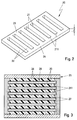
- the ladder-shaped ceramic bodies 20 thus produced are inserted into a mold 25, the individual Ceramic body 20 parallel to each other and at a distance aligned from each other.
- a cross section of a Casting mold 25 with a total of six ceramic bodies used 20 is shown in Figure 3.
- the number of ceramic bodies 20 is determined as well as the number and length of the Ceramic webs 22 in the individual ceramic bodies 20 through the intended configuration of the composite ultrasound transducer.
- the mold 25 with a Plastic material 26 poured out so that the gaps are filled in free of air pockets.
- a plastic a polymer, preferably polyurethane, is used. This plastic material 26 fills all openings 21 in the ceramic bodies 20 and all spaces 27 between the individual ceramic bodies 20.
- a polymer block 28 is formed by separating the Mold 25 is removed from the mold.
- the unmolded casting block 28 is on mutually opposite to the longitudinal direction of the Breakthroughs 21 in the individual ceramic bodies 20 themselves extending sides so far that the in the Openings 21 embedded plastic material 26 exposed on the face.
- the ceramic strips 23 and 24 on all ceramic bodies 20 and the intermediate plastic material 26 severed. There is therefore no one between the webs 22 Bridge of ceramic material more, and are in the casting block 28 now the ceramic webs forming the transducer elements 11 22 embedded in the plastic matrix 12. Since the Nominal frequency of the individual transducer elements 11 from their Depends on the length, are still the end faces of the ceramic bars 22 as far as ground until the nominal frequency is reached.
- the invention is not based on the described Embodiment limited. So the composite ultrasonic transducer not only as a surface array but also run as a linear array. In this case, only a single ceramic body 20 inserted into the mold 25 and treated in the manner described.
- the mold 25 can be made easier if on the surface of the two bridge-like ceramic strips 23,24 the ceramic body 10 spacer cams are formed, the spacer webs on the mold side make it superfluous.
- one rectangular mold 25 also a curved, in particular an annular mold can be used in which then inserted the individual ceramic bodies 10 radially become.
- acoustically decoupling Separating layers e.g. made of cork or hard foam, into which Casting mold inserted and cast with.
- the flat ones Shaped body 10 as a comb-like structure with one Comb teeth protruding comb teeth are made.
- the unmolded casting block 28 then only need the one-sided Comb back to be removed.
- the one in the plastic matrix embedded comb teeth in turn form the transducer elements 11.
- Ceramic body 10 can also be produced in a different way.
Landscapes
- Engineering & Computer Science (AREA)
- Mechanical Engineering (AREA)
- Transducers For Ultrasonic Waves (AREA)
- Piezo-Electric Transducers For Audible Bands (AREA)
Abstract
Description
Die Erfindung betrifft ein Verfahren zur Herstellung eines
Verbund-Ultraschallwandlers, der im Oberbegriff des
Anspruchs 1 definierten Gattung.The invention relates to a method for producing a
Compound ultrasonic transducer, which in the preamble of
Ein solcher Verbund-Ultraschallwandler, auch Composite-Ultraschallwandler genannt, ist aus vielen kleinen piezoelektrisch aktiven, einzelnen Wandlerelementen aufgebaut. Die Wandlerelemente sind in den Abmessungen so konzipiert, daß sie im wesentlichen in Längsrichtung abstrahlen. Die Wandlerelemente eines Verbund-Ultraschallwandlers sind in eine Kunststoffmatrix so eingelagert, daß die Längsrichtungen der Wandlerelemente zueinander parallel sind. Die Länge der einzelnen Wandlerelemente bestimmt die Dicke des VerbundUltraschallwandlers und damit den Arbeitsfrequenzbereich.Such a composite ultrasonic transducer, also composite ultrasonic transducer is made up of many small ones piezoelectrically active, individual transducer elements built up. The dimensions of the transducer elements are so designed to be essentially longitudinal radiate. The transducer elements of a composite ultrasonic transducer are like that in a plastic matrix stored that the longitudinal directions of the transducer elements are parallel to each other. The length of each Transducer elements determine the thickness of the composite ultrasonic transducer and thus the working frequency range.
Bei einem bekannten Verfahren zur Herstellung eines solchen Ultraschall-Verbundwandlers (EP 0 462 311 B1) wird zunächst eine Form aus Kunststoff so erzeugt, daß sie negative Strukturen entsprechend einer vorgegebenen Anordnung der Wandlerelemente enthält, wobei die Form die negativen Strukturen überragt. Die Form wird mit einem Keramikschlicker bis über die negativen Strukturen hinaus gefüllt und dann getrocknet und gebrannt. Beim Brennen verbrennt die Kunststofform ohne feste Rückstände, und es entsteht die nunmehr an einem Keramikboden fixierte Anordnung der Wandlerelemente. Die Hohlräume, die beim Brennen durch Ausbrennen der Kunststofform entstehen, werden mit einem Polymer vergossen, wodurch die Lage der Wandlerelemente fixiert wird und sich die mechanische Stabilität des Verbund-Ultraschallwandlers unter Erfüllung der akustischen Anforderungen ergibt. Schließlich wird der die Wandlerelemente verbindende Kreamikboden entfernt und die Stirnseiten der Wandlerelemente werden mit Elektroden belegt.In a known method for producing such Ultrasonic composite transducer (EP 0 462 311 B1) is first a mold made of plastic so that it is negative Structures according to a predetermined arrangement of the Contains transducer elements, the shape of which is negative Structures towering over. The shape comes with a Ceramic slip beyond the negative structures filled and then dried and burned. When burning burns the plastic mold without solid residue, and it arises now fixed on a ceramic floor Arrangement of the converter elements. The cavities in the Burning is caused by burning out the plastic mold, are potted with a polymer, which makes the location of the Transducer elements is fixed and the mechanical Stability of the composite ultrasonic transducer under fulfillment which results in acoustic requirements. Finally the removes the Kreamikboden connecting the transducer elements and the end faces of the transducer elements are made with electrodes busy.
Bei diesem Verfahren ist es für die saubere und verlustfreie Entformung der Kunststofform mit den Negativstrukturen der Wandleranordnung erforderlich, die Negativstrukturen, welche die Zwischenräume zwischen den einzelnen Wandlerelementen vorgeben, im Querschnitt über deren Länge zu verjüngen. Damit können nach diesem Verfahren nur Ultraschallwandler mit kegelstumpf- oder pyramidenstumpfförmig ausgebildeten Wandlerelementen erzeugt werden. Außerdem lassen sich nur begrenzte Verhältnisse zwischen Wandlerelementgeometrie und den Abständen der Wandlerelemente realisieren, wobei der Keramikanteil relativ klein ist und damit sich nur eine begrenzte akustische Leistungsfähigkeit erreichen läßt.With this procedure it is for the clean and lossless demolding of the plastic mold with the Negative structures of the transducer arrangement are required Negative structures, the spaces between the specify individual transducer elements, in cross section to taper their length. So that after this Process only ultrasonic transducers with truncated cone or truncated pyramid-shaped transducer elements be generated. In addition, only limited Relationships between transducer element geometry and Realize distances of the transducer elements, the Ceramic portion is relatively small and therefore only one can achieve limited acoustic performance.
Bei einem ebenfalls bekannten Verfahren zur Herstellung von Composite-Wandlern werden in einen mittels eines geeigneten Verfahrens hergestellten Keramikblock, einen sg. Rohling, mit einer sehr genauen arbeitenden Keramiksäge, vorzugsweise einer Inlochsäge, Schlitze in Längs- und Querrrichtung gesägt. Der Sägeschnitt erfolgt dabei nur so tief, daß noch ein durchgehender unterer Keramiksockel verbleibt. Der eingesetzte Rohling wird mit einem Polymer vorzugsweise Polyurethan, vergossen. Nach dem Verguß wird der Keramiksockel abgesägt. Die Tiefe der in den Rohling eingebrachten Sägeschnitte ist durch die gewünschte Arbeitsfrequenz (Resonanzfrequenz) des Wandlers bestimmt.In a likewise known method for producing Composite converters are made into one by means of a suitable Processed ceramic block, a so-called. Blank, with a very precise working ceramic saw, preferably an in-hole saw, slots in longitudinal and Cross cut sawn. The saw cut is only made this way deep that there is still a continuous lower ceramic base remains. The blank used is made with a polymer preferably cast in polyurethane. After the potting sawed off the ceramic base. The depth of the in the blank The saw cuts are made by the desired Working frequency (resonance frequency) of the transducer determined.
Der Nachteil dieses Verfahrens liegt in den langen Prozeßzeiten für das Sägen. Darüberhinaus ist die Ausschußrate sehr hoch, da infolge der Sprödigkeit des Xeramikmaterials sehr leicht einzelne der gesägten Säulen ausbrechen, wodurch der gesamte Rohling unbrauchbar wird.The disadvantage of this method lies in the long Process times for sawing. Furthermore, the Rejection rate very high because of the brittleness of the Xeramic material very easily single of the sawn columns break out, making the entire blank unusable.
Der Erfindung liegt die Aufgabe zugrund, ein Verfahren zur Herstellung eines Verbund-Ultraschallwandlers anzugeben, das nicht den vorgenannten Einschränkungen unterliegt und infolge kurzer Prozeßzeiten und extrem geringer Ausschußrate einen nur geringen Kosteneinsatz erfordert.The invention has for its object a method for Specify manufacture of a composite ultrasound transducer, that is not subject to the aforementioned restrictions and due to short process times and extremely less Reject rate requires little cost.
Die Aufgabe ist bei einem Verfahren der im Oberbergiff des
Anspruchs 1 angegebenen Gattung erfindungsgemäß durch die
Merkmale im Kennzeichenteil des Anspruchs 1 gelöst.The task is in a procedure in the Oberbergiff des
Das erfindungsgemäße Verfahren hat den Vorteil, daß anders als bei den bekannten Verfahren nicht sofort der dreidimensionale Wandlerblock mit der Vielzahl von durch einen Sockel verbundenen Keramiksäulen hergestellt wird, sondern zunächst Keramikkörper als zweidimensionale, leiterartige Gebilde erstellt werden. Durch Zusammenfügen dieser zweidimensionalen, leiterartigen Gebilde entsteht dann der dreidimensionale Wandlerblock. Die leiterartigen Keramikkörper selbst und die in der Gießform erfolgende Zusammenführung der Keramikkörper können entsprechend den jeweiligen Anforderungen an den fertigen Wandler in den Geometrien von Keramik und Freiraum variiert werden. Die leiterartigen, flachen Keramikkörper lassen sich nach bekannten Verfahren herstellen, wobei bevorzugt Preßverfahren angewendet werden, wie sie von der Herstellung von piezokeramischen Scheiben oder Zylindern bekannt sind. Gegenüber dem bekannten Sägeverfahren sind die Prozeßzeiten bei dem erfindungsgemäßen Verfahren wesentlich kürzer und die Ausschußquote deutlich niedriger.The process according to the invention has the advantage that it is different than not immediately in the known methods three-dimensional converter block with the multitude of through a base connected ceramic columns is produced, but first ceramic bodies as two-dimensional, ladder-like structures are created. By assembling of these two-dimensional, ladder-like structures then the three-dimensional converter block. The ladder-like Ceramic body itself and that in the mold Merging of the ceramic body can accordingly respective requirements for the finished converter in the Geometries of ceramics and free space can be varied. The ladder-like, flat ceramic bodies can be removed produce known methods, preferably Pressing methods are used, as used by the Manufacture of piezoceramic disks or cylinders are known. Are compared to the known sawing process the process times in the method according to the invention much shorter and the reject rate significantly lower.
Zweckmäßige Ausführungsformen des erfindungsgemäßen Verfahrens mit vorteilhafter Weiterbildung und Ausgestaltungen der Erfindung ergeben sich aus den weiteren Ansprüchen.Appropriate embodiments of the invention Process with advantageous training and Refinements of the invention result from the others Claims.
Das erfindungsgemäße Verfahren ist anhand eines in der Zeichnung dargestellen Ausführungsbeispiels eines Verbund-Ultraschallwandlers im folgenden näher beschrieben.The method according to the invention is based on a Drawing shown embodiment of a composite ultrasonic transducer described in more detail below.
Es zeigen, jeweils in schematischer Darstellung:
- Fig.1
- ausschnittweise einen Querschnitt eines Verbund-Ultraschallwandlers,
- Fig.2
- eine perspektivische Darstellung eines Keramikkörpers zur Fertigung des Verbund-Ultraschallwandlers in Fig.1,
- Fig.3
- einen Querschnitt einer Gießform mit eingesetzten Keramikkörpern zur Fertigung des Verbund-Ultraschallwandlers in Fig.1.
- Fig. 1
- sections of a cross section of a composite ultrasonic transducer,
- Fig. 2
- 1 shows a perspective illustration of a ceramic body for manufacturing the composite ultrasound transducer in FIG. 1,
- Fig. 3
- a cross section of a casting mold with ceramic bodies used to manufacture the composite ultrasonic transducer in Fig.1.
Der in Fig.1 ausschnittweise im Querschnitt skizzierte
Verbund-Ultraschallwandler, auch Composite-Ultraschallwandler
genannt, weist eine Vielzahl von
kleinen, piezoelektrisch aktiven Wandlerelementen 11 aus
piezoelektrischer Keramik auf, die in einer
Kunststoffmatrix 12 aus einem Polymer, vorzugsweise
Polyurethan, eingebettet sind. Die Wandlerelemente 11 haben
Säulenform und sind so ausgerichtet, daß ihre
Längsrichtungen zueinander parallel sind. Auf der einen
Oberfläche der Kunststoffmatrix 12 und auf der einen
Stirnseite der Wandlerelemente 11, ist eine durchgehende
Elektrode 14 angeordnet. Auf der von dieser durchgehenden
Elektrode 14 abgekehrten Oberfläche der Kunststoffmatrix 12
und der Stirnfläche der Wandlerelemente 21 ist eine
strukturierte Elektrode 15 angeordnet. Je nach Anwendung
des Verbund-Ultraschallwandlers, kann diese strukturierte
Elektrode 15 ringförmig oder linerar strukturiert sein. Mit
der strukturierten Elektrode 15 werden vorgegebene
Wandlerlemente 11 zu getrennt ansteuerbaren Gruppen
zusammengefaßt. Je nachdem, welche der Elektroden 14,15 in
Senderichtung zeigt, die in Fig.1 mit Pfeil 13 symbolisiert
ist, ist auf der einen Elektrode 14 in bekannter Weise
mindestens eine Anpaßschicht 16 zur Anpassung der
akustischen Impendanz und auf der anderen Elektrode 15 eine
Dämpfungschicht 17 angeordnet, die entgegen der
Senderichtung 13 abgegebenen Ultraschall absorbiert.The sketched in cross section in Fig. 1
Compound ultrasound transducers, also composite ultrasound transducers
called, has a variety of
small, piezoelectrically
Der so aufgebaute Verbund-Ultraschallwandler wird in folgenden Verfahrensschritten hergestellt:The composite ultrasonic transducer thus constructed is used in following process steps:
Zunächst werden eine Mehrzahl von plattenförmigen
Keramikkörpern 20, wie einer in Fig.2 skizziert ist, durch
Pressen und anschließendem Brennen hergestellt. Die Dicke
des Keramikkörpers 20 ist relativ gering und beträgt
beispielsweise weniger als 0,5 mm. Beim Pressen mittels
einer Preßform werden in den Keramikkörpern 20 allseits
geschlossene Durchbrüche 21 eingearbeitet, die einen
rechteckförmigen Querschnitt mit einem optimierten Längezu
Breite-Verhältnis aufweisen und parallel zueinander
ausgerichtet sind. Als Endprodukt des Preßvorgangs entsteht
ein leiterartiges Gebilde von in einem der Breite der
Durchbrüche 21 entsprechenden Abstand voneinander
angeordneten Keramikstegen 22, die auf der Längsseite des
plattenförmigen Keramikkörpers 20 durch zwei brückenartige
Keramikstreifen 23 bzw. 24 miteinander verbunden sind.
Diese Keramikstege 22 bilden die späteren Wandlerelemente
11 des Verbund-Ultraschallwandlers in Fig.1.First, a plurality of plate-shaped
Die so hergestellten, leiterförmigen Keramikkörper 20
werden in eine Gießform 25 eingesetzt, wobei die einzelnen
Keramikkörper 20 parallel zueinander und im Abstand
voneinander ausgerichtet werden. Ein Querschnitt einer
Gießform 25 mit insgesamt sechs eingesetzten Keramikkörpern
20 ist in Fig.3 dargestellt. Die Anzahl der Keramikkörper
20 bestimmt sich ebenso wie Anzahl und Länge der
Keramikstege 22 in den einzelnen Keramikkörpern 20 durch
die beabsichtigte Konfiguration des Verbund-Ultraschallwandlers.
Nunmehr wird die Gießform 25 mit einem
Kunststoffmaterial 26 so ausgegossen, daß die Zwischenräume
frei von Lufteinschlüssen ausgefüllt sind. Als Kunststoff
wird ein Polymer, vorzugsweise Polyurethan, verwendet.
Dieses Kunststoffmaterial 26 füllt alle Durchbrüche 21 in
den Keramikkörpern 20 und alle Zwischenräume 27 zwischen
den einzelnen Keramikkörpern 20 aus. Nach Aushärten des
Polymers entsteht ein Gußblock 28 der durch Abtrennen der
Gießform 25 entformt wird. Der entformte Gußblock 28 wird
auf voneinander abgekehrten quer zur Längsrichtung der
Durchbrüche 21 in den einzelnen Keramikkörpern 20 sich
erstreckenden Seiten soweit beschnitten, daß das in den
Durchbrüchen 21 eingebettete Kunststoffmaterial 26
stirnseitig freiliegt. Bezogen auf die einzelnen
Keramikkörper 20 werden also durch Entlangschneiden oder -
sägen längs der schmalen Seitenkanten 211 der Durchbrüche
21 die Keramikstreifen 23 und 24 an allen Keramikkörpern 20
sowie das dazwischenliegende Kunststoffmaterial 26
abgetrennt. Damit besteht zwischen den Stegen 22 keine
Brücke aus Keramikmaterial mehr, und im Gußblock 28 sind
nunmehr die die Wandlerelemente 11 bildenden Keramikstege
22 in der Kunststoffmatrix 12 eingebettet. Da die
Nennfrequenz der einzelnen Wandlerelemente 11 von ihrer
Länge abhängt, werden noch die Stirnseiten der Keramikstege
22 soweit abgeschliffen bis Nennfrequenz erreicht ist.The ladder-shaped
Der so hergestellte Gußblock 28 wird noch mit den
Elektroden 14 und 15 und den Schichten 16 und 17 versehen,
so daß sich nunmehr der in Fig.1 skizzierte Verbund-Ultraschallwandler
ergibt.The
Die Erfindung ist nicht auf das beschriebene
Ausführungsbeispiel beschränkt. So kann der Verbund-Ultraschallwandler
nicht nur als Flächenarray sondern auch
als Lineararray ausgeführt werden. In diesem Fall wird nur
ein einziger Keramikkörper 20 in die Gießform 25 eingesetzt
und in der beschriebenen Weise behandelt.The invention is not based on the described
Embodiment limited. So the composite ultrasonic transducer
not only as a surface array but also
run as a linear array. In this case, only
a single
Die Gießform 25 kann einfacher ausgeführt werden, wenn auf
der Oberfläche der beiden brückenartigen Keramikstreifen
23,24 der Keramikkörper 10 Abstandsnocken angeformt werden,
die die gießformseitig vorgehaltenen Abstandsstege
überflüssig werden lassen.The
Für spezielle Anwendungen kann anstelle einer
rechteckförmigen Gießform 25 auch eine gekrümmte,
insbesondere eine ringförmige Gießform verwendet werden, in
die dann die einzelnen Keramikkörper 10 radial eingesetzt
werden. Zusätzlich können noch akustisch entkoppelnde
Trennschichten, z.B. aus Kork oder Hartschaum, in die
Gießform eingelegt und mit vergossen werden.For special applications, instead of one
Anstelle von leiterartigen Gebilden können die flachen
Formkörper 10 auch als kammartige Gebilde mit von einem
Kammrücken abstehenden Kammzähnen hergestellt werden. Am
entformten Gußblock 28 brauchen dann nur noch einseitig die
Kammrücken entfernt zu werden. Die in der Kunststoffmatrix
eingebetteten Kammzähne bilden wiederum die Wandlerelemente
11.Instead of ladder-like structures, the flat ones
Shaped body 10 as a comb-like structure with one
Comb teeth protruding comb teeth are made. At the
Anstelle durch Pressen und Brennen können die flachen Keramikkörper 10 auch in anderer Weise hergestellt werden.Instead of pressing and firing, the flat ones can Ceramic body 10 can also be produced in a different way.
Claims (10)
Applications Claiming Priority (2)
| Application Number | Priority Date | Filing Date | Title |
|---|---|---|---|
| DE19743859A DE19743859C2 (en) | 1997-10-04 | 1997-10-04 | Method of manufacturing a composite ultrasonic transducer |
| DE19743859 | 1997-10-04 |
Publications (2)
| Publication Number | Publication Date |
|---|---|
| EP0906791A2 true EP0906791A2 (en) | 1999-04-07 |
| EP0906791A3 EP0906791A3 (en) | 2001-07-18 |
Family
ID=7844573
Family Applications (1)
| Application Number | Title | Priority Date | Filing Date |
|---|---|---|---|
| EP98117312A Withdrawn EP0906791A3 (en) | 1997-10-04 | 1998-09-12 | Method for the manufacture of a composite ultrasound transducer |
Country Status (5)
| Country | Link |
|---|---|
| US (1) | US6301761B1 (en) |
| EP (1) | EP0906791A3 (en) |
| DE (1) | DE19743859C2 (en) |
| NO (1) | NO320761B1 (en) |
| ZA (1) | ZA988973B (en) |
Cited By (1)
| Publication number | Priority date | Publication date | Assignee | Title |
|---|---|---|---|---|
| WO2005096400A1 (en) * | 2004-04-01 | 2005-10-13 | Smart Material Gmbh | Method and device for producing composite macrofibres |
Families Citing this family (5)
| Publication number | Priority date | Publication date | Assignee | Title |
|---|---|---|---|---|
| DE19954020C2 (en) * | 1999-11-10 | 2002-02-28 | Fraunhofer Ges Forschung | Method of manufacturing a piezoelectric transducer |
| JP3551141B2 (en) * | 2000-09-28 | 2004-08-04 | 松下電器産業株式会社 | Method of manufacturing piezoelectric body |
| DE10052636B4 (en) * | 2000-10-24 | 2004-07-08 | Atlas Elektronik Gmbh | Method of manufacturing an ultrasonic transducer |
| DE10106057C2 (en) * | 2001-02-09 | 2003-08-21 | Eads Deutschland Gmbh | Piezoceramic plate and method of making the same |
| US6773197B2 (en) | 2002-10-09 | 2004-08-10 | Trw Inc. | Ball joint |
Family Cites Families (8)
| Publication number | Priority date | Publication date | Assignee | Title |
|---|---|---|---|---|
| US2752662A (en) * | 1954-12-27 | 1956-07-03 | Erie Resistor Corp | Method of making thin flat electroded ceramic elements |
| US4514247A (en) * | 1983-08-15 | 1985-04-30 | North American Philips Corporation | Method for fabricating composite transducers |
| JPH01166699A (en) * | 1987-12-22 | 1989-06-30 | Nippon Dempa Kogyo Co Ltd | Manufacture of composite piezoelectric plate |
| EP0462311B1 (en) * | 1990-06-21 | 1995-04-05 | Siemens Aktiengesellschaft | Composite ultrasound transducer and fabrication process of a structured component from piezoelectric ceramic |
| WO1995003632A1 (en) * | 1993-07-19 | 1995-02-02 | Fiber Materials, Inc. | Method of fabricating a piezocomposite material |
| US5539965A (en) * | 1994-06-22 | 1996-07-30 | Rutgers, The University Of New Jersey | Method for making piezoelectric composites |
| US5592730A (en) * | 1994-07-29 | 1997-01-14 | Hewlett-Packard Company | Method for fabricating a Z-axis conductive backing layer for acoustic transducers using etched leadframes |
| US5691960A (en) * | 1995-08-02 | 1997-11-25 | Materials Systems, Inc. | Conformal composite acoustic transducer panel and method of fabrication thereof |
-
1997
- 1997-10-04 DE DE19743859A patent/DE19743859C2/en not_active Expired - Fee Related
-
1998
- 1998-09-12 EP EP98117312A patent/EP0906791A3/en not_active Withdrawn
- 1998-09-17 NO NO19984304A patent/NO320761B1/en unknown
- 1998-10-01 ZA ZA988973A patent/ZA988973B/en unknown
- 1998-10-05 US US09/166,156 patent/US6301761B1/en not_active Expired - Fee Related
Cited By (1)
| Publication number | Priority date | Publication date | Assignee | Title |
|---|---|---|---|---|
| WO2005096400A1 (en) * | 2004-04-01 | 2005-10-13 | Smart Material Gmbh | Method and device for producing composite macrofibres |
Also Published As
| Publication number | Publication date |
|---|---|
| US6301761B1 (en) | 2001-10-16 |
| DE19743859C2 (en) | 2000-11-16 |
| NO984304D0 (en) | 1998-09-17 |
| NO320761B1 (en) | 2006-01-23 |
| ZA988973B (en) | 1999-04-12 |
| NO984304L (en) | 1999-04-06 |
| DE19743859A1 (en) | 1999-04-15 |
| EP0906791A3 (en) | 2001-07-18 |
Similar Documents
| Publication | Publication Date | Title |
|---|---|---|
| EP0462311B1 (en) | Composite ultrasound transducer and fabrication process of a structured component from piezoelectric ceramic | |
| DE68920370T2 (en) | Method of manufacturing a piezoelectric composite transducer. | |
| DE3214789C2 (en) | ||
| DE112010003083T5 (en) | Encapsulated ceramic element and method of making the same | |
| DE19743859C2 (en) | Method of manufacturing a composite ultrasonic transducer | |
| WO2004022294A2 (en) | Moulding insert for moulding machines | |
| EP0189520A1 (en) | Method of making an ultrasonic array antenna | |
| DE4143387C2 (en) | Process for the production of moldings, in particular insulation boards | |
| EP1752593B1 (en) | Method for making building blocks and building block obtained thereby | |
| EP1752592B1 (en) | Method of making bricks and brick system made by this method | |
| EP1201322B1 (en) | Method of manufacturing an ultrasonic transducer | |
| EP3456531A1 (en) | Reinforcement structure made of flat, cellular base material and method for fabricating a three dimensional deformable, flat reinforcing structure | |
| EP2122701B1 (en) | Multi-layer component and method for producing a multi-layer component | |
| DE3801603A1 (en) | Process for producing composites comprising a layer of natural stone and a reinforcing layer | |
| DE102018121564A1 (en) | Device for producing stone moldings for masonry stones, in particular sand-lime bricks, with adjustable mold walls | |
| EP1565295B1 (en) | Arrangement for producing molded concrete bricks | |
| EP2146005A2 (en) | Noise protection element | |
| DE1759180B2 (en) | Intermediate layer for loaded joints in buildings | |
| DE2829569C2 (en) | Process for the manufacture of ultrasonic heads | |
| DE102019007023B4 (en) | Structural component and method for its manufacture | |
| EP1235284A2 (en) | Piezoceramic plate and method of manufacturing the same | |
| DE2731783A1 (en) | Sound absorber formed by pouring and fixing dense particles - comprising rubber or plastic filled with barite, metal or metal oxide powder | |
| DE2151704A1 (en) | COMPONENT MADE FROM PRESSED LIGHTWEIGHT MATERIAL | |
| EP3272482B1 (en) | Method for manufacturing concrete spacers | |
| DE1942226A1 (en) | Laminated light weight concrete panels for building - construction manufactured in a casting mould |
Legal Events
| Date | Code | Title | Description |
|---|---|---|---|
| PUAI | Public reference made under article 153(3) epc to a published international application that has entered the european phase |
Free format text: ORIGINAL CODE: 0009012 |
|
| AK | Designated contracting states |
Kind code of ref document: A2 Designated state(s): FR GB IT |
|
| AX | Request for extension of the european patent |
Free format text: AL;LT;LV;MK;RO;SI |
|
| PUAL | Search report despatched |
Free format text: ORIGINAL CODE: 0009013 |
|
| AK | Designated contracting states |
Kind code of ref document: A3 Designated state(s): AT BE CH CY DE DK ES FI FR GB GR IE IT LI LU MC NL PT SE |
|
| AX | Request for extension of the european patent |
Free format text: AL;LT;LV;MK;RO;SI |
|
| 17P | Request for examination filed |
Effective date: 20010913 |
|
| AKX | Designation fees paid |
Free format text: FR GB IT |
|
| REG | Reference to a national code |
Ref country code: DE Ref legal event code: 8566 |
|
| RAP1 | Party data changed (applicant data changed or rights of an application transferred) |
Owner name: CERAMTEC AG INNOVATIVE CERAMIC ENGINEERING Owner name: ATLAS ELEKTRONIK GMBH |
|
| GRAP | Despatch of communication of intention to grant a patent |
Free format text: ORIGINAL CODE: EPIDOSNIGR1 |
|
| STAA | Information on the status of an ep patent application or granted ep patent |
Free format text: STATUS: THE APPLICATION IS DEEMED TO BE WITHDRAWN |
|
| 18D | Application deemed to be withdrawn |
Effective date: 20060530 |