EP0906534B1 - Lösbare steckverbindung mit montageanzeige - Google Patents
Lösbare steckverbindung mit montageanzeige Download PDFInfo
- Publication number
- EP0906534B1 EP0906534B1 EP97925002A EP97925002A EP0906534B1 EP 0906534 B1 EP0906534 B1 EP 0906534B1 EP 97925002 A EP97925002 A EP 97925002A EP 97925002 A EP97925002 A EP 97925002A EP 0906534 B1 EP0906534 B1 EP 0906534B1
- Authority
- EP
- European Patent Office
- Prior art keywords
- plug
- support
- legs
- holding
- housing
- Prior art date
- Legal status (The legal status is an assumption and is not a legal conclusion. Google has not performed a legal analysis and makes no representation as to the accuracy of the status listed.)
- Expired - Lifetime
Links
Images
Classifications
-
- F—MECHANICAL ENGINEERING; LIGHTING; HEATING; WEAPONS; BLASTING
- F16—ENGINEERING ELEMENTS AND UNITS; GENERAL MEASURES FOR PRODUCING AND MAINTAINING EFFECTIVE FUNCTIONING OF MACHINES OR INSTALLATIONS; THERMAL INSULATION IN GENERAL
- F16L—PIPES; JOINTS OR FITTINGS FOR PIPES; SUPPORTS FOR PIPES, CABLES OR PROTECTIVE TUBING; MEANS FOR THERMAL INSULATION IN GENERAL
- F16L37/00—Couplings of the quick-acting type
- F16L37/08—Couplings of the quick-acting type in which the connection between abutting or axially overlapping ends is maintained by locking members
- F16L37/084—Couplings of the quick-acting type in which the connection between abutting or axially overlapping ends is maintained by locking members combined with automatic locking
- F16L37/098—Couplings of the quick-acting type in which the connection between abutting or axially overlapping ends is maintained by locking members combined with automatic locking by means of flexible hooks
- F16L37/0985—Couplings of the quick-acting type in which the connection between abutting or axially overlapping ends is maintained by locking members combined with automatic locking by means of flexible hooks the flexible hook extending radially inwardly from an outer part and engaging a bead, recess or the like on an inner part
-
- F—MECHANICAL ENGINEERING; LIGHTING; HEATING; WEAPONS; BLASTING
- F16—ENGINEERING ELEMENTS AND UNITS; GENERAL MEASURES FOR PRODUCING AND MAINTAINING EFFECTIVE FUNCTIONING OF MACHINES OR INSTALLATIONS; THERMAL INSULATION IN GENERAL
- F16L—PIPES; JOINTS OR FITTINGS FOR PIPES; SUPPORTS FOR PIPES, CABLES OR PROTECTIVE TUBING; MEANS FOR THERMAL INSULATION IN GENERAL
- F16L37/00—Couplings of the quick-acting type
- F16L37/08—Couplings of the quick-acting type in which the connection between abutting or axially overlapping ends is maintained by locking members
- F16L37/084—Couplings of the quick-acting type in which the connection between abutting or axially overlapping ends is maintained by locking members combined with automatic locking
- F16L37/0841—Couplings of the quick-acting type in which the connection between abutting or axially overlapping ends is maintained by locking members combined with automatic locking by means of a transversally slidable locking member surrounding the tube
-
- F—MECHANICAL ENGINEERING; LIGHTING; HEATING; WEAPONS; BLASTING
- F16—ENGINEERING ELEMENTS AND UNITS; GENERAL MEASURES FOR PRODUCING AND MAINTAINING EFFECTIVE FUNCTIONING OF MACHINES OR INSTALLATIONS; THERMAL INSULATION IN GENERAL
- F16L—PIPES; JOINTS OR FITTINGS FOR PIPES; SUPPORTS FOR PIPES, CABLES OR PROTECTIVE TUBING; MEANS FOR THERMAL INSULATION IN GENERAL
- F16L2201/00—Special arrangements for pipe couplings
- F16L2201/10—Indicators for correct coupling
Definitions
- the invention relates to a detachable connector with a display for connecting liquid lines according to the preamble of Claim 1.
- the retaining rib also snaps securely onto the retaining element, so that the Connection point is kept absolutely secure.
- the snap-in causes Holding rib on the spring-loaded locking edges a click sound, which the Fitter confirms the establishment of the connection, but this noise is ever after noise level in the workplace not to be made out with certainty, so that a absolute. There is no guarantee for the locking of the plug-in part.
- the Installer has the option to pull on the assembled connector to see if it stops. But there is no guarantee that the fitter will do this too Hold test, because you can not see the connector, whether this Control has already been carried out. The follow-up remains nothing else than pulling the connector again.
- the prior art according to EP 0 547 489 A1 provides a display part which can be positioned in front of the insertion opening of the housing and which consists of two support rings arranged at a distance from one another and two webs connecting the support rings to one another. While one support ring rests on the front housing wall or the front side thereof, the second support ring projects into the interior of the housing and is held by the connecting webs in a waiting position directly behind the latching edges of the holding element, and at such a distance that the holding rib of the insert part presses against the support ring shortly before it clicks into place.
- the connecting webs are in front of the housing entrance adjacent support ring, the so-called indicator section, via separable Vulnerabilities connected, which in the further penetration of the male part the interior of the housing at the latest when the locking edges snap in behind the Loosen the retaining rib.
- the release of the indicator section is intended to display a proper coupling between the male part and the connector housing serve, a tab part projecting radially from the indicator part being provided, with which the indicator part is detected and after detaching from the Connecting bars can be removed.
- the object of the invention is to design the aforementioned connector or to add that when plugging together without further manual Measures an optically clearly recognizable proof of the secure connection given is.
- the elastic spring bars offer the further advantage that not complete assembly due to the restoring forces in the webs Plug housing is pushed away from the plug-in part, so that the fitter immediately is informed and can push the connector housing firmly on again.
- the Connectable support ring housing wall two axially parallel holding webs molded, the front housing wall corresponding in the insertion area Has holding tabs into which the holding webs can be inserted and by means of radially externally projecting locking lugs can be snapped into place. That way you can Connect the display part to the plug housing at the manufacturer and the The customer can immediately bring the pre-assembled unit together with the plug-in part.
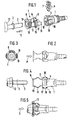
- the plug connection shown in the figures is used for the detachable connection of liquid lines, in particular fuel lines in motor vehicle construction. It generally consists of a cylindrical plug-in housing 1, a tubular plug-in part 2 with a circumferential retaining rib 3 and a display part 4 or 20 which can be connected to the plug-in housing 1 .
- the cylindrical plug-in housing 1 has in its insertion area a receiving space 5 for a separate holding element 6 , which is inserted from the outside transversely to the housing axis and is provided with radially inwardly directed locking edges 7 , which are intended to hold the retaining rib 3 after the insertion part has been pressed in 2 reach into the plug housing 1 and hold it in the closed position (cf. EP 0 605 801 B1).
- a display part 4 which can be positioned between the plug-in part 2 and plug-in housing 1 is also provided, which consists of two spaced-apart support rings 8 or 22 and 9 or 21 and two spring webs 10 which connect the support rings to one another and which on the other Opposite end faces of the support rings are formed in an elastically resilient manner and are connected to one another with outwardly arched bridge webs 11 .
- the support ring 8 shown on the right in the drawing is located in front of the opening 15 of the plug housing 1 and can be connected to the latter for the purpose of preassembly, to be described.
- the other support ring 9 is supported on the plug-in part 2 on a flange 12 behind the retaining rib 3 when the plug-in part 2 through the two ring bores 13 and 14 of the support rings 8 and 9 into the opening 15 of the plug housing 1 in the direction of the arrow " E " is pushed in. 5 , the spring bars 10 are folded together and the bridge bars 11 are curved outwards, so that these bridge bars 11 visibly protrude beyond the outer wall 16 of the plug housing 1 .
- two axially parallel holding webs 17 are formed on the outer edge of the support ring 8 , which in assembly in the direction of the arrow " M " in corresponding holding pockets 18 on the outer wall 16 of the plug-in housing 1 can be inserted and can be latched into these holding pockets 18 by means of radially outwardly projecting locking lugs 19 .
- the outwardly arched bridge webs 11 are made narrower than the spring webs 10 formed on the support rings 8 and 9 with the same material thickness .
- the display part 4 also has the further advantage that the plug-in part 2, if it is not fully inserted into the plug housing 1 and is therefore not locked behind the retaining spring 6, is clearly visible due to the restoring force of the spring bars 10 and the bridge bars 11 the plug housing 1 is pushed out. This gives the fitter a clear indication that he must push the plug-in part 2 again firmly.
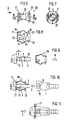
- FIGS. 6 to 8 show another embodiment of the display part, which is preassembled on the plug-in part 2 (FIG. 9) and then pressed together with it into the plug-in opening 15 .
- This display part 20 also consists of two support rings 21 and 22, which - just like the aforementioned display part 4 - are connected to one another via the same spring bars 10 and bridge bars 11 .
- the support ring 21 which is supported on the flange 12 of the insert part 2, has two support webs 23 which are resiliently formed on its inner edge and point in the direction of the other support ring 22 , which are first bent apart when the display part 20 is pressed onto the insert part 2 and after passing over the holding rib 3 again spring together and engage with the support edges 24 behind the retaining rib 3 .
- the support webs 23 have a length L which corresponds exactly to the distance a between the flange 12 and the holding rib 3 .
- the inside diameter in the area in front of the supporting edge 24 is somewhat smaller than the outside diameter R of the insert part 2.
- the outer diameter D of the supporting webs 23 in the region in front of the support edge 24 is smaller than the outer diameter H of the holding rib 3 so that for engaging behind the locking edge 7 of the support member 6 have enough behind the holding rib 3 bearing surface remains.
- the support webs 23 are designed such that they initially converge conically from the inner edge of the support ring 21 and approximately from half the length L of the support webs 23 parallel to Continue pipe jacket 25 .
- the area in front of the support edge 24 is formed so that the inner wall of the support web 23 again runs somewhat conically inwards for the optimal contact of the support webs 23 on the tubular jacket 25 .
- the support ring 22 has at its inner edge to conveniently a pointing towards the plug housing 1 centering sleeve 26 which fits accurately in the insertion opening 15 when inserting the male part 2 into the plug housing.
Landscapes
- Engineering & Computer Science (AREA)
- General Engineering & Computer Science (AREA)
- Mechanical Engineering (AREA)
- Quick-Acting Or Multi-Walled Pipe Joints (AREA)
- Connector Housings Or Holding Contact Members (AREA)
- Details Of Connecting Devices For Male And Female Coupling (AREA)
- Medical Preparation Storing Or Oral Administration Devices (AREA)
- Infusion, Injection, And Reservoir Apparatuses (AREA)
- Saccharide Compounds (AREA)
- Pens And Brushes (AREA)
- Fittings On The Vehicle Exterior For Carrying Loads, And Devices For Holding Or Mounting Articles (AREA)
- Endoscopes (AREA)
Applications Claiming Priority (3)
| Application Number | Priority Date | Filing Date | Title |
|---|---|---|---|
| DE19624524 | 1996-06-20 | ||
| DE19624524A DE19624524C2 (de) | 1996-06-20 | 1996-06-20 | Lösbare Steckverbindung mit Montageanzeige |
| PCT/EP1997/002751 WO1997048936A1 (de) | 1996-06-20 | 1997-05-28 | Lösbare steckverbindung mit montageanzeige |
Publications (2)
| Publication Number | Publication Date |
|---|---|
| EP0906534A1 EP0906534A1 (de) | 1999-04-07 |
| EP0906534B1 true EP0906534B1 (de) | 2001-05-23 |
Family
ID=7797412
Family Applications (1)
| Application Number | Title | Priority Date | Filing Date |
|---|---|---|---|
| EP97925002A Expired - Lifetime EP0906534B1 (de) | 1996-06-20 | 1997-05-28 | Lösbare steckverbindung mit montageanzeige |
Country Status (11)
| Country | Link |
|---|---|
| US (1) | US6089616A (es) |
| EP (1) | EP0906534B1 (es) |
| JP (1) | JP3190355B2 (es) |
| AT (1) | ATE201493T1 (es) |
| BR (1) | BR9709827A (es) |
| CA (1) | CA2258684A1 (es) |
| CZ (1) | CZ291893B6 (es) |
| DE (2) | DE19624524C2 (es) |
| ES (1) | ES2159136T3 (es) |
| PT (1) | PT906534E (es) |
| WO (1) | WO1997048936A1 (es) |
Families Citing this family (30)
| Publication number | Priority date | Publication date | Assignee | Title |
|---|---|---|---|---|
| DE19634521A1 (de) * | 1996-08-27 | 1998-03-05 | Opel Adam Ag | Verbindung zwischen einem ersten und einem zweiten Kupplungsstück |
| DE19822574C1 (de) * | 1998-05-20 | 1999-10-14 | Raymond A & Cie | Lösbare Schnellkupplung mit automatischer Montageanzeige |
| US6210223B1 (en) * | 1998-11-19 | 2001-04-03 | Sumitomo Wiring Systems, Ltd. | Shielded connector, a set of shielded connectors and method for connecting a shielded connector with a shielded cable |
| DE19923636A1 (de) * | 1999-05-22 | 2000-11-23 | Murrplastik Systemtechnik Gmbh | Verschraubung |
| DE10025817C2 (de) * | 2000-05-24 | 2002-06-20 | Raymond A & Cie | Lösbare Schnellkupplung mit Sicherheitsverrastung |
| FR2818731B1 (fr) * | 2000-12-22 | 2006-11-03 | Legris Sa | Coupleur rapide avec temoin de connexion |
| US6450545B1 (en) * | 2001-02-21 | 2002-09-17 | Parker Hennifin Corporation | Fluid coupling plug |
| DE10115399C1 (de) * | 2001-03-29 | 2002-06-06 | Raymond A & Cie | Lösbare Steckverbindung mit zusätzlichem Verriegelungselement |
| US20040089301A1 (en) * | 2001-10-09 | 2004-05-13 | Robert Choi | Personal hydration system with component connectivity |
| US7073688B2 (en) * | 2001-10-09 | 2006-07-11 | Camelbak Products, Llc | Personal hydration system with component connectivity |
| US20060231561A1 (en) * | 2001-10-09 | 2006-10-19 | Robert Choi | Personal hydration system with component connectivity |
| US8240719B2 (en) * | 2004-07-21 | 2012-08-14 | Parker-Hannifin Corporation | Adaptor and method for converting standard tube fitting/port to push-to-connect tube fitting/port |
| US7914050B2 (en) * | 2004-07-21 | 2011-03-29 | Parker-Hannifin Corporation | Adaptor and method for converting standard tube fitting/port to push-to-connect tube fitting/port |
| DE102004062207B3 (de) * | 2004-12-23 | 2005-10-20 | Kirchner Fraenk Rohr | Verbindungseinrichtung |
| US20060145475A1 (en) * | 2004-12-30 | 2006-07-06 | Itt Manufacturing Enterprises, Inc. | Fluid quick connector with wire retainer |
| FR2919372B1 (fr) * | 2007-07-25 | 2013-05-10 | Legris Sa | Raccord a temoin. |
| KR101138037B1 (ko) | 2010-06-29 | 2012-04-23 | 주식회사 니프코코리아 | 자동차 유체통로용 퀵 커넥터 |
| US8297659B2 (en) | 2011-02-22 | 2012-10-30 | Miniature Precision Components, Inc. | Quick connector assembly |
| CN102734583B (zh) * | 2012-07-10 | 2013-12-18 | 浙江亿日气动科技有限公司 | 快速接头 |
| FR3004780B1 (fr) * | 2013-04-17 | 2015-05-01 | Raymond A & Cie | Verrou pour raccordement tubulaire et raccord tubulaire obtenu |
| US9528644B2 (en) * | 2013-12-12 | 2016-12-27 | Zoje Kitchen & Bath Co. Ltd. | Quick connector assembly |
| JP6894815B2 (ja) * | 2017-09-22 | 2021-06-30 | 株式会社東郷製作所 | パイプ用コネクタ |
| KR102005078B1 (ko) * | 2018-01-03 | 2019-07-30 | (주)동보 | 차량의 연료 파이프용 2피스형 락킹부재 |
| US11199281B2 (en) | 2018-01-31 | 2021-12-14 | A. Raymond Et Cie. | Dual-latch quick connector |
| CN110220056B (zh) * | 2018-03-02 | 2021-04-27 | A.雷蒙德公司 | 具有双锁定机构的快速连接装置 |
| DE102018107507A1 (de) * | 2018-03-28 | 2019-10-02 | Voss Automotive Gmbh | "Anschlussvorrichtung für Medienleitungen" |
| US11898676B2 (en) | 2020-05-13 | 2024-02-13 | Mercury Plastics Llc | Quick-connect fitting |
| AT523066B1 (de) * | 2020-05-27 | 2021-05-15 | Henn Gmbh & Co Kg | Steckverbinder zum Verbinden von Leitungen für flüssige oder gasförmige Medien |
| DE102020006979B4 (de) * | 2020-11-13 | 2026-04-23 | A. Kayser Automotive Systems Gmbh | Fluidkupplung, insbesondere für Fluid führende Leitungen in Kraftfahrzeugen, Kombination aus der Fluidkupplung mit einem entsprechenden Gegenstück und Verfahren zum Herstellen einer Verbindung von zwei Fluidleitungen |
| USD995208S1 (en) | 2021-05-13 | 2023-08-15 | Hydrapak Llc | Beverage container adapter |
Family Cites Families (10)
| Publication number | Priority date | Publication date | Assignee | Title |
|---|---|---|---|---|
| JPH0538317Y2 (es) * | 1988-03-03 | 1993-09-28 | ||
| US4925217A (en) * | 1988-10-24 | 1990-05-15 | Huron Products Corporation | Quick connector with visual checking method |
| US5112085A (en) * | 1990-11-16 | 1992-05-12 | Ford Motor Company | Tube coupling with combination retainer and disassembly tool |
| DE9218634U1 (de) * | 1991-12-18 | 1994-12-01 | Itt Industries, Inc., New York, N.Y. | Haltevorrichtung für einen Kupplungsindikator |
| US5297818A (en) * | 1991-12-18 | 1994-03-29 | Itt Corporation | Retainer for pop-top indicator |
| EP0566889B1 (en) * | 1992-03-25 | 1997-07-09 | Tokai Rubber Industries, Ltd. | Quick connector |
| DE4300037C1 (de) * | 1993-01-02 | 1994-04-21 | Raymond A & Cie | Lösbare Steckverbindung |
| DE4344665A1 (de) * | 1993-12-27 | 1995-06-29 | Raymond A & Cie | Schutzkappe für eine lösbare Schnellschlußkupplung |
| US5441313A (en) * | 1994-01-18 | 1995-08-15 | Bundy Corporation | Insertion indicator for quick connector |
| US5779278A (en) * | 1995-12-27 | 1998-07-14 | Itt Automotive, Inc. | Pop off insertion indicator for metal quick connectors |
-
1996
- 1996-06-20 DE DE19624524A patent/DE19624524C2/de not_active Expired - Fee Related
-
1997
- 1997-05-28 EP EP97925002A patent/EP0906534B1/de not_active Expired - Lifetime
- 1997-05-28 JP JP50217198A patent/JP3190355B2/ja not_active Expired - Fee Related
- 1997-05-28 CA CA002258684A patent/CA2258684A1/en not_active Abandoned
- 1997-05-28 AT AT97925002T patent/ATE201493T1/de not_active IP Right Cessation
- 1997-05-28 BR BR9709827A patent/BR9709827A/pt not_active IP Right Cessation
- 1997-05-28 PT PT97925002T patent/PT906534E/pt unknown
- 1997-05-28 CZ CZ19984219A patent/CZ291893B6/cs not_active IP Right Cessation
- 1997-05-28 DE DE59703602T patent/DE59703602D1/de not_active Expired - Lifetime
- 1997-05-28 WO PCT/EP1997/002751 patent/WO1997048936A1/de not_active Ceased
- 1997-05-28 ES ES97925002T patent/ES2159136T3/es not_active Expired - Lifetime
- 1997-05-28 US US09/202,754 patent/US6089616A/en not_active Expired - Lifetime
Also Published As
| Publication number | Publication date |
|---|---|
| ES2159136T3 (es) | 2001-09-16 |
| BR9709827A (pt) | 1999-08-10 |
| CZ291893B6 (cs) | 2003-06-18 |
| ATE201493T1 (de) | 2001-06-15 |
| DE59703602D1 (de) | 2001-06-28 |
| DE19624524A1 (de) | 1998-01-02 |
| CZ421998A3 (cs) | 1999-04-14 |
| JPH11510888A (ja) | 1999-09-21 |
| DE19624524C2 (de) | 1998-07-02 |
| JP3190355B2 (ja) | 2001-07-23 |
| PT906534E (pt) | 2001-11-30 |
| EP0906534A1 (de) | 1999-04-07 |
| WO1997048936A1 (de) | 1997-12-24 |
| US6089616A (en) | 2000-07-18 |
| CA2258684A1 (en) | 1997-12-24 |
Similar Documents
| Publication | Publication Date | Title |
|---|---|---|
| EP0906534B1 (de) | Lösbare steckverbindung mit montageanzeige | |
| EP0629806B1 (de) | Kältemittelkupplung zur Verbindung von Kältemittelleitungen | |
| EP0983462B2 (de) | Lösbare schnellkupplung | |
| EP3149384B1 (de) | Steckverbinder für fluidleitungen mit innenliegender adapterhülse | |
| DE3424675C2 (de) | Schlauchkupplung | |
| EP0965014B1 (de) | Verbindungs- und anschlussstück für wellrohre | |
| DE3143015A1 (de) | Drehbare schnellkupplung | |
| DE19809313C1 (de) | Verbindungseinheit einer lösbaren Schnellkupplung für Metalleitungen | |
| EP1395771A1 (de) | Lösbare steckkupplung mit schutzhülse | |
| EP1373779A1 (de) | Lösbare steckkupplung mit zusätzlichem verriegelungselement | |
| EP1335161A1 (de) | Aufnahmeteil einer Fluid-Steckkupplung | |
| DE202008008421U1 (de) | Steckverbindung für Fluid-Leitungen | |
| EP1290370A1 (de) | Lösbare schnellkupplung mit sicherheitsklammer | |
| EP4405606A1 (de) | Steckverbinder mit vormontagesicherung | |
| EP3361135A1 (de) | Schnellverbindungsvorrichtung und schnellverbindungssystem | |
| EP0579141A1 (de) | Automatisch montierbare Steckkupplung für Leitungsschläuche in Kraftfahrzeugen | |
| WO2001065165A1 (de) | Einrichtung zum lösbaren verbinden einer druckmittelleitung mit einem druckmittelanschluss | |
| EP1838989B1 (de) | Anschlussvorrichtung f]r medienleitungen | |
| EP0579127A1 (de) | Automatisch montierbare Steckkupplung für Leitungsschläuche in Kraftfahrzeugen | |
| EP1790899B1 (de) | Steckkupplung zum Verbinden zweier Fluidleitungen | |
| EP1838987B1 (de) | Anschlussvorrichtung für medienleitungen | |
| DE102004025069B4 (de) | Vorrichtung zur Verbindung zweier Rohrabschnitte | |
| EP0949442A2 (de) | Steckverbindung zweier Fluidleitungen | |
| DE19755531A1 (de) | Lösbare Steckverbindung | |
| DE202025103960U1 (de) | Rohrsteckanordnung |
Legal Events
| Date | Code | Title | Description |
|---|---|---|---|
| PUAI | Public reference made under article 153(3) epc to a published international application that has entered the european phase |
Free format text: ORIGINAL CODE: 0009012 |
|
| 17P | Request for examination filed |
Effective date: 19980818 |
|
| AK | Designated contracting states |
Kind code of ref document: A1 Designated state(s): AT BE DE ES FR GB IT NL PT SE |
|
| GRAG | Despatch of communication of intention to grant |
Free format text: ORIGINAL CODE: EPIDOS AGRA |
|
| GRAG | Despatch of communication of intention to grant |
Free format text: ORIGINAL CODE: EPIDOS AGRA |
|
| GRAH | Despatch of communication of intention to grant a patent |
Free format text: ORIGINAL CODE: EPIDOS IGRA |
|
| 17Q | First examination report despatched |
Effective date: 20001016 |
|
| GRAH | Despatch of communication of intention to grant a patent |
Free format text: ORIGINAL CODE: EPIDOS IGRA |
|
| GRAA | (expected) grant |
Free format text: ORIGINAL CODE: 0009210 |
|
| AK | Designated contracting states |
Kind code of ref document: B1 Designated state(s): AT BE DE ES FR GB IT NL PT SE |
|
| REF | Corresponds to: |
Ref document number: 201493 Country of ref document: AT Date of ref document: 20010615 Kind code of ref document: T |
|
| REF | Corresponds to: |
Ref document number: 59703602 Country of ref document: DE Date of ref document: 20010628 |
|
| ET | Fr: translation filed | ||
| ITF | It: translation for a ep patent filed | ||
| GBT | Gb: translation of ep patent filed (gb section 77(6)(a)/1977) |
Effective date: 20010807 |
|
| REG | Reference to a national code |
Ref country code: ES Ref legal event code: FG2A Ref document number: 2159136 Country of ref document: ES Kind code of ref document: T3 |
|
| REG | Reference to a national code |
Ref country code: PT Ref legal event code: SC4A Free format text: AVAILABILITY OF NATIONAL TRANSLATION Effective date: 20010822 |
|
| REG | Reference to a national code |
Ref country code: GB Ref legal event code: IF02 |
|
| PLBE | No opposition filed within time limit |
Free format text: ORIGINAL CODE: 0009261 |
|
| STAA | Information on the status of an ep patent application or granted ep patent |
Free format text: STATUS: NO OPPOSITION FILED WITHIN TIME LIMIT |
|
| 26N | No opposition filed | ||
| PGFP | Annual fee paid to national office [announced via postgrant information from national office to epo] |
Ref country code: ES Payment date: 20030514 Year of fee payment: 7 |
|
| PGFP | Annual fee paid to national office [announced via postgrant information from national office to epo] |
Ref country code: GB Payment date: 20030520 Year of fee payment: 7 Ref country code: PT Payment date: 20030520 Year of fee payment: 7 |
|
| PG25 | Lapsed in a contracting state [announced via postgrant information from national office to epo] |
Ref country code: GB Free format text: LAPSE BECAUSE OF NON-PAYMENT OF DUE FEES Effective date: 20040528 |
|
| PG25 | Lapsed in a contracting state [announced via postgrant information from national office to epo] |
Ref country code: ES Free format text: LAPSE BECAUSE OF NON-PAYMENT OF DUE FEES Effective date: 20040529 |
|
| PG25 | Lapsed in a contracting state [announced via postgrant information from national office to epo] |
Ref country code: PT Free format text: LAPSE BECAUSE OF NON-PAYMENT OF DUE FEES Effective date: 20041129 |
|
| GBPC | Gb: european patent ceased through non-payment of renewal fee | ||
| REG | Reference to a national code |
Ref country code: PT Ref legal event code: MM4A Free format text: LAPSE DUE TO NON-PAYMENT OF FEES Effective date: 20041129 |
|
| PGFP | Annual fee paid to national office [announced via postgrant information from national office to epo] |
Ref country code: AT Payment date: 20050523 Year of fee payment: 9 |
|
| PG25 | Lapsed in a contracting state [announced via postgrant information from national office to epo] |
Ref country code: IT Free format text: LAPSE BECAUSE OF NON-PAYMENT OF DUE FEES Effective date: 20050528 |
|
| REG | Reference to a national code |
Ref country code: ES Ref legal event code: FD2A Effective date: 20040529 |
|
| PG25 | Lapsed in a contracting state [announced via postgrant information from national office to epo] |
Ref country code: AT Free format text: LAPSE BECAUSE OF NON-PAYMENT OF DUE FEES Effective date: 20060528 |
|
| PGFP | Annual fee paid to national office [announced via postgrant information from national office to epo] |
Ref country code: BE Payment date: 20080526 Year of fee payment: 12 |
|
| PGFP | Annual fee paid to national office [announced via postgrant information from national office to epo] |
Ref country code: SE Payment date: 20080519 Year of fee payment: 12 Ref country code: NL Payment date: 20080516 Year of fee payment: 12 |
|
| PGFP | Annual fee paid to national office [announced via postgrant information from national office to epo] |
Ref country code: FR Payment date: 20090518 Year of fee payment: 13 |
|
| BERE | Be: lapsed |
Owner name: A. *RAYMOND & CIE Effective date: 20090531 |
|
| NLV4 | Nl: lapsed or anulled due to non-payment of the annual fee |
Effective date: 20091201 |
|
| PG25 | Lapsed in a contracting state [announced via postgrant information from national office to epo] |
Ref country code: NL Free format text: LAPSE BECAUSE OF NON-PAYMENT OF DUE FEES Effective date: 20091201 |
|
| PG25 | Lapsed in a contracting state [announced via postgrant information from national office to epo] |
Ref country code: BE Free format text: LAPSE BECAUSE OF NON-PAYMENT OF DUE FEES Effective date: 20090531 |
|
| REG | Reference to a national code |
Ref country code: FR Ref legal event code: ST Effective date: 20110131 |
|
| PG25 | Lapsed in a contracting state [announced via postgrant information from national office to epo] |
Ref country code: FR Free format text: LAPSE BECAUSE OF NON-PAYMENT OF DUE FEES Effective date: 20100531 Ref country code: SE Free format text: LAPSE BECAUSE OF NON-PAYMENT OF DUE FEES Effective date: 20090529 |
|
| REG | Reference to a national code |
Ref country code: DE Ref legal event code: R082 Ref document number: 59703602 Country of ref document: DE |
|
| PGFP | Annual fee paid to national office [announced via postgrant information from national office to epo] |
Ref country code: DE Payment date: 20160520 Year of fee payment: 20 |
|
| REG | Reference to a national code |
Ref country code: DE Ref legal event code: R071 Ref document number: 59703602 Country of ref document: DE |