EP0906534B1 - Releasable plug connector with fitting indicator - Google Patents
Releasable plug connector with fitting indicator Download PDFInfo
- Publication number
- EP0906534B1 EP0906534B1 EP97925002A EP97925002A EP0906534B1 EP 0906534 B1 EP0906534 B1 EP 0906534B1 EP 97925002 A EP97925002 A EP 97925002A EP 97925002 A EP97925002 A EP 97925002A EP 0906534 B1 EP0906534 B1 EP 0906534B1
- Authority
- EP
- European Patent Office
- Prior art keywords
- plug
- support
- legs
- holding
- housing
- Prior art date
- Legal status (The legal status is an assumption and is not a legal conclusion. Google has not performed a legal analysis and makes no representation as to the accuracy of the status listed.)
- Expired - Lifetime
Links
Images
Classifications
-
- F—MECHANICAL ENGINEERING; LIGHTING; HEATING; WEAPONS; BLASTING
- F16—ENGINEERING ELEMENTS AND UNITS; GENERAL MEASURES FOR PRODUCING AND MAINTAINING EFFECTIVE FUNCTIONING OF MACHINES OR INSTALLATIONS; THERMAL INSULATION IN GENERAL
- F16L—PIPES; JOINTS OR FITTINGS FOR PIPES; SUPPORTS FOR PIPES, CABLES OR PROTECTIVE TUBING; MEANS FOR THERMAL INSULATION IN GENERAL
- F16L37/00—Couplings of the quick-acting type
- F16L37/08—Couplings of the quick-acting type in which the connection between abutting or axially overlapping ends is maintained by locking members
- F16L37/084—Couplings of the quick-acting type in which the connection between abutting or axially overlapping ends is maintained by locking members combined with automatic locking
- F16L37/098—Couplings of the quick-acting type in which the connection between abutting or axially overlapping ends is maintained by locking members combined with automatic locking by means of flexible hooks
- F16L37/0985—Couplings of the quick-acting type in which the connection between abutting or axially overlapping ends is maintained by locking members combined with automatic locking by means of flexible hooks the flexible hook extending radially inwardly from an outer part and engaging a bead, recess or the like on an inner part
-
- F—MECHANICAL ENGINEERING; LIGHTING; HEATING; WEAPONS; BLASTING
- F16—ENGINEERING ELEMENTS AND UNITS; GENERAL MEASURES FOR PRODUCING AND MAINTAINING EFFECTIVE FUNCTIONING OF MACHINES OR INSTALLATIONS; THERMAL INSULATION IN GENERAL
- F16L—PIPES; JOINTS OR FITTINGS FOR PIPES; SUPPORTS FOR PIPES, CABLES OR PROTECTIVE TUBING; MEANS FOR THERMAL INSULATION IN GENERAL
- F16L37/00—Couplings of the quick-acting type
- F16L37/08—Couplings of the quick-acting type in which the connection between abutting or axially overlapping ends is maintained by locking members
- F16L37/084—Couplings of the quick-acting type in which the connection between abutting or axially overlapping ends is maintained by locking members combined with automatic locking
- F16L37/0841—Couplings of the quick-acting type in which the connection between abutting or axially overlapping ends is maintained by locking members combined with automatic locking by means of a transversally slidable locking member surrounding the tube
-
- F—MECHANICAL ENGINEERING; LIGHTING; HEATING; WEAPONS; BLASTING
- F16—ENGINEERING ELEMENTS AND UNITS; GENERAL MEASURES FOR PRODUCING AND MAINTAINING EFFECTIVE FUNCTIONING OF MACHINES OR INSTALLATIONS; THERMAL INSULATION IN GENERAL
- F16L—PIPES; JOINTS OR FITTINGS FOR PIPES; SUPPORTS FOR PIPES, CABLES OR PROTECTIVE TUBING; MEANS FOR THERMAL INSULATION IN GENERAL
- F16L2201/00—Special arrangements for pipe couplings
- F16L2201/10—Indicators for correct coupling
Definitions
- the invention relates to a detachable connector with a display for connecting liquid lines according to the preamble of Claim 1.
- the retaining rib also snaps securely onto the retaining element, so that the Connection point is kept absolutely secure.
- the snap-in causes Holding rib on the spring-loaded locking edges a click sound, which the Fitter confirms the establishment of the connection, but this noise is ever after noise level in the workplace not to be made out with certainty, so that a absolute. There is no guarantee for the locking of the plug-in part.
- the Installer has the option to pull on the assembled connector to see if it stops. But there is no guarantee that the fitter will do this too Hold test, because you can not see the connector, whether this Control has already been carried out. The follow-up remains nothing else than pulling the connector again.
- the prior art according to EP 0 547 489 A1 provides a display part which can be positioned in front of the insertion opening of the housing and which consists of two support rings arranged at a distance from one another and two webs connecting the support rings to one another. While one support ring rests on the front housing wall or the front side thereof, the second support ring projects into the interior of the housing and is held by the connecting webs in a waiting position directly behind the latching edges of the holding element, and at such a distance that the holding rib of the insert part presses against the support ring shortly before it clicks into place.
- the connecting webs are in front of the housing entrance adjacent support ring, the so-called indicator section, via separable Vulnerabilities connected, which in the further penetration of the male part the interior of the housing at the latest when the locking edges snap in behind the Loosen the retaining rib.
- the release of the indicator section is intended to display a proper coupling between the male part and the connector housing serve, a tab part projecting radially from the indicator part being provided, with which the indicator part is detected and after detaching from the Connecting bars can be removed.
- the object of the invention is to design the aforementioned connector or to add that when plugging together without further manual Measures an optically clearly recognizable proof of the secure connection given is.
- the elastic spring bars offer the further advantage that not complete assembly due to the restoring forces in the webs Plug housing is pushed away from the plug-in part, so that the fitter immediately is informed and can push the connector housing firmly on again.
- the Connectable support ring housing wall two axially parallel holding webs molded, the front housing wall corresponding in the insertion area Has holding tabs into which the holding webs can be inserted and by means of radially externally projecting locking lugs can be snapped into place. That way you can Connect the display part to the plug housing at the manufacturer and the The customer can immediately bring the pre-assembled unit together with the plug-in part.
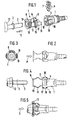
- the plug connection shown in the figures is used for the detachable connection of liquid lines, in particular fuel lines in motor vehicle construction. It generally consists of a cylindrical plug-in housing 1, a tubular plug-in part 2 with a circumferential retaining rib 3 and a display part 4 or 20 which can be connected to the plug-in housing 1 .
- the cylindrical plug-in housing 1 has in its insertion area a receiving space 5 for a separate holding element 6 , which is inserted from the outside transversely to the housing axis and is provided with radially inwardly directed locking edges 7 , which are intended to hold the retaining rib 3 after the insertion part has been pressed in 2 reach into the plug housing 1 and hold it in the closed position (cf. EP 0 605 801 B1).
- a display part 4 which can be positioned between the plug-in part 2 and plug-in housing 1 is also provided, which consists of two spaced-apart support rings 8 or 22 and 9 or 21 and two spring webs 10 which connect the support rings to one another and which on the other Opposite end faces of the support rings are formed in an elastically resilient manner and are connected to one another with outwardly arched bridge webs 11 .
- the support ring 8 shown on the right in the drawing is located in front of the opening 15 of the plug housing 1 and can be connected to the latter for the purpose of preassembly, to be described.
- the other support ring 9 is supported on the plug-in part 2 on a flange 12 behind the retaining rib 3 when the plug-in part 2 through the two ring bores 13 and 14 of the support rings 8 and 9 into the opening 15 of the plug housing 1 in the direction of the arrow " E " is pushed in. 5 , the spring bars 10 are folded together and the bridge bars 11 are curved outwards, so that these bridge bars 11 visibly protrude beyond the outer wall 16 of the plug housing 1 .
- two axially parallel holding webs 17 are formed on the outer edge of the support ring 8 , which in assembly in the direction of the arrow " M " in corresponding holding pockets 18 on the outer wall 16 of the plug-in housing 1 can be inserted and can be latched into these holding pockets 18 by means of radially outwardly projecting locking lugs 19 .
- the outwardly arched bridge webs 11 are made narrower than the spring webs 10 formed on the support rings 8 and 9 with the same material thickness .
- the display part 4 also has the further advantage that the plug-in part 2, if it is not fully inserted into the plug housing 1 and is therefore not locked behind the retaining spring 6, is clearly visible due to the restoring force of the spring bars 10 and the bridge bars 11 the plug housing 1 is pushed out. This gives the fitter a clear indication that he must push the plug-in part 2 again firmly.
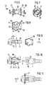
- FIGS. 6 to 8 show another embodiment of the display part, which is preassembled on the plug-in part 2 (FIG. 9) and then pressed together with it into the plug-in opening 15 .
- This display part 20 also consists of two support rings 21 and 22, which - just like the aforementioned display part 4 - are connected to one another via the same spring bars 10 and bridge bars 11 .
- the support ring 21 which is supported on the flange 12 of the insert part 2, has two support webs 23 which are resiliently formed on its inner edge and point in the direction of the other support ring 22 , which are first bent apart when the display part 20 is pressed onto the insert part 2 and after passing over the holding rib 3 again spring together and engage with the support edges 24 behind the retaining rib 3 .
- the support webs 23 have a length L which corresponds exactly to the distance a between the flange 12 and the holding rib 3 .
- the inside diameter in the area in front of the supporting edge 24 is somewhat smaller than the outside diameter R of the insert part 2.
- the outer diameter D of the supporting webs 23 in the region in front of the support edge 24 is smaller than the outer diameter H of the holding rib 3 so that for engaging behind the locking edge 7 of the support member 6 have enough behind the holding rib 3 bearing surface remains.
- the support webs 23 are designed such that they initially converge conically from the inner edge of the support ring 21 and approximately from half the length L of the support webs 23 parallel to Continue pipe jacket 25 .
- the area in front of the support edge 24 is formed so that the inner wall of the support web 23 again runs somewhat conically inwards for the optimal contact of the support webs 23 on the tubular jacket 25 .
- the support ring 22 has at its inner edge to conveniently a pointing towards the plug housing 1 centering sleeve 26 which fits accurately in the insertion opening 15 when inserting the male part 2 into the plug housing.
Landscapes
- Engineering & Computer Science (AREA)
- General Engineering & Computer Science (AREA)
- Mechanical Engineering (AREA)
- Quick-Acting Or Multi-Walled Pipe Joints (AREA)
- Connector Housings Or Holding Contact Members (AREA)
- Details Of Connecting Devices For Male And Female Coupling (AREA)
- Medical Preparation Storing Or Oral Administration Devices (AREA)
- Infusion, Injection, And Reservoir Apparatuses (AREA)
- Fittings On The Vehicle Exterior For Carrying Loads, And Devices For Holding Or Mounting Articles (AREA)
- Saccharide Compounds (AREA)
- Endoscopes (AREA)
- Pens And Brushes (AREA)
Abstract
Description
Die Erfindung bezieht sich auf eine lösbare Steckverbindung mit Montageanzeige
zum Verbinden von Flüssigkeitsleitungen entsprechend dem Oberbegriff des
Anspruchs 1 .The invention relates to a detachable connector with a display
for connecting liquid lines according to the preamble of
Beim Zusammenbringen von Einsteckteil und Steckgehäuse kommt es besonders darauf an, daß die Halterippe auch sicher am Halteelement einrastet, so daß die Verbindungsstelle absolut sicher gehalten wird. Zwar verursacht das Einrasten der Halterippe an den auffederbaren Rastkanten ein Klick-Geräusch, welches dem Monteur die Herstellung der Verbindung bestätigt, doch ist dieses Geräusch je nach Lärmpegel am Arbeitsplatz nicht mit Sicherheit auszumachen, so daß eine absolute. Gewähr für die Verrastung des Einsteckteils nicht gegeben ist.When the plug-in part and plug-in housing are brought together, it is particularly important to the fact that the retaining rib also snaps securely onto the retaining element, so that the Connection point is kept absolutely secure. The snap-in causes Holding rib on the spring-loaded locking edges a click sound, which the Fitter confirms the establishment of the connection, but this noise is ever after noise level in the workplace not to be made out with certainty, so that a absolute. There is no guarantee for the locking of the plug-in part.
Um sich bei der Montage vom Einrasten der Halterippe zu vergewissern, hat der Monteur zwar die Möglichkeit, an der montierten Steckverbindung zu ziehen, um zu sehen, ob sie hält. Doch gibt es keine Gewähr, daß der Monteur auch diese Halteprobe durchgeführt hat, da man der Steckverbindung nicht ansieht, ob diese Kontrolle auch schon durchgeführt worden ist. Der Nachkontrolle bleibt somit nichts anderes übrig, als nochmals an der Steckverbindung zu ziehen.To ensure that the retaining rib snaps into place during assembly, the Installer has the option to pull on the assembled connector to see if it stops. But there is no guarantee that the fitter will do this too Hold test, because you can not see the connector, whether this Control has already been carried out. The follow-up remains nothing else than pulling the connector again.
Um diese Kontrolle zu verbessern, ist beim Stand der Technik nach EP 0 547 489 A1 ein vor der Einstecköffnung des Gehäuses positionierbares Anzeigeteil vorgesehen, welches aus zwei im Abstand voneinander angeordneten Stützringen und zwei die Stützringe miteinander verbindenden Stegen besteht. Während der eine Stützring an der vorderen Gehäusewand bzw. deren Stirnseite anliegt, ragt der zweite Stützring in den Gehäuseinnenraum hinein und wird durch die Verbindungsstege in einer Warteposition direkt hinter den Rastkanten des Halteelements gehalten, und zwar in einem solchen Abstand, daß die Halterippe des Einsteckteils kurz vor dem Einrasten an den Rastkanten gegen den Stützring drückt.In order to improve this control, the prior art according to EP 0 547 489 A1 provides a display part which can be positioned in front of the insertion opening of the housing and which consists of two support rings arranged at a distance from one another and two webs connecting the support rings to one another. While one support ring rests on the front housing wall or the front side thereof, the second support ring projects into the interior of the housing and is held by the connecting webs in a waiting position directly behind the latching edges of the holding element, and at such a distance that the holding rib of the insert part presses against the support ring shortly before it clicks into place.
Die Verbindungsstege sind hierbei mit dem vor dem Gehäuseeingang anliegenden Stützring, dem sogenannten indikatorabschnitt, über trennbare Schwachstellen verbunden, welche beim weiteren Eindringen des Einsteckteils in den Gehäuseinnenraum spätestens beim Einrasten der Rastkanten hinter der Halterippe sich lösen. Das Lösen des Indikatorabschnitts soll zur Anzeige einer ordnungsgemäßen Kopplung zwischen den Einsteckteil und dem Steckergehäuse dienen, wobei ein vom Indikatorteil radial abstehendes Laschenteil vorgesehen ist, mit welchem das Indikatorteil erfaßt und nach dem Lösen von den Verbindungsstegen entfernt werden kann.The connecting webs are in front of the housing entrance adjacent support ring, the so-called indicator section, via separable Vulnerabilities connected, which in the further penetration of the male part the interior of the housing at the latest when the locking edges snap in behind the Loosen the retaining rib. The release of the indicator section is intended to display a proper coupling between the male part and the connector housing serve, a tab part projecting radially from the indicator part being provided, with which the indicator part is detected and after detaching from the Connecting bars can be removed.
Das Fehlen der Lasche mit dem zugehörigen Indikatorteil ist somit ein sicherer Beweis, daß die Steckverbindung geschlossen ist; andernfalls hätte der Monteur die Lasche nicht entfernen können. Doch erfordert auch diese Art der Kontrolle einen zusätzlichen Arbeitsaufwand, so daß mit dem kostspieligen Anzeigeteil gegenüber dem Ziehen an dem montierten Einsteckteil im Grunde nichts an Arbeitszeit eingespart worden ist.The absence of the tab with the associated indicator part is therefore a safer one Proof that the connector is closed; otherwise the fitter would have cannot remove the tab. However, this type of control also requires an additional amount of work, so that with the expensive display part compared to pulling on the assembled plug-in part, basically nothing Working time has been saved.
Aufgabe der Erfindung ist es, die vorgenannte Steckverbindung so zu gestalten bzw. zu ergänzen, daß beim Zusammenstecken ohne weitere manuellen Maßnahmen ein optisch gut erkennbarer Beweis für die sichere Verbindung gegeben ist.The object of the invention is to design the aforementioned connector or to add that when plugging together without further manual Measures an optically clearly recognizable proof of the secure connection given is.
Diese Aufgabe wird nach den kennzeichnenden Merkmalen des Anspruchs 1
dadurch gelöst, daß der andere, von der Gehäusewand abgekehrte Stützring am
Einsteckteil an einem Flansch hinter der Halterippe abstützbar ist und die Stege
an beiden Stützringen elastisch auffederbar angeformt und untereinander mit
nach außen gewölbten Brückenstegen verbunden sind, welche beim Eindrücken
des Einsteckteils nach außen zusammenklappen und dabei die Gehäusewand
sichtbar überragen.This object is achieved according to the characterizing features of
Die elastischen Federstege bieten hierbei noch den weiteren Vorteil, daß bei nicht vollständiger Montage aufgrund der Rückstellkräfte in den Stegen das Steckgehäuse vom Einsteckteil weggedrückt wird, so daß der Monteur sofort informiert ist und das Steckgehäuse nochmals fest aufdrücken kann.The elastic spring bars offer the further advantage that not complete assembly due to the restoring forces in the webs Plug housing is pushed away from the plug-in part, so that the fitter immediately is informed and can push the connector housing firmly on again.
Um das Positionieren des Anzeigeteils zwischen dem Einsteckteil und dem Steckgehäuse zu erleichtern, sind zwei Möglichkeiten der Vormontage vorgesehen.To position the display part between the male part and the To facilitate plug-in housings are two options for pre-assembly intended.
Bei der Ausführungsform nach Anspruch 2 sind am Außenrand des mit der
Gehäusewand verbindbaren Stützringes zwei achsparallel verlaufende Haltestege
angeformt, wobei die vordere Gehäusewand im Einführbereich entsprechende
Haltelaschen aufweist, in welche die Haltestege einführbar und mittels radial nach
außen abstehender Rastnasen einrastbar sind. Auf diese Weise läßt sich das
Anzeigeteil mit dem Steckgehäuse problemlos beim Hersteller verbinden und der
Kunde kann die vormontierte Einheit sofort mit dem Einsteckteil zusammenführen.In the embodiment according to
Bei der anderen Ausführungsform nach Anspruch 3 besitzt der sich am Flansch
des Einsteckteils abstützende Stützring mindestens zwei an dessen Innenrand
auffederbar angeformte, in Richtung auf den anderen Stützring weisende
Stützstege, deren Länge dem Abstand zwischen dem Flansch und der Halterippe
entspricht und deren Innendurchmesser im Bereich vor der Stützkante etwas
kleiner ist als der Rohrdurchmesser des Einsteckteils. Dadurch läßt sich das
Anzeigeteil bequem auf dem Einsteckteil vormontieren und dann beim Kunden mit
dem Steckgehäuse zusammenführen. Ein weiterer Vorteil dieser Ausführungsform
besteht darin, daß die Baulänge des Einsteckteils nicht verändert wird, weil das
Anzeigeteil kürzer ist als die Gesamtlänge des rohrförmigen Teils.In the other embodiment according to
Die in den Ansprüchen 4 bis 6 angeführten Merkmale beziehen sich auf eine
zweckmäßige Ausformung und Dimensionierung der im Anspruch 3 erwähnten
Stützstege, damit diese nach dem Aufstecken des Anzeigeteils auf das
Einsteckteil vor der Halterippe eng am Rohrstück anliegen ( Ansprüche 4 und 6 )
und das Halteelement des Steckgehäuses genügend Platz hat, um die Halterippe
zu hintergreifen ( Anspruch 5 ). Schließlich ist nach Anspruch 7 noch vorgesehen,
daß die nach außen gewölbten Brückenstege schmaler und damit flexibler sind
als die an den Stützringen angeformten Federstege. Dadurch wird erreicht, daß
beim Zusammenklappen der Federstege die gewölbten Brückenstege sich ohne
großen Kraftaufwand zu einem Kreis zusammen schließen.The features listed in
In der Zeichnung sind zwei Ausführungsbeispiele der Erfindung dargestellt und sollen nachfolgend näher beschrieben werden. Es zeigt
- Fig. 1
- die Hauptelemente der Steckverbindung mit einem am Steckgehäuse vormontierbaren Anzeigeteil vor dem Zusammenbau,
- Fig. 2
- das Steckgehäuse mit montiertem Anzeigeteil in Seitenansicht,
- Fig. 3
- das Steckgehäuse mit Anzeigeteil in Draufsicht von rechts,
- Fig. 4
- das Steckgehäuse mit montiertem Anzeigeteil in einer um 90° gedrehten Seitenansicht mit zugehörigem Einsteckteil vor dem Eindrücken,
- Fig. 5
- das gleiche Steckgehäuse mit eingedrückten Einsteckteil und zusammengeklapptem Anzeigeteil,
- Fig. 6
- eine andere am Einsteckteil vormontierbare Ausführungsform des Anzeigeteils in Seitenansicht,
- Fig. 7
- das gleiche Anzeigeteil in einer Draufsicht in Richtung des Pfeiles A,
- Fig.8
- einen Längsschnitt durch das Anzeigeteil gemäß Linie VIII-VIII
in
Figur 6, - Fig. 9
- das Einsteckteil mit Anzeigeteil vor dem Aufdrücken,
- Fig. 10
- das Einsteckteil mit vormontiertem Anzeigeteil vor dem Eindrücken in das Steckaehäuse und
- Fig. 11
- das gleiche Montagebild mit eingedrücktem Einsteckteil und zusammengeklapptem Anzeigeteil.
- Fig. 1
- the main elements of the plug connection with a display part which can be pre-assembled on the plug housing before assembly,
- Fig. 2
- the plug housing with mounted display part in side view,
- Fig. 3
- the plug housing with display part in a top view from the right,
- Fig. 4
- the plug housing with the mounted display part in a side view rotated by 90 ° with the associated plug-in part before being pushed in,
- Fig. 5
- the same plug-in housing with the push-in part pushed in and the display part folded,
- Fig. 6
- another embodiment of the display part which can be preassembled on the plug-in part, in side view,
- Fig. 7
- the same display part in a plan view in the direction of arrow A,
- Fig. 8
- 6 shows a longitudinal section through the display part according to line VIII-VIII in FIG. 6,
- Fig. 9
- the insert part with display part before pressing on,
- Fig. 10
- the plug-in part with the pre-assembled display part before being pushed into the plug housing and
- Fig. 11
- the same assembly picture with the inserted part and the folded display part.
Die in den Figuren dargestellte Steckverbindung dient zur lösbaren Verbindung
von Flüssigkeitsleitungen, insbesondere von Kraftstoffleitungen im Kraftfahrzeugbau.
Sie besteht generell aus einem zylindrischen Steckgehäuse 1, einem
rohrförmigen Einsteckteil 2 mit einer umlaufenden Halterippe 3 sowie einem mit
dem Steckgehäuse 1 verbindbaren Anzeigeteil 4 bzw. 20. The plug connection shown in the figures is used for the detachable connection of liquid lines, in particular fuel lines in motor vehicle construction. It generally consists of a cylindrical plug-in
Das zylindrische Steckgehäuse 1 weist in seinem Einsteckbereich einen
Aufnahmeraum 5 für ein separates Halteelement 6 auf, welches von außen quer
zur Gehäuseachse eingeführt wird und mit radial nach innen gerichteten
Rastkanten 7 versehen ist, welche dazu bestimmt sind, die Halterippe 3 nach dem
Eindrücken des Einsteckteils 2 in das Steckgehäuse 1 zu hintergreifen und in
Schließposition zu halten (vgl. EP 0 605 801 B1).The cylindrical plug-in
Zum Beweis der korrekten Montage ist ferner ein zwischen Einsteckteil 2 und
Steckgehäuse 1 positionierbares Anzeigeteil 4 vorgesehen, welches aus zwei im
Abstand voneinander angeordneten Stützringen 8 bzw. 22 und 9 bzw. 21 und
zwei die Stützringe miteinander verbindenden Federstegen 10 besteht, die an den
einander gegenüberliegenden Stirnflächen der Stützringe elastisch auffederbar
angeformt und untereinander mit nach außen gewölbten Brückenstegen 11
verbunden sind.To prove the correct assembly, a
Beim Ausführungsbeispiel nach Figur 1 bis 5 befindet sich der in der Zeichnung
rechts dargestellte Stützring 8 vor der Öffnung 15 des Steckgehäuses 1 und kann
zwecks Vormontage in noch zu beschreibender Weise mit letzterem verbunden
werden. Der andere Stützring 9 stützt sich am Einsteckteil 2 an einem Flansch 12
hinter der Halterippe 3 ab, wenn das Einsteckteil 2 durch die beiden
Ringbohrungen 13 und 14 der Stützringe 8 und 9 hindurch in die Öffnung 15 des
Steckgehäuses 1 in Richtung des Pfeiles "E" eingedrückt wird. Dabei werden, wie
aus Fig. 5 ersichtlich, die Federstege 10 zusammengeklappt und die
Brückenstege 11 nach außen gewölbt, so daß diese Brückenstege 11 die
Außenwand 16 des Steckgehäuses 1 sichtbar überragen.In the exemplary embodiment according to FIGS. 1 to 5 , the
Um das Anzeigeteil 4 bei der vorgesehenen Verbindung mit dem Steckgehäuse 1
für den bevorstehenden Einsatz sicher zu halten, sind am Außenrand des
Stützringes 8 zwei achsparallel verlaufende Haltestege 17 angeformt, welche
beim Zusammenbau in Richtung des Pfeiles "M" in entsprechende Haltetaschen
18 an der Außenwand 16 des Steckgehäuses 1 einführbar und mittels radial nach
außen abstehender Rastnasen 19 in diesen Haltetaschen 18 einrastbar sind.In order to securely hold the
Selbstverständlich sind neben dieser bevorzugten Verankerungart der Haltestege
17 in den Haltetaschen 18 auch andere Verbindungsarten denkbar, welche
geeignet sind, das Anzeigeteil 4 vor der Öffnung 15 des Steckgehäuses 1 für den
Einsatz bereit zu halten.Of course, in addition to this preferred type of anchoring of the holding
Um eine bessere Flexibilität beim Zusammendrücken der Stützringe 8 und 9 zu
erreichen, sind die nach außen gewölbten Brückenstege 11 bei gleicher
Materialdicke schmaler ausgebildet als die an den Stützringen 8 und 9
angeformten Federstege 10. In order to achieve better flexibility when compressing the support rings 8 and 9 , the outwardly
Das Anzeigeteil 4 bietet neben der Montageanzeige noch den weiteren Vorteil,
daß das Einsteckteil 2, wenn es nicht voll in das Steckgehäuse 1 eingesteckt und
somit auch nicht hinter der Haltefeder 6 verrastet ist, infolge der Rückstellkraft der
Federstege 10 und der Brückenstege 11 deutlich sichtbar aus dem Steckgehäuse
1 herausgedrückt wird. Damit erhält der Monteur einen eindeutigen Hinweis, daß
er das Einsteckteil 2 nochmals fest eindrücken muß.In addition to the assembly display, the
In den Figuren 6 bis 8 ist eine andere Ausführungsform des Anzeigeteils
dargestellt, welches auf dem Einsteckteil 2 vormontiert ( Figur 9 ) und dann mit
diesem zusammen in die Einstecköffnung 15 eingedrückt wird. FIGS. 6 to 8 show another embodiment of the display part, which is preassembled on the plug-in part 2 (FIG. 9) and then pressed together with it into the plug-in
Dieses Anzeigeteil 20 besteht ebenfalls aus zwei Stützringen 21 und 22, die -
genau wie das vorgenannte Anzeigeteil 4 - über die gleichen Federstege 10 und
Brückenstege 11 untereinander verbunden sind.This
Der sich am Flansch 12 des Einsteckteils 2 abstützende Stützring 21 besitzt zwei
an dessen Innenrand auffederbar angeformte, in Richtung auf den anderen
Stützring 22 weisende Stützstege 23, welche beim Aufdrücken des Anzeigeteils
20 auf das Einsteckteil 2 zunächst auseinandergebogen werden und nach
Überfahren der Halterippe 3 wieder zusammenfedern und dabei mit den
Stützkanten 24 hinter der Halterippe 3 einrasten. Zu diesem Zweck besitzen die
Stützstege 23 eine Länge L, die genau dem Abstand a zwischen Flansch 12 und
Halterippe 3 entspricht. Um eine satte Anlage am Rohrmantel 25 des Einsteckteils
2 zu gewährleisten, ist außerdem vorgesehen, daß der Innendurchmesser im
Bereich vor der Stützkante 24 etwas kleiner ist als der Außendurchmesser R des
Einsteckteils 2. The
Zum sicheren Einrasten des Einsteckteils 2 ist ferner vorgesehen, daß der
Außendurchmesser D der Stützstege 23 im Bereich vor der Stützkante 24 kleiner
ist als der Außendurchmesser H der Halterippe 3, so daß zum Hintergreifen der
Rastkanten 7 des Halteelements 6 hinter der Halterippe 3 noch genügend
Anlagefläche bleibt.For securely engaging the
Da der Innenrand des Stützrings 21 im Durchmesser etwas größer sein muß als
der Außendurchmesser H der Halterippe 3, sind die Stützstege 23 so ausgebildet,
daß diese vom Innenrand des Stützrings 21 aus zunächst konisch
zusammenlaufen und etwa ab der halben Länge L der Stützstege 23 parallel zum
Rohrmantel 25 weiterlaufen.Since the inner edge of the
Ferner ist zur optimalen Anlage der Stützstege 23 am Rohrmantel 25 der Bereich
vor der Stützkante 24 so ausgebildet, daß die Innenwand des Stützstegs 23
abermals etwas konisch nach innen läuft.Furthermore, the area in front of the
Der Stützring 22 weist an seinem Innenrand zweckmäßigerweise eine zum
Steckgehäuse 1 weisende Zentrierhülse 26 auf, welche beim Einführen des
Einsteckteils 2 in das Steckgehäuse 1 genau in die Einstecköffnung 15
hineinpaßt.The
Claims (7)
- A releasable plug connection with assembly indication for connecting fluid lines, comprising a tubular plug-in member (2) with a holding rib (3) extending therearound, a cylindrical plug housing (1) with a receiving space (5) for a separate holding element (6) with radially inwardly directed latching edges (7) which can be elastically sprung open for engaging behind the holding rib (3) after the plug-in member (2) has been pressed in, and an indicator member (4, 20) which can be positioned in front of the plug-in opening (15) of the plug housing (1) and which comprises two mutually spaced support rings (8, 22) and (9, 21) and at least two legs (10) which connect the support rings (8, 22) and (9, 21) together, wherein the one support ring (8, 22) can be connected to the front housing wall (16), characterised in that the other support ring (9, 21) which is remote from the housing wall (16) can be supported on the plug-in member (2) at a flange (12) behind the holding rib (3) and the legs (10) are formed on both support rings (8, 22) and (9, 21) in such a way that they can be elastically sprung open and are connected together with outwardly curved bridge leg portions (11) which when the plug-in member (2) is pressed in fold together outwardly and in so doing project visibly beyond the housing wall (16).
- A releasable plug connection according to claim 1 characterised in that two holding legs (17) which extend parallel to the axis are formed at the outside edge of the support ring (8) which can be connected to the housing wall and the front housing wall (16) has in the introduction region corresponding holding pockets (18) into which the holding legs (17) can be introduced and latched therein by means of radially outwardly projecting latching protrusions (19).
- A releasable plug connection according to claim 1 characterised in that the support ring (21) which is supported at the flange (12) of the plug-in member (2) has at least two support legs (23) which are formed at the inside edge of the support ring in such a way that they can be sprung open and which face in a direction towards the other support ring (22) and the length (L) of which corresponds to the spacing (a) between the flange (12) and the holding ring (3) and the inside diameter (d) of which is somewhat smaller in the region in front of the support edge (24) than the outside diameter (R) of the plug-in member (2).
- A releasable plug connection according to claim 3 characterised in that the outside diameter (D) of the support legs (23) is smaller in the region in front of the support edge (21) than the outside diameter (H) of the holding rib (3).
- A releasable plug connection according to claim 4 characterised in that the support legs (23) initially converge conically from the inside edge of the support ring (21) and approximately from half the leg length (L) then extend parallel to the peripheral tube surface (25).
- A releasable plug connection according to claim 4 or claim 5 characterised in that the inside wall of the support legs (23) once again extends conically inwardly in the region in front of the support edge (21).
- A releasable plug connection according to one of preceding claims 1 to 6 characterised in that the outwardly curved bridge leg portions (11) are narrower and thus more flexible than the spring legs (10) which are formed on the support rings (8, 21) and (9, 22).
Applications Claiming Priority (3)
| Application Number | Priority Date | Filing Date | Title |
|---|---|---|---|
| DE19624524A DE19624524C2 (en) | 1996-06-20 | 1996-06-20 | Detachable connector with assembly display |
| DE19624524 | 1996-06-20 | ||
| PCT/EP1997/002751 WO1997048936A1 (en) | 1996-06-20 | 1997-05-28 | Releasable plug connector with fitting indicator |
Publications (2)
| Publication Number | Publication Date |
|---|---|
| EP0906534A1 EP0906534A1 (en) | 1999-04-07 |
| EP0906534B1 true EP0906534B1 (en) | 2001-05-23 |
Family
ID=7797412
Family Applications (1)
| Application Number | Title | Priority Date | Filing Date |
|---|---|---|---|
| EP97925002A Expired - Lifetime EP0906534B1 (en) | 1996-06-20 | 1997-05-28 | Releasable plug connector with fitting indicator |
Country Status (11)
| Country | Link |
|---|---|
| US (1) | US6089616A (en) |
| EP (1) | EP0906534B1 (en) |
| JP (1) | JP3190355B2 (en) |
| AT (1) | ATE201493T1 (en) |
| BR (1) | BR9709827A (en) |
| CA (1) | CA2258684A1 (en) |
| CZ (1) | CZ291893B6 (en) |
| DE (2) | DE19624524C2 (en) |
| ES (1) | ES2159136T3 (en) |
| PT (1) | PT906534E (en) |
| WO (1) | WO1997048936A1 (en) |
Families Citing this family (30)
| Publication number | Priority date | Publication date | Assignee | Title |
|---|---|---|---|---|
| DE19634521A1 (en) * | 1996-08-27 | 1998-03-05 | Opel Adam Ag | Connection between a first and a second coupling piece |
| DE19822574C1 (en) * | 1998-05-20 | 1999-10-14 | Raymond A & Cie | Fuel line quick coupling for motor vehicle |
| US6210223B1 (en) * | 1998-11-19 | 2001-04-03 | Sumitomo Wiring Systems, Ltd. | Shielded connector, a set of shielded connectors and method for connecting a shielded connector with a shielded cable |
| DE19923636A1 (en) * | 1999-05-22 | 2000-11-23 | Murrplastik Systemtechnik Gmbh | Threaded connector for protective hoses end part with annular internal shoulder near foot of springs, tubular ring seal can be introduced between shoulder and free ends of springs |
| DE10025817C2 (en) * | 2000-05-24 | 2002-06-20 | Raymond A & Cie | Detachable quick coupling with safety catch |
| FR2818731B1 (en) * | 2000-12-22 | 2006-11-03 | Legris Sa | FAST COUPLER WITH CONNECTION LAMP |
| US6450545B1 (en) * | 2001-02-21 | 2002-09-17 | Parker Hennifin Corporation | Fluid coupling plug |
| DE10115399C1 (en) * | 2001-03-29 | 2002-06-06 | Raymond A & Cie | Detachable push-fit coupling, for fluid pipes, has insert part and housing and with additional locking element displaced crosswise between opening and closing position |
| US20060231561A1 (en) * | 2001-10-09 | 2006-10-19 | Robert Choi | Personal hydration system with component connectivity |
| US7073688B2 (en) * | 2001-10-09 | 2006-07-11 | Camelbak Products, Llc | Personal hydration system with component connectivity |
| US20040089301A1 (en) * | 2001-10-09 | 2004-05-13 | Robert Choi | Personal hydration system with component connectivity |
| US8240719B2 (en) * | 2004-07-21 | 2012-08-14 | Parker-Hannifin Corporation | Adaptor and method for converting standard tube fitting/port to push-to-connect tube fitting/port |
| WO2006012598A1 (en) * | 2004-07-21 | 2006-02-02 | Parker-Hannifin Corporation | Adaptor and method for converting standard tube fitting/port to push-to-connect tube fitting/port |
| DE102004062207B3 (en) * | 2004-12-23 | 2005-10-20 | Kirchner Fraenk Rohr | Connecting device for connecting up pipelines has locking element with first spring arm carrying holding sector |
| US20060145475A1 (en) * | 2004-12-30 | 2006-07-06 | Itt Manufacturing Enterprises, Inc. | Fluid quick connector with wire retainer |
| FR2919372B1 (en) * | 2007-07-25 | 2013-05-10 | Legris Sa | LIGHTING CONNECTION. |
| KR101138037B1 (en) * | 2010-06-29 | 2012-04-23 | 주식회사 니프코코리아 | a Quick Connector for a vehicle |
| US8297659B2 (en) | 2011-02-22 | 2012-10-30 | Miniature Precision Components, Inc. | Quick connector assembly |
| CN102734583B (en) * | 2012-07-10 | 2013-12-18 | 浙江亿日气动科技有限公司 | Quick joint |
| FR3004780B1 (en) * | 2013-04-17 | 2015-05-01 | Raymond A & Cie | LOCK FOR TUBULAR CONNECTION AND TUBULAR CONNECTION OBTAINED |
| US9528644B2 (en) * | 2013-12-12 | 2016-12-27 | Zoje Kitchen & Bath Co. Ltd. | Quick connector assembly |
| JP6894815B2 (en) * | 2017-09-22 | 2021-06-30 | 株式会社東郷製作所 | Connector for pipe |
| KR102005078B1 (en) * | 2018-01-03 | 2019-07-30 | (주)동보 | 2 piece type locking device for fuel pipe assembled in a car |
| US11199281B2 (en) | 2018-01-31 | 2021-12-14 | A. Raymond Et Cie. | Dual-latch quick connector |
| CN110220056B (en) * | 2018-03-02 | 2021-04-27 | A.雷蒙德公司 | Quick connecting device with double locking mechanisms |
| DE102018107507A1 (en) | 2018-03-28 | 2019-10-02 | Voss Automotive Gmbh | "Connecting device for media lines" |
| US11898676B2 (en) | 2020-05-13 | 2024-02-13 | Mercury Plastics Llc | Quick-connect fitting |
| AT523066B1 (en) * | 2020-05-27 | 2021-05-15 | Henn Gmbh & Co Kg | Connectors for connecting lines for liquid or gaseous media |
| DE102020006979B4 (en) * | 2020-11-13 | 2026-04-23 | A. Kayser Automotive Systems Gmbh | Fluid coupling, especially for fluid-carrying lines in motor vehicles, combination of the fluid coupling with a corresponding counterpart and method for making a connection between two fluid lines |
| USD995208S1 (en) | 2021-05-13 | 2023-08-15 | Hydrapak Llc | Beverage container adapter |
Family Cites Families (10)
| Publication number | Priority date | Publication date | Assignee | Title |
|---|---|---|---|---|
| JPH0538317Y2 (en) * | 1988-03-03 | 1993-09-28 | ||
| US4925217A (en) * | 1988-10-24 | 1990-05-15 | Huron Products Corporation | Quick connector with visual checking method |
| US5112085A (en) * | 1990-11-16 | 1992-05-12 | Ford Motor Company | Tube coupling with combination retainer and disassembly tool |
| DE9218634U1 (en) * | 1991-12-18 | 1994-12-01 | Itt Industries, Inc., New York, N.Y. | Holding device for a clutch indicator |
| US5297818A (en) * | 1991-12-18 | 1994-03-29 | Itt Corporation | Retainer for pop-top indicator |
| EP0566889B1 (en) * | 1992-03-25 | 1997-07-09 | Tokai Rubber Industries, Ltd. | Quick connector |
| DE4300037C1 (en) * | 1993-01-02 | 1994-04-21 | Raymond A & Cie | Releasable socket coupling device for pipe - has formed retaining edges onto rib with deformable guides for plug insertion |
| DE4344665A1 (en) | 1993-12-27 | 1995-06-29 | Raymond A & Cie | Protective cap for a detachable quick release coupling |
| US5441313A (en) * | 1994-01-18 | 1995-08-15 | Bundy Corporation | Insertion indicator for quick connector |
| US5779278A (en) * | 1995-12-27 | 1998-07-14 | Itt Automotive, Inc. | Pop off insertion indicator for metal quick connectors |
-
1996
- 1996-06-20 DE DE19624524A patent/DE19624524C2/en not_active Expired - Fee Related
-
1997
- 1997-05-28 CZ CZ19984219A patent/CZ291893B6/en not_active IP Right Cessation
- 1997-05-28 EP EP97925002A patent/EP0906534B1/en not_active Expired - Lifetime
- 1997-05-28 ES ES97925002T patent/ES2159136T3/en not_active Expired - Lifetime
- 1997-05-28 BR BR9709827A patent/BR9709827A/en not_active IP Right Cessation
- 1997-05-28 AT AT97925002T patent/ATE201493T1/en not_active IP Right Cessation
- 1997-05-28 JP JP50217198A patent/JP3190355B2/en not_active Expired - Fee Related
- 1997-05-28 DE DE59703602T patent/DE59703602D1/en not_active Expired - Lifetime
- 1997-05-28 PT PT97925002T patent/PT906534E/en unknown
- 1997-05-28 WO PCT/EP1997/002751 patent/WO1997048936A1/en not_active Ceased
- 1997-05-28 US US09/202,754 patent/US6089616A/en not_active Expired - Lifetime
- 1997-05-28 CA CA002258684A patent/CA2258684A1/en not_active Abandoned
Also Published As
| Publication number | Publication date |
|---|---|
| BR9709827A (en) | 1999-08-10 |
| EP0906534A1 (en) | 1999-04-07 |
| CZ421998A3 (en) | 1999-04-14 |
| DE19624524C2 (en) | 1998-07-02 |
| CZ291893B6 (en) | 2003-06-18 |
| JP3190355B2 (en) | 2001-07-23 |
| US6089616A (en) | 2000-07-18 |
| ES2159136T3 (en) | 2001-09-16 |
| DE19624524A1 (en) | 1998-01-02 |
| PT906534E (en) | 2001-11-30 |
| DE59703602D1 (en) | 2001-06-28 |
| ATE201493T1 (en) | 2001-06-15 |
| WO1997048936A1 (en) | 1997-12-24 |
| CA2258684A1 (en) | 1997-12-24 |
| JPH11510888A (en) | 1999-09-21 |
Similar Documents
| Publication | Publication Date | Title |
|---|---|---|
| EP0906534A1 (en) | Releasable plug connector with fitting indicator | |
| EP0629806B1 (en) | Connection for refrigerant conduits | |
| EP0983462B2 (en) | Detachable rapid-action coupling device | |
| EP3149384B1 (en) | Plug-in connector for fluid lines with inner adapter sleeve | |
| DE3424675C2 (en) | Hose coupling | |
| EP0965014B1 (en) | Joining and connecting element for corrugated pipes | |
| DE3143015C2 (en) | ||
| DE19809313C1 (en) | Releasable quick connection for metal fuel pipes | |
| EP1395771A1 (en) | Detachable plug-in connector with protective sheath | |
| EP1373779A1 (en) | Detachable plug coupling provided with an additional locking element | |
| DE20201574U1 (en) | Receiving part of a fluid plug-in coupling | |
| DE202008008421U1 (en) | Plug connection for fluid lines | |
| EP1290370A1 (en) | Detachable quick connector with safety clip | |
| WO2023046549A1 (en) | Plug connector having a pre-assembly locking | |
| EP3361135A1 (en) | Quick connecting device and quick connecting system | |
| EP0579141A1 (en) | Automatic mountable plug-coupling for hose pipes in motor vehicles | |
| WO2001065165A1 (en) | Device for detachably connecting a pressure medium line to a pressure medium connection | |
| EP1838989B1 (en) | Connecting device for media pipes | |
| EP0579127A1 (en) | Automatically mountable plug-in coupling for conduit hoses in motor vehicles | |
| EP1790899B1 (en) | Plug-in coupling for connecting two fluid conduits | |
| EP1838987B1 (en) | Connecting device for media pipes | |
| DE102004025069B4 (en) | Device for connecting two pipe sections | |
| EP0949442A2 (en) | Plug connection for joining two fluid conduits | |
| DE19755531A1 (en) | Plug connection for joining components | |
| DE202025103960U1 (en) | Pipe plug arrangement |
Legal Events
| Date | Code | Title | Description |
|---|---|---|---|
| PUAI | Public reference made under article 153(3) epc to a published international application that has entered the european phase |
Free format text: ORIGINAL CODE: 0009012 |
|
| 17P | Request for examination filed |
Effective date: 19980818 |
|
| AK | Designated contracting states |
Kind code of ref document: A1 Designated state(s): AT BE DE ES FR GB IT NL PT SE |
|
| GRAG | Despatch of communication of intention to grant |
Free format text: ORIGINAL CODE: EPIDOS AGRA |
|
| GRAG | Despatch of communication of intention to grant |
Free format text: ORIGINAL CODE: EPIDOS AGRA |
|
| GRAH | Despatch of communication of intention to grant a patent |
Free format text: ORIGINAL CODE: EPIDOS IGRA |
|
| 17Q | First examination report despatched |
Effective date: 20001016 |
|
| GRAH | Despatch of communication of intention to grant a patent |
Free format text: ORIGINAL CODE: EPIDOS IGRA |
|
| GRAA | (expected) grant |
Free format text: ORIGINAL CODE: 0009210 |
|
| AK | Designated contracting states |
Kind code of ref document: B1 Designated state(s): AT BE DE ES FR GB IT NL PT SE |
|
| REF | Corresponds to: |
Ref document number: 201493 Country of ref document: AT Date of ref document: 20010615 Kind code of ref document: T |
|
| REF | Corresponds to: |
Ref document number: 59703602 Country of ref document: DE Date of ref document: 20010628 |
|
| ET | Fr: translation filed | ||
| ITF | It: translation for a ep patent filed | ||
| GBT | Gb: translation of ep patent filed (gb section 77(6)(a)/1977) |
Effective date: 20010807 |
|
| REG | Reference to a national code |
Ref country code: ES Ref legal event code: FG2A Ref document number: 2159136 Country of ref document: ES Kind code of ref document: T3 |
|
| REG | Reference to a national code |
Ref country code: PT Ref legal event code: SC4A Free format text: AVAILABILITY OF NATIONAL TRANSLATION Effective date: 20010822 |
|
| REG | Reference to a national code |
Ref country code: GB Ref legal event code: IF02 |
|
| PLBE | No opposition filed within time limit |
Free format text: ORIGINAL CODE: 0009261 |
|
| STAA | Information on the status of an ep patent application or granted ep patent |
Free format text: STATUS: NO OPPOSITION FILED WITHIN TIME LIMIT |
|
| 26N | No opposition filed | ||
| PGFP | Annual fee paid to national office [announced via postgrant information from national office to epo] |
Ref country code: ES Payment date: 20030514 Year of fee payment: 7 |
|
| PGFP | Annual fee paid to national office [announced via postgrant information from national office to epo] |
Ref country code: GB Payment date: 20030520 Year of fee payment: 7 Ref country code: PT Payment date: 20030520 Year of fee payment: 7 |
|
| PG25 | Lapsed in a contracting state [announced via postgrant information from national office to epo] |
Ref country code: GB Free format text: LAPSE BECAUSE OF NON-PAYMENT OF DUE FEES Effective date: 20040528 |
|
| PG25 | Lapsed in a contracting state [announced via postgrant information from national office to epo] |
Ref country code: ES Free format text: LAPSE BECAUSE OF NON-PAYMENT OF DUE FEES Effective date: 20040529 |
|
| PG25 | Lapsed in a contracting state [announced via postgrant information from national office to epo] |
Ref country code: PT Free format text: LAPSE BECAUSE OF NON-PAYMENT OF DUE FEES Effective date: 20041129 |
|
| GBPC | Gb: european patent ceased through non-payment of renewal fee | ||
| REG | Reference to a national code |
Ref country code: PT Ref legal event code: MM4A Free format text: LAPSE DUE TO NON-PAYMENT OF FEES Effective date: 20041129 |
|
| PGFP | Annual fee paid to national office [announced via postgrant information from national office to epo] |
Ref country code: AT Payment date: 20050523 Year of fee payment: 9 |
|
| PG25 | Lapsed in a contracting state [announced via postgrant information from national office to epo] |
Ref country code: IT Free format text: LAPSE BECAUSE OF NON-PAYMENT OF DUE FEES Effective date: 20050528 |
|
| REG | Reference to a national code |
Ref country code: ES Ref legal event code: FD2A Effective date: 20040529 |
|
| PG25 | Lapsed in a contracting state [announced via postgrant information from national office to epo] |
Ref country code: AT Free format text: LAPSE BECAUSE OF NON-PAYMENT OF DUE FEES Effective date: 20060528 |
|
| PGFP | Annual fee paid to national office [announced via postgrant information from national office to epo] |
Ref country code: BE Payment date: 20080526 Year of fee payment: 12 |
|
| PGFP | Annual fee paid to national office [announced via postgrant information from national office to epo] |
Ref country code: SE Payment date: 20080519 Year of fee payment: 12 Ref country code: NL Payment date: 20080516 Year of fee payment: 12 |
|
| PGFP | Annual fee paid to national office [announced via postgrant information from national office to epo] |
Ref country code: FR Payment date: 20090518 Year of fee payment: 13 |
|
| BERE | Be: lapsed |
Owner name: A. *RAYMOND & CIE Effective date: 20090531 |
|
| NLV4 | Nl: lapsed or anulled due to non-payment of the annual fee |
Effective date: 20091201 |
|
| PG25 | Lapsed in a contracting state [announced via postgrant information from national office to epo] |
Ref country code: NL Free format text: LAPSE BECAUSE OF NON-PAYMENT OF DUE FEES Effective date: 20091201 |
|
| PG25 | Lapsed in a contracting state [announced via postgrant information from national office to epo] |
Ref country code: BE Free format text: LAPSE BECAUSE OF NON-PAYMENT OF DUE FEES Effective date: 20090531 |
|
| REG | Reference to a national code |
Ref country code: FR Ref legal event code: ST Effective date: 20110131 |
|
| PG25 | Lapsed in a contracting state [announced via postgrant information from national office to epo] |
Ref country code: FR Free format text: LAPSE BECAUSE OF NON-PAYMENT OF DUE FEES Effective date: 20100531 Ref country code: SE Free format text: LAPSE BECAUSE OF NON-PAYMENT OF DUE FEES Effective date: 20090529 |
|
| REG | Reference to a national code |
Ref country code: DE Ref legal event code: R082 Ref document number: 59703602 Country of ref document: DE |
|
| PGFP | Annual fee paid to national office [announced via postgrant information from national office to epo] |
Ref country code: DE Payment date: 20160520 Year of fee payment: 20 |
|
| REG | Reference to a national code |
Ref country code: DE Ref legal event code: R071 Ref document number: 59703602 Country of ref document: DE |