EP0906142B1 - Automatische snowboardbindung - Google Patents
Automatische snowboardbindung Download PDFInfo
- Publication number
- EP0906142B1 EP0906142B1 EP97923012A EP97923012A EP0906142B1 EP 0906142 B1 EP0906142 B1 EP 0906142B1 EP 97923012 A EP97923012 A EP 97923012A EP 97923012 A EP97923012 A EP 97923012A EP 0906142 B1 EP0906142 B1 EP 0906142B1
- Authority
- EP
- European Patent Office
- Prior art keywords
- snowboard
- boot
- binding
- sole
- shoe
- Prior art date
- Legal status (The legal status is an assumption and is not a legal conclusion. Google has not performed a legal analysis and makes no representation as to the accuracy of the status listed.)
- Expired - Lifetime
Links
- 230000027455 binding Effects 0.000 title claims abstract description 105
- 238000009739 binding Methods 0.000 title claims abstract description 105
- 239000004033 plastic Substances 0.000 claims description 11
- 229920003023 plastic Polymers 0.000 claims description 11
- 239000002184 metal Substances 0.000 claims description 8
- 239000000314 lubricant Substances 0.000 claims description 3
- 230000009347 mechanical transmission Effects 0.000 claims 1
- 230000000717 retained effect Effects 0.000 claims 1
- 230000006835 compression Effects 0.000 description 3
- 238000007906 compression Methods 0.000 description 3
- 238000004146 energy storage Methods 0.000 description 3
- 230000002787 reinforcement Effects 0.000 description 3
- 230000035515 penetration Effects 0.000 description 2
- 230000003014 reinforcing effect Effects 0.000 description 2
- 238000009420 retrofitting Methods 0.000 description 2
- 229910000906 Bronze Inorganic materials 0.000 description 1
- 230000005540 biological transmission Effects 0.000 description 1
- 239000010974 bronze Substances 0.000 description 1
- KUNSUQLRTQLHQQ-UHFFFAOYSA-N copper tin Chemical compound [Cu].[Sn] KUNSUQLRTQLHQQ-UHFFFAOYSA-N 0.000 description 1
- 230000000694 effects Effects 0.000 description 1
- 230000002349 favourable effect Effects 0.000 description 1
- 239000004519 grease Substances 0.000 description 1
- 238000003780 insertion Methods 0.000 description 1
- 230000037431 insertion Effects 0.000 description 1
- 238000005461 lubrication Methods 0.000 description 1
- 230000007257 malfunction Effects 0.000 description 1
- 238000004519 manufacturing process Methods 0.000 description 1
- 239000000463 material Substances 0.000 description 1
- 239000007769 metal material Substances 0.000 description 1
- 238000000034 method Methods 0.000 description 1
- 238000003825 pressing Methods 0.000 description 1
- 239000007787 solid Substances 0.000 description 1
- 230000007704 transition Effects 0.000 description 1
- XLYOFNOQVPJJNP-UHFFFAOYSA-N water Substances O XLYOFNOQVPJJNP-UHFFFAOYSA-N 0.000 description 1
Images


Classifications
-
- A—HUMAN NECESSITIES
- A63—SPORTS; GAMES; AMUSEMENTS
- A63C—SKATES; SKIS; ROLLER SKATES; DESIGN OR LAYOUT OF COURTS, RINKS OR THE LIKE
- A63C10/00—Snowboard bindings
- A63C10/02—Snowboard bindings characterised by details of the shoe holders
- A63C10/10—Snowboard bindings characterised by details of the shoe holders using parts which are fixed on the shoe, e.g. means to facilitate step-in
-
- A—HUMAN NECESSITIES
- A63—SPORTS; GAMES; AMUSEMENTS
- A63C—SKATES; SKIS; ROLLER SKATES; DESIGN OR LAYOUT OF COURTS, RINKS OR THE LIKE
- A63C10/00—Snowboard bindings
- A63C10/02—Snowboard bindings characterised by details of the shoe holders
- A63C10/08—Toe or heel stirrups; Clamps
Definitions
- the invention relates to a snowboard binding with a the snowboard binding element to which a Snowboard or ski boot can be positively locked, and the two in one of the width of the shoe sole corresponding distance from each other, perpendicular Sidewalls running to the surface of the snowboard having.
- Such a snowboard binding is known from DE 44 16 531 known. It is easy to get into the binding and a firm hold of the snowboard boot in the binding guaranteed. To exit the bond is one Unlocking device with an actuator on or arranged in snowboard boot.
- the weight of the snowboard boots is also due to the additional facilities increases what the comfort of the Shoes reduced while running. Additional dangers can arise when running in such snowboard boots, that the binding elements protruding over the shoe sole get stuck inside or outside on obstacles.
- the object of the invention is to provide a structurally simple, inexpensive and easy to handle snowboard binding to create the type mentioned above, with high ease of entry and permanent secure hold using the Snowboard boots also on conventional standard bindings as well as on a solid surface.
- Shoes with permanently safe function can be provided as well as retrofitting standard shoes with the necessary sole elements with as little as possible Weight can be easily and inexpensively.
- each sidewall has at least one protruding one Locking element, preferably a bolt, at least approximately parallel to the surface of the snowboard an energy storage is slidably mounted on the the other side facing side by a Is passed through and into an opening or Recess of the shoe engages or a projection of the Overlaps the shoe.
- Locking element preferably a bolt
- the snowboard boot has no sideways over the Binding elements protruding from the outer surface of the shoe sole and can therefore also be used on conventional snowboards Standard bindings are used. Get stuck with outside or inside protruding parts on obstacles excluded when running in snowboard boots.
- the snowboard binding is simple inexpensive to manufacture and easy to use. You granted a secure hold of the snowboard boot on the snowboard and enables a quick and comfortable boarding in binding even while driving.
- the side cheeks can be parallel to each other or the The course of the rear shoe contour can be arranged adapted.
- Both locking elements are independent can be snapped together in the shoe, so that even with one inserted into the binding obliquely from one side This ensures that the shoe has a secure, positive fit is that first a locking element engages and then the user by pressing the puts the shoe in an upright position and the second locking element engages. This will the ease of entry is further increased.
- two or more locking elements can also be used or bolts can be provided per side wall. Also can use additional bolts from other directions, in particular be provided in the longitudinal direction of the shoe sole.
- the boot can be inserted into the snowboard binding be further facilitated by the side cheeks on the inner sides facing the shoe there is an inlet slope have that center the shoe laterally.
- the bolts can be round or angular, in particular have a flat cross-sectional area.
- the Bolt a rectangular cross-section with the top on both sides rounded corners. If the bolts are on their top sloping or rounded towards the end of the bolt the bolts are on when inserting the shoe particularly easy way through the sole of the shoe against the Lift mechanism pushed into the side panels, and allow easy insertion of the shoe into the Snowboard binding. Likewise, inserting the shoe in the snowboard binding by beveling the side Bottom of the shoe sole can be lightened.
- the entry of snow or water into the sidewalls of the Binding element can be done in a simple manner be prevented that the binding element against the bolts preferably at the passage openings of the side cheeks are sealed by an oil seal. A grease lubrication the bolt is also possible.
- the locking elements When exiting the binding, the locking elements can or bolts hydraulically and / or via mechanical Gearbox can be moved against the energy accumulator. It is particularly favorable if the locking element Slidable against the lift mechanism via a Bowden cable is.
- the ends of the inside the side cheeks Bolts can be attached to the end of a Bowden cable be attached and the Bowden cables can become one common actuator, especially a pull button or a pivotable lever.
- Use of Bowden cables can be simple and in itself known way an adjustment for subsequent Compensate for changes in length that are created especially caused by temperature fluctuations can be.
- the unlocking mechanism is then particularly easy actuate when the radii are as large as possible when guiding and Redirection of the Bowden cables are observed.
- the binding element can be made in a particularly simple manner Plastic made in two or more binding parts become. It can be advantageous to the other Side faces facing binding parts are channel-shaped Channels for guiding the Bowden cables or possibly for Recording of the hydraulic lines can be provided. A additional reinforcement of the binding element and Sidewalls can be achieved with reinforcement plates preferably on the sides adjacent to the shoe can be arranged.
- the load on the plastic side panels through the bolts can be reduced in a simple manner be that the bolts in each side cheek in one Bearing bush made of metal are stored.
- the energy store, against which a bolt can be moved can advantageously by a coaxial to the bolt stored coil spring be formed. This will make one optimal power transmission without tilting moments on the bolt reached. But also leaf springs, rubber springs or others elastic spring elements can be used as energy stores be used.
- binding element between the side walls of a transverse edge to the front and / or backwards sloping can between the side cheeks Snow may be present when entering the Binding pushed forward and / or backwards become.
- Snowboard binding is particularly inexpensive and simple then when the binding element covers the rear area of the Snowboard shoe holds and the front area of the Snowboard boots on a tread element on usual Way is held. This can preferably be done by a Strap, which protrudes a shoe sole edge overlaps, or by one or two in particular laterally protruding from the bottom of the snowboard boot Projections overlapped by one or two retaining lugs will be executed.
- binding element middle area of the snowboard boot holds and the front one and the rear sole area of the snowboard boot a performance element or on the surface of the snowboard lie on.
- This type of arrangement can preferably be used for soft snowboard boots are used, the rear part of the shoe upper through a contact surface can also be supported.
- An adjustment of the snowboard binding to different shoe sizes can be done in a particularly simple manner by that the binding element and the step element (s) slidable to each other on a base plate are attached.
- the performance elements and / or the binding elements releasably on the base plate via elongated holes be attached or in particular via a Dovetail guide and a spindle can be moved lengthways be connected.
- a snowboard boot that can be used with a snowboard binding according to the invention on its sides in the The sole of the shoe has a recess into which the Intervene locking elements of the binding element can, in the bond a permanently firm and secure Stops and the function of the bond is not through in the Recess snow located or even affected is completely prevented, according to the invention proposed that one in each of the recesses an energy storage slidable, preferably from Plastic existing closure element is stored, the the recess closes to the outside and when locking the snowboard binding through a locking element or can be moved inwards by a bolt the penetration of snow into the recesses of the shoes prevented in a simple manner, so that even after repeated Occurrence of shoes in snow the function of binding is properly guaranteed.
- Previously standard snowboard or Ski boots with a sole part that can be attached to them for one snowboard binding according to the invention can be used if that Sole part has a recess on each side, in which can engage the bolts of the binding element.
- the problem at any time is particularly advantageous and inexpensive retrofitting of standard shoes.
- a permanent and secure hold in the binding according to the invention with perfect function thereby achieved that one in each of the recesses an energy storage slidable, preferably from Plastic existing closure element is stored, the the recess closes to the outside and when locking the snowboard binding through a locking element or can be moved inwards by a bolt. Malfunctions due to what is in the recesses Snow is thus avoided safely.
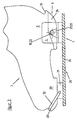
- the binding element 1 shown in Figure 1 is used for Locking the rear area 2 of a snowboard boot 3. It has a base plate 4, two of which are parallel mutually arranged side walls 5 are perpendicular in extend a distance that is the width of the Shoe sole 6 of the snowboard boot 3 in the rear area 2 corresponds. It is also possible to have the two side cheeks 5 not parallel to each other, but in one form the rear area 2 of a specific snowboard boot 3 to arrange the predetermined angle to each other.
- the bottom plate 4 and the side cheeks 5 of the binding element 1 are made of plastic and two Binding element halves 7a, 7b composed by Screws are connected.
- the outer corners 8 in the transition area from the base plate 4 to the side cheeks 5 are beveled.
- On the snowboard boot 3 facing inner sides of the side cheeks 5 and the top the base plate 4 is made of a reinforcing plate 9 Metal provided on which the bottom of the shoe sole 6 of the snowboard boot 3 rests in the locked state.
- the Total height of the base plate 4 with the reinforcement plate 9 is about 6 mm.
- At the upper inner ends are the side walls 5 and the reinforcing plate 9 with Inlet slopes 9a formed.
- the disks 13 On the sides facing away from the free ends 12 of the bolts 10 are the disks 13 each by a compression spring 15 acted upon.
- the coil springs 15 press the bolts as far out of the side walls 5 until the disks 13 on the shoulders between the holes 11 and the Cylinder rooms 14 abut. In this position the Bolt 10 a snowboard shoe 3 in the binding element 1 lock.
- the Bowden cables 16 are both bolts 10 connected together and into a spherical Pull lever 18 as an actuator for the unlocking device guided.
- a floor pull 16 of one Side cheek 5 through the base plate 4 into the other side cheek 5 out.
- the Bowden cables 16 radii as large as possible to be followed so that the unlocking mechanism is easy to is pressed.
- the openings 23 and the recesses 22 can also in a sole part 24 shown in FIGS. 4 and 5 be arranged in a simple manner by screwing in rear area of the shoe sole 6 can be attached.
- Conventional ski or snowboard boots 3 often have by default in the shoe soles 6 appropriately shaped Inserts that easily oppose an inventive Sole part 24 can be replaced.
- the sole part 24 a continuous between the two openings 23 Cavity 25, which has a larger diameter than the openings 23.
- Closure elements 26 axially slidably mounted Support each other via a compression spring 27. At her Outside the closure elements 26 each have one small paragraph 28, the openings 23 to the outside closes and thus the penetration of snow into the Openings 23 prevented. If the snowboard boot 3 in the Binding element 1 is locked, the closure elements 26 pressed inwards by the bolts 10. Therefore, the compression spring 27 has a lower spring stiffness than the springs 15.
- the front standard binding element is with the rear binding element 1 according to the invention by a Base plate 34 connected to the top of the Snowboards at the desired angle to the longitudinal axis of the Snowboards is attached.
- the rear protruding edge 35 of the shoe sole 6 is at the binding element 1 according to the invention not for Locking the snowboard boot 3 required. she allows However, the use of snowboard boot 3 also applies conventional standard snowboard bindings.
Landscapes
- Footwear And Its Accessory, Manufacturing Method And Apparatuses (AREA)
- Seal Device For Vehicle (AREA)
- Control Of Driving Devices And Active Controlling Of Vehicle (AREA)
- Cleaning Of Streets, Tracks, Or Beaches (AREA)
Description
- Figur 1:
- teilweise geschnittene Ansicht eines erfindungsgemäßen Bindungselementes
- Figur 2:
- Schnittansicht des Bindungselementes aus Figur 1 entlang der Schnittlinie A-A
- Figur 3:
- Seitenansicht einer kompletten Snowboardbindung mit Snowboardschuh
- Figur 4:
- Seitenansicht eines nachträglich an einen Standardsnowboardschuh montierbaren Sohlenteils
- Figur 5:
- Schnittansicht des Sohlenteils aus Figur 4 entlang der Schnittlinie B-B
Claims (13)
- Snowboardbindung mit einem mit dem Snowboard zu befestigenden Bindungselement, an dem ein Snowboard- oder Skischuh formschlüssig verriegelbar ist, und das zwei in einem der Breite der Sohle dieses Schuhes entsprechenden Abstand zueinander angeordneten, senkrecht zur Bodenplatte des Bindungselementes verlaufende Seitenwangen aufweist,
dadurch gekennzeichnet,
daß in jeder Seitenwange (5) mindestens ein vorstehendes Verriegelungselement (10), vorzugsweise ein Bolzen, zumindest annähernd parallel zur Bodenplatte (4) des Bindungselementes (1) gegen einen Kraftspeicher (15) verschiebbar gelagert ist, das an der der anderen Seitenwange (5) zugewandten Seite durch eine Öffnung (11) hindurchgeführt ist und geeignet ist, in eine Öffnung (23) oder Ausnehmung des Schuhes (3) einzugreifen oder einen Vorsprung des Schuhes (3) zu übergreifen. - Snowboardbindung nach Anspruch 1, dadurch gekennzeichnet, daß die Seitenwangen (5) an den der jeweils anderen Seitenwange (5) zugewandten Seiten oben eine Einlaufschräge (9a) aufweisen.
- Snowboardbindung nach Anspruch 1 oder 2,
dadurch gekennzeichnet, daß die Verriegelungselemente (10) zum freien Ende (12) hin an ihrer Oberseite abfallend abgeschrägt oder abgerundet sind. - Snowboardbindung nach einem der vorherigen Ansprüche, dadurch gekennzeichnet, daß die Verriegelungselemente (10) hydraulisch und/oder über mechanische Getriebe, vorzugsweise über einen Bowdenzug (16) gegen den Kraftspeicher (15) verschiebbar sind.
- Snowboardbindung nach einem der vorherigen Ansprüche, dadurch gekennzeichnet, daß die Verriegelungselemente (10) außen mit einer Kunststoffschicht ummantelt sind und/oder in den Seitenwangen in einer Führung aus Metall, vorzugsweise in einer Lagerbuchse mit eingearbeitetem Schmiermittel, gelagert sind.
- Snowboardbindung nach einem der vorherigen Ansprüche, dadurch gekennzeichnet, daß an den zur jeweils anderen Seitenwange (5) weisenden Seiten der Seitenwangen (5) je ein Vorsprung (21) angeordnet ist, der rund oder nach oben keilförmig zugespitzt ausgebildet ist und der geeignet ist, in eine entsprechend geformte Ausnehmung (22) des Snowboardschuhs (3) einzugreifen.
- Snowboardbindung nach einem der vorherigen Ansprüche, dadurch gekennzeichnet, daß das Bindungselement (1) zwischen den Seitenwangen (5) von einer Querkante nach vorne und/oder nach hinten schräg abfallend ausgebildet ist.
- Snowboardbindung nach einem der vorherigen Ansprüche, dadurch gekennzeichnet, daß das Bindungselement (1) derart ausgebildet ist, daß es den hinteren Bereich (2) des Snowboardschuhs (3) halten kann und daß auf einem Auftrittselement (31) durch einen Bügel (32) oder von einer oder zwei Haltenasen, die geeignet sind, ein bzw. zwei vorzugsweise seitlich am Snowboardschuh (3) vorstehende Vorsprünge zu übergreifen, der vordere Bereich (30) des Snowboardschuhs (3) gehalten ist.
- Snowboardbindung nach einem der Ansprüche 1 bis 7, dadurch gekennzeichnet, daß das Bindungselement (1) derart ausgebildet ist, daß es den mittleren Bereich des Snowboardschuhes (3) halten kann.
- Snowboardbindung nach Anspruch 8,
dadurch gekennzeichnet, daß das Bindungselement (1) und das Auftrittselement (31) zueinander verschiebbar an einer Grundplatte (34) befestigt sind. - Snowboardschuh für eine Snowboardbindung nach einem der vorherigen Ansprüche, wobei der Snowboardschuh an seinen Seiten in der Schuhsohle jeweils mindestens eine Ausnehmung hat, in die die Verriegelungselemente des Bindungselementes eingreifen können, dadurch gekennzeichnet, daß in den Ausnehmungen jeweils ein gegen einen Kraftspeicher (27) verschiebbares, vorzugsweise aus Kunststoff bestehendes Verschlußelement (26, 28) gelagert ist, das die Ausnehmung (23) nach außen abschließt und durch ein Verriegelungselement (10) nach innen verschiebbar ist.
- Snowboard- oder Skischuh mit einem in die Schuhsohle einsetzbaren Sohlenteil für eine Snowboardbindung nach einem der Ansprüche 1 bis 10, dadurch gekennzeichnet, daß das Sohlenteil (24) an seinen Seiten jeweils mindestens eine Ausnehmung (23) hat, in die die Verriegelungselemente (10) des Bindungselementes (1) eingreifen können und daß in den Ausnehmungen jeweils ein gegen einen Kraftspeicher (27) verschiebbares, vorzugsweise aus Kunststoff bestehendes Verschlußelement (26, 28) gelagert ist, das die Ausnehmung (23) nach außen abschließt und durch ein Verriegelungselement (10) nach innen verschiebbar ist.
- Snowboard- oder Skischuh nach Anspruch 11 oder 12, dadurch gekennzeichnet, daß in den Ausnehmungen (23) jeweils eine zur Aufnahme eines Verriegelungselementes (10) geeignete Metallbuchse vorgesehen ist.
Applications Claiming Priority (3)
| Application Number | Priority Date | Filing Date | Title |
|---|---|---|---|
| DE29608353U DE29608353U1 (de) | 1996-05-08 | 1996-05-08 | Automatische Snowboardbindung |
| DE29608353U | 1996-05-08 | ||
| PCT/EP1997/002348 WO1997041931A1 (de) | 1996-05-08 | 1997-05-07 | Automatische snowboardbindung |
Publications (2)
| Publication Number | Publication Date |
|---|---|
| EP0906142A1 EP0906142A1 (de) | 1999-04-07 |
| EP0906142B1 true EP0906142B1 (de) | 2000-03-29 |
Family
ID=8023713
Family Applications (1)
| Application Number | Title | Priority Date | Filing Date |
|---|---|---|---|
| EP97923012A Expired - Lifetime EP0906142B1 (de) | 1996-05-08 | 1997-05-07 | Automatische snowboardbindung |
Country Status (5)
| Country | Link |
|---|---|
| EP (1) | EP0906142B1 (de) |
| JP (1) | JP2000509310A (de) |
| AT (1) | ATE191155T1 (de) |
| DE (2) | DE29608353U1 (de) |
| WO (1) | WO1997041931A1 (de) |
Cited By (1)
| Publication number | Priority date | Publication date | Assignee | Title |
|---|---|---|---|---|
| NO20161100A1 (no) * | 2016-07-01 | 2018-01-02 | Rottefella As | Festemekanisme |
Families Citing this family (7)
| Publication number | Priority date | Publication date | Assignee | Title |
|---|---|---|---|---|
| AT405611B (de) * | 1996-08-09 | 1999-10-25 | Fancyform Design Engineering | Bindung und schuh für snowboards |
| AUPO531297A0 (en) * | 1997-02-25 | 1997-03-20 | Boulton Slider Pty Ltd | Snowboard binding attachment |
| FR2793155B1 (fr) | 1999-05-03 | 2001-06-22 | Look Fixations Sa | Fixation declenchable pour la planche de glisse |
| FR2822076B1 (fr) * | 2001-03-15 | 2003-06-13 | Salomon Sa | Ensemble de retenue d'un pied sur un engin destine a la pratique d'un sport |
| AT411018B (de) * | 2001-04-11 | 2003-09-25 | Fischer Gmbh | Skibindung für langlauf- und tourenski |
| DE202010000614U1 (de) | 2010-01-05 | 2011-05-26 | Salewa Sport Ag | Skischuh und Bindungssystem umfassend einen Skischuh und eine Skibindung |
| DE102015223117B4 (de) | 2015-11-23 | 2022-01-05 | Salewa Sport Ag | Tourenbindung mit einem Steuerkörper zur Begrenzung der Eindringtiefe |
Family Cites Families (5)
| Publication number | Priority date | Publication date | Assignee | Title |
|---|---|---|---|---|
| US3905613A (en) * | 1974-03-14 | 1975-09-16 | Calspan Corp | Ski binding |
| FR2351617A1 (fr) * | 1976-05-20 | 1977-12-16 | Salomon & Fils F | Chaussure de ski |
| FR2633842B1 (fr) * | 1988-07-07 | 1991-05-17 | Salomon Sa | Fixation de securite a interaction d'un pied sur l'autre pour surf de neige |
| DE3916233A1 (de) * | 1989-05-18 | 1990-11-22 | Hannes Marker | Sicherheitsbindung fuer snowboards |
| DE4416531C2 (de) * | 1994-05-06 | 1998-01-15 | F2 Int Gmbh | Snowboardbindung |
-
1996
- 1996-05-08 DE DE29608353U patent/DE29608353U1/de not_active Expired - Lifetime
-
1997
- 1997-05-07 EP EP97923012A patent/EP0906142B1/de not_active Expired - Lifetime
- 1997-05-07 WO PCT/EP1997/002348 patent/WO1997041931A1/de not_active Ceased
- 1997-05-07 DE DE59701370T patent/DE59701370D1/de not_active Expired - Fee Related
- 1997-05-07 JP JP9539548A patent/JP2000509310A/ja active Pending
- 1997-05-07 AT AT97923012T patent/ATE191155T1/de not_active IP Right Cessation
Cited By (2)
| Publication number | Priority date | Publication date | Assignee | Title |
|---|---|---|---|---|
| NO20161100A1 (no) * | 2016-07-01 | 2018-01-02 | Rottefella As | Festemekanisme |
| NO342268B1 (no) * | 2016-07-01 | 2018-04-30 | Rottefella As | Festemekanisme |
Also Published As
| Publication number | Publication date |
|---|---|
| DE29608353U1 (de) | 1996-07-18 |
| WO1997041931A1 (de) | 1997-11-13 |
| ATE191155T1 (de) | 2000-04-15 |
| JP2000509310A (ja) | 2000-07-25 |
| EP0906142A1 (de) | 1999-04-07 |
| DE59701370D1 (de) | 2000-05-04 |
Similar Documents
| Publication | Publication Date | Title |
|---|---|---|
| EP2659939B1 (de) | Ferseneinheit für eine Tourenskibindung | |
| EP2608853B1 (de) | Touren fersenbindung mit dynamischem gleitbereich | |
| EP0551899B1 (de) | Langlauf- oder Tourenskibindung für Langlaufskischuhe | |
| EP2762209B1 (de) | Fersenhalter mit Hilfshebel | |
| EP1379317B1 (de) | Einrichtung zur verbindung eines sportschuhes mit einer gleiteinrichtung | |
| EP2666525B1 (de) | Ferseneinheit mit Steighilfe und Bremsanordnung | |
| EP2626116A1 (de) | Vordereinheit für eine Gleitbrettbindung | |
| DE3310739A1 (de) | Bindungsanordnung zur festlegung eines skischuhes auf einem laufski mittels einer sicherheitsbindung | |
| DE2927059A1 (de) | Skischuh mit integrierter skibindung | |
| EP0365611A1 (de) | Schneegleiter | |
| DE102010043879A1 (de) | Tourenbindung mit Auslösemechanismus und Verriegelungsmechanismus | |
| EP1245254A2 (de) | Schi, insbesondere Alpinschi | |
| WO1984000498A1 (fr) | Fixation de securite pour skis | |
| EP3195906B1 (de) | Fersenautomat mit gehkonfiguration | |
| DE2812149A1 (de) | Skisicherheitsbindung | |
| DE102013224574B4 (de) | Ferseneinheit für eine Tourenbindung und Tourenbindung | |
| DE29608353U1 (de) | Automatische Snowboardbindung | |
| DE3405861C2 (de) | Langlauf- bzw. Wanderbindung | |
| AT397454B (de) | Skischuh | |
| CH706664B1 (de) | Skibindung. | |
| EP0877642B1 (de) | Bindung für snowboards | |
| DE69705804T2 (de) | Abstützungsplatte für Schuhe auf Skis | |
| EP3848099A1 (de) | Ferseneinheit mit steighilfe für eine tourenbindung | |
| DE102016014950A1 (de) | Verbesserte Fersenfreiheit für Tourenskibindung | |
| AT524641B1 (de) | Bremsanordnung für eine Gleitbrettbindung |
Legal Events
| Date | Code | Title | Description |
|---|---|---|---|
| PUAI | Public reference made under article 153(3) epc to a published international application that has entered the european phase |
Free format text: ORIGINAL CODE: 0009012 |
|
| 17P | Request for examination filed |
Effective date: 19981102 |
|
| AK | Designated contracting states |
Kind code of ref document: A1 Designated state(s): AT CH DE FR IT LI |
|
| 17Q | First examination report despatched |
Effective date: 19990511 |
|
| GRAG | Despatch of communication of intention to grant |
Free format text: ORIGINAL CODE: EPIDOS AGRA |
|
| GRAG | Despatch of communication of intention to grant |
Free format text: ORIGINAL CODE: EPIDOS AGRA |
|
| GRAH | Despatch of communication of intention to grant a patent |
Free format text: ORIGINAL CODE: EPIDOS IGRA |
|
| GRAH | Despatch of communication of intention to grant a patent |
Free format text: ORIGINAL CODE: EPIDOS IGRA |
|
| GRAA | (expected) grant |
Free format text: ORIGINAL CODE: 0009210 |
|
| AK | Designated contracting states |
Kind code of ref document: B1 Designated state(s): AT CH DE FR IT LI |
|
| REF | Corresponds to: |
Ref document number: 191155 Country of ref document: AT Date of ref document: 20000415 Kind code of ref document: T |
|
| REG | Reference to a national code |
Ref country code: CH Ref legal event code: NV Representative=s name: SCHMAUDER & PARTNER AG PATENTANWALTSBUERO Ref country code: CH Ref legal event code: EP |
|
| ET | Fr: translation filed | ||
| REF | Corresponds to: |
Ref document number: 59701370 Country of ref document: DE Date of ref document: 20000504 |
|
| ITF | It: translation for a ep patent filed | ||
| PLBE | No opposition filed within time limit |
Free format text: ORIGINAL CODE: 0009261 |
|
| STAA | Information on the status of an ep patent application or granted ep patent |
Free format text: STATUS: NO OPPOSITION FILED WITHIN TIME LIMIT |
|
| 26N | No opposition filed | ||
| PGFP | Annual fee paid to national office [announced via postgrant information from national office to epo] |
Ref country code: DE Payment date: 20050518 Year of fee payment: 9 |
|
| PGFP | Annual fee paid to national office [announced via postgrant information from national office to epo] |
Ref country code: FR Payment date: 20050519 Year of fee payment: 9 |
|
| PGFP | Annual fee paid to national office [announced via postgrant information from national office to epo] |
Ref country code: AT Payment date: 20050523 Year of fee payment: 9 |
|
| PGFP | Annual fee paid to national office [announced via postgrant information from national office to epo] |
Ref country code: CH Payment date: 20050524 Year of fee payment: 9 |
|
| PG25 | Lapsed in a contracting state [announced via postgrant information from national office to epo] |
Ref country code: AT Free format text: LAPSE BECAUSE OF NON-PAYMENT OF DUE FEES Effective date: 20060507 |
|
| PG25 | Lapsed in a contracting state [announced via postgrant information from national office to epo] |
Ref country code: LI Free format text: LAPSE BECAUSE OF NON-PAYMENT OF DUE FEES Effective date: 20060531 Ref country code: CH Free format text: LAPSE BECAUSE OF NON-PAYMENT OF DUE FEES Effective date: 20060531 |
|
| PGFP | Annual fee paid to national office [announced via postgrant information from national office to epo] |
Ref country code: IT Payment date: 20060531 Year of fee payment: 10 |
|
| PG25 | Lapsed in a contracting state [announced via postgrant information from national office to epo] |
Ref country code: DE Free format text: LAPSE BECAUSE OF NON-PAYMENT OF DUE FEES Effective date: 20061201 |
|
| REG | Reference to a national code |
Ref country code: CH Ref legal event code: PL |
|
| REG | Reference to a national code |
Ref country code: FR Ref legal event code: ST Effective date: 20070131 |
|
| PG25 | Lapsed in a contracting state [announced via postgrant information from national office to epo] |
Ref country code: FR Free format text: LAPSE BECAUSE OF NON-PAYMENT OF DUE FEES Effective date: 20060531 |
|
| PG25 | Lapsed in a contracting state [announced via postgrant information from national office to epo] |
Ref country code: IT Free format text: LAPSE BECAUSE OF NON-PAYMENT OF DUE FEES Effective date: 20070507 |