EP0905384A1 - Vorrichtung zum Zusammenbau zweier Rohre - Google Patents
Vorrichtung zum Zusammenbau zweier Rohre Download PDFInfo
- Publication number
- EP0905384A1 EP0905384A1 EP98402294A EP98402294A EP0905384A1 EP 0905384 A1 EP0905384 A1 EP 0905384A1 EP 98402294 A EP98402294 A EP 98402294A EP 98402294 A EP98402294 A EP 98402294A EP 0905384 A1 EP0905384 A1 EP 0905384A1
- Authority
- EP
- European Patent Office
- Prior art keywords
- tube
- base
- flat
- stirrups
- clamping
- Prior art date
- Legal status (The legal status is an assumption and is not a legal conclusion. Google has not performed a legal analysis and makes no representation as to the accuracy of the status listed.)
- Granted
Links
- 239000012530 fluid Substances 0.000 claims description 11
- 230000002285 radioactive effect Effects 0.000 claims description 4
- 230000008878 coupling Effects 0.000 abstract 1
- 238000010168 coupling process Methods 0.000 abstract 1
- 238000005859 coupling reaction Methods 0.000 abstract 1
- 238000013519 translation Methods 0.000 description 10
- 230000014616 translation Effects 0.000 description 10
- 210000004027 cell Anatomy 0.000 description 2
- 230000000295 complement effect Effects 0.000 description 1
- 230000006835 compression Effects 0.000 description 1
- 238000007906 compression Methods 0.000 description 1
- 230000001143 conditioned effect Effects 0.000 description 1
- 239000002826 coolant Substances 0.000 description 1
- 238000005553 drilling Methods 0.000 description 1
- 230000005489 elastic deformation Effects 0.000 description 1
- 238000009434 installation Methods 0.000 description 1
- 238000000034 method Methods 0.000 description 1
- 238000000926 separation method Methods 0.000 description 1
Images


Classifications
-
- F—MECHANICAL ENGINEERING; LIGHTING; HEATING; WEAPONS; BLASTING
- F16—ENGINEERING ELEMENTS AND UNITS; GENERAL MEASURES FOR PRODUCING AND MAINTAINING EFFECTIVE FUNCTIONING OF MACHINES OR INSTALLATIONS; THERMAL INSULATION IN GENERAL
- F16B—DEVICES FOR FASTENING OR SECURING CONSTRUCTIONAL ELEMENTS OR MACHINE PARTS TOGETHER, e.g. NAILS, BOLTS, CIRCLIPS, CLAMPS, CLIPS OR WEDGES; JOINTS OR JOINTING
- F16B7/00—Connections of rods or tubes, e.g. of non-circular section, mutually, including resilient connections
- F16B7/04—Clamping or clipping connections
- F16B7/044—Clamping or clipping connections for rods or tubes being in angled relationship
- F16B7/048—Clamping or clipping connections for rods or tubes being in angled relationship for rods or for tubes without using the innerside thereof
- F16B7/0493—Clamping or clipping connections for rods or tubes being in angled relationship for rods or for tubes without using the innerside thereof forming a crossed-over connection
-
- F—MECHANICAL ENGINEERING; LIGHTING; HEATING; WEAPONS; BLASTING
- F16—ENGINEERING ELEMENTS AND UNITS; GENERAL MEASURES FOR PRODUCING AND MAINTAINING EFFECTIVE FUNCTIONING OF MACHINES OR INSTALLATIONS; THERMAL INSULATION IN GENERAL
- F16L—PIPES; JOINTS OR FITTINGS FOR PIPES; SUPPORTS FOR PIPES, CABLES OR PROTECTIVE TUBING; MEANS FOR THERMAL INSULATION IN GENERAL
- F16L3/00—Supports for pipes, cables or protective tubing, e.g. hangers, holders, clamps, cleats, clips, brackets
- F16L3/08—Supports for pipes, cables or protective tubing, e.g. hangers, holders, clamps, cleats, clips, brackets substantially surrounding the pipe, cable or protective tubing
- F16L3/085—Supports for pipes, cables or protective tubing, e.g. hangers, holders, clamps, cleats, clips, brackets substantially surrounding the pipe, cable or protective tubing for pipes being in an angled relationship to each other
-
- F—MECHANICAL ENGINEERING; LIGHTING; HEATING; WEAPONS; BLASTING
- F16—ENGINEERING ELEMENTS AND UNITS; GENERAL MEASURES FOR PRODUCING AND MAINTAINING EFFECTIVE FUNCTIONING OF MACHINES OR INSTALLATIONS; THERMAL INSULATION IN GENERAL
- F16L—PIPES; JOINTS OR FITTINGS FOR PIPES; SUPPORTS FOR PIPES, CABLES OR PROTECTIVE TUBING; MEANS FOR THERMAL INSULATION IN GENERAL
- F16L3/00—Supports for pipes, cables or protective tubing, e.g. hangers, holders, clamps, cleats, clips, brackets
- F16L3/01—Supports for pipes, cables or protective tubing, e.g. hangers, holders, clamps, cleats, clips, brackets for supporting or guiding the pipes, cables or protective tubing, between relatively movable points, e.g. movable channels
- F16L3/015—Supports for pipes, cables or protective tubing, e.g. hangers, holders, clamps, cleats, clips, brackets for supporting or guiding the pipes, cables or protective tubing, between relatively movable points, e.g. movable channels using articulated- or supple-guiding elements
-
- F—MECHANICAL ENGINEERING; LIGHTING; HEATING; WEAPONS; BLASTING
- F16—ENGINEERING ELEMENTS AND UNITS; GENERAL MEASURES FOR PRODUCING AND MAINTAINING EFFECTIVE FUNCTIONING OF MACHINES OR INSTALLATIONS; THERMAL INSULATION IN GENERAL
- F16L—PIPES; JOINTS OR FITTINGS FOR PIPES; SUPPORTS FOR PIPES, CABLES OR PROTECTIVE TUBING; MEANS FOR THERMAL INSULATION IN GENERAL
- F16L3/00—Supports for pipes, cables or protective tubing, e.g. hangers, holders, clamps, cleats, clips, brackets
- F16L3/08—Supports for pipes, cables or protective tubing, e.g. hangers, holders, clamps, cleats, clips, brackets substantially surrounding the pipe, cable or protective tubing
- F16L3/12—Supports for pipes, cables or protective tubing, e.g. hangers, holders, clamps, cleats, clips, brackets substantially surrounding the pipe, cable or protective tubing comprising a member substantially surrounding the pipe, cable or protective tubing
- F16L3/1211—Supports for pipes, cables or protective tubing, e.g. hangers, holders, clamps, cleats, clips, brackets substantially surrounding the pipe, cable or protective tubing comprising a member substantially surrounding the pipe, cable or protective tubing with a substantially-radial tightening or securing member
-
- F—MECHANICAL ENGINEERING; LIGHTING; HEATING; WEAPONS; BLASTING
- F16—ENGINEERING ELEMENTS AND UNITS; GENERAL MEASURES FOR PRODUCING AND MAINTAINING EFFECTIVE FUNCTIONING OF MACHINES OR INSTALLATIONS; THERMAL INSULATION IN GENERAL
- F16L—PIPES; JOINTS OR FITTINGS FOR PIPES; SUPPORTS FOR PIPES, CABLES OR PROTECTIVE TUBING; MEANS FOR THERMAL INSULATION IN GENERAL
- F16L55/00—Devices or appurtenances for use in, or in connection with, pipes or pipe systems
- F16L55/02—Energy absorbers; Noise absorbers
-
- Y—GENERAL TAGGING OF NEW TECHNOLOGICAL DEVELOPMENTS; GENERAL TAGGING OF CROSS-SECTIONAL TECHNOLOGIES SPANNING OVER SEVERAL SECTIONS OF THE IPC; TECHNICAL SUBJECTS COVERED BY FORMER USPC CROSS-REFERENCE ART COLLECTIONS [XRACs] AND DIGESTS
- Y10—TECHNICAL SUBJECTS COVERED BY FORMER USPC
- Y10T—TECHNICAL SUBJECTS COVERED BY FORMER US CLASSIFICATION
- Y10T403/00—Joints and connections
- Y10T403/71—Rod side to plate or side
- Y10T403/7105—Connected by double clamp
-
- Y—GENERAL TAGGING OF NEW TECHNOLOGICAL DEVELOPMENTS; GENERAL TAGGING OF CROSS-SECTIONAL TECHNOLOGIES SPANNING OVER SEVERAL SECTIONS OF THE IPC; TECHNICAL SUBJECTS COVERED BY FORMER USPC CROSS-REFERENCE ART COLLECTIONS [XRACs] AND DIGESTS
- Y10—TECHNICAL SUBJECTS COVERED BY FORMER USPC
- Y10T—TECHNICAL SUBJECTS COVERED BY FORMER US CLASSIFICATION
- Y10T403/00—Joints and connections
- Y10T403/71—Rod side to plate or side
- Y10T403/7182—Yoke or ring-type connector
-
- Y—GENERAL TAGGING OF NEW TECHNOLOGICAL DEVELOPMENTS; GENERAL TAGGING OF CROSS-SECTIONAL TECHNOLOGIES SPANNING OVER SEVERAL SECTIONS OF THE IPC; TECHNICAL SUBJECTS COVERED BY FORMER USPC CROSS-REFERENCE ART COLLECTIONS [XRACs] AND DIGESTS
- Y10—TECHNICAL SUBJECTS COVERED BY FORMER USPC
- Y10T—TECHNICAL SUBJECTS COVERED BY FORMER US CLASSIFICATION
- Y10T403/00—Joints and connections
- Y10T403/71—Rod side to plate or side
- Y10T403/7194—Crossed rods
Definitions
- the invention relates to an assembly device between a first tube of circular section of axis X serving as support and a second tube forming a supported piping, of circular section of axis Y, these two tubes being placed substantially 90 ° from each other.
- the invention relates to a device allowing to attach a tube arranged horizontally or inclined, this tube constituting a pipe in which a fluid circulates, such as a fluid coolant or a radioactive fluid, on a support arranged substantially at 90 ° to the tube, this support preferably being arranged horizontally.
- a fluid circulates such as a fluid coolant or a radioactive fluid
- the pipes being intended in particular for circulation of utility fluids such as heat transfer fluids and / or fluids radioactive in nuclear facilities for example it is necessary that the assembly device shows a particularly good earthquake resistance, which it allows fixing between a support element and tubes of different diameter and that the assembly of said assembly device is the easiest and safest possible.
- An object of the present invention is to provide a device assembly which has good earthquake resistance, which is easy to assemble and which allows the assembly between two elements having a section of different dimension.
- tubular supports reinforces the symmetry of the mounting between the support and the piping and allows to tilt at will the piping around its support.
- said first means of link include at least one stirrup having a flat U-shaped hoop partially surrounding one of the tubes and the ends of which are in contact or at proximity of the base and a clamping hoop enclosing said flat hoop on all its outer contour, each end of said clamping arc passing through said base through one of said holes and having means for clamping said clamping hoop relative to said flat hoop and said second means of link include at least one flat collar each end of which is fixed at the base at one of said holes by means of the corresponding end of said clamping arch.
- each of the ends of the flat collar forms a connecting tab which includes an opening intended to be arranged opposite a hole in the base.
- the clamping means of the clamping arch of the first connecting means comprises threads intended to pass through the base through holes and to cooperate with nuts Tightening.
- this preferred embodiment leads to a symmetrical structure allowing a better fixing of the whole, that it exists then a possibility of having or not having a tightening of the different elements during mounting as well as a possibility to vary the inclination of the device assembly according to the slope of the piping and / or support.
- the assembly device is used to support pipes on a horizontal support but we understand that the device assembly according to the invention also allows other configurations such as the assembly of horizontal or slightly inclined piping (the angle tilt, for example 2 °) on a support tube arranged vertically or well an assembly between a pipe and a support tube forming between them a plan having any orientation, provided that the piping and the tube support form between them an angle substantially equal to 90 °.
- the angle tilt for example 2 °
- the assembly device according to the present invention is advantageously, but not exclusively, used to assemble pipes, intended for circulation of utility fluids and / or radioactive fluids in a gallery or nuclear industry cell, with tubular support elements.
- the assembly device can be produced according to the invention, so that it allows a relative translational movement between supported piping and support tube (longitudinal, transverse guidance or two at a time), i.e. a total blockage between supported piping and support tube.
- the dimensions of the arch are modified flat, these condition the existence or not of the clamping of the stirrup around the tube (support or piping supported): a flat hoop with more dimensions important that the diameter of the surrounded tube creates a play and allows a freedom of movement of the tube surrounded by the stirrup comprising this flat arch.
- an additional piece or wedge is then provided which moves the bottom of the collar away flat of the base and creates a clearance between the base and the tube surrounded by this flat collar.
- a device assembly 10 of the invention allows two tubes to be assembled together, possibly different diameters, placed approximately 90 ° from each other: a first tube 14 of axis X, constituting the support tube is connected to a second tube 12, of axis Y, constituting the supported piping.
- these two tubes 12 and 14 are placed horizontally but it is perfectly conceivable that the two axes X and Y can present any other orientation without the assembly device 10 is modified.
- the assembly device 10 comprises a parallelepiped base 16 rectangular with four holes 18; this base 16 having its length and its width respectively parallel to the Y and X axes of the tubes and being placed between the piping 12 and the support tube 14.
- the assembly device 10 comprises also two stirrups 20 each surrounding a section of the piping 12 and two flat collars 22 each surrounding a section of the support tube 14, the ends brackets and flat collars being connected to each other and to the base by means of the holes 18 as will be described in more detail below.
- Each stirrup 20 consists, on the one hand, of a hoop of clamping 24 with circular section constituting a jumper intended to surround a section of one of the tubes and whose ends 24a, straight and threaded, are intended to cross two of the holes 18 of the base 16 and cooperate with nuts clamping 28 and, on the other hand, a flat hoop 26 constituting a fur disposed between the tube and the clamping arch 24.
- the tube 12 has a large diameter D1 equal to the distance separating the straight branches of the U from the flat arch 26. Said diameter D1 is greater than the distance between the ends 26a of the arch flat 26 of the bottom of the U.
- a section of the external surface of the tube 12, the cross section of which constitutes the upper semicircle of the tube 12, is in contact with the interior of the flat arch 26, in the upper part of the flat arch 26 forming the base U rounded.
- the lower part of the tube 12 is in contact with the base 16, shown in dotted lines in FIG. 2A, along a portion of generator of the tube 12.
- the tube 12 is blocked by the stirrup 20, the fixing of which is carried out by mounting the clamping nuts 28 on the threaded ends 24a of the clamping arch 24, the nuts 28 being tightened to block said tube 12 between the base 16 and the stirrup 20; the straight branches of the U of the flat arch 26 being of such a length that their ends 26a are not in contact with the base 16.
- the diameter D0 of the tube 12 is (smaller than D1) smaller than the distance separating the ends 26a of the flat arch 26 from the bottom of the U.
- the bracket 20 by tightening the nuts 28 on the threaded ends 24a of the hoop tightening 24, there is a limit position corresponding to the moment when the ends 26a of the flat arch 26 come into contact with the base 16 so that the nuts 28 are blocked and that the tube 12 is not tightly mounted in the stirrup 20 since there is a clearance between said tube 12 (of outside diameter D0) and the flat arch 26.
- the play is present at both between the tube 12 and the straight branches of the flat arch 26, and between the tube 12 and the assembly constituted by the base 16 and the rounded base of the U of the flat arch.
- the tightening of the bracket 20 on the tube which it surrounds is conditioned by the dimensions of the hoop flat 26, i.e. the diameter of the rounded base of the U, on the one hand, and the length branches of the U, on the other hand, depending on the diameter of the tube, so that the flat bar 26 transmits or not the tightening of the clamping bar to the tube concerned 24 arranged around said tube.
- the flat arch 26 constitutes a fur of protection of the tube since it prevents deformation of the external surface of the tube which is in contact with the stirrup 20, by distributing the compression forces generated by the clamping arch 24, on a portion of the periphery of a section of tube corresponding to the width of the flat arch 26.
- FIGS. 2A and 2'A show, two possible diameters (respectively D1 and D0, with D1> D0) for the tube 12, supported piping or support tube. It is obvious that we adapt, in the practical, the dimensions of the first connecting means to that of the tube 12 concerned and not vice versa.
- stirrup 20 comprising a flat arch 26 of suitable length and diameter, it is possible to provide a tight mounting of the tube in the bracket 20 so that this tube has no degree of freedom or else provide a larger flat bar 26 which allows a certain play between the tube and the bracket 20 so that this tube can slide in the bracket which gives it a degree of freedom in translation along its own axis.
- the proposed assembly device 10 preferably comprises (as shown in the appended figures), two stirrups 20 and two flat collars 22 arranged so as to form a symmetrical assembly with respect to the planes (X, Z) and (Y, Z); the axes X, Y, Z being orthogonal to each other.
- the median planes of each pair of necklaces 22 or stirrups 20 are separated one of the other by a distance greater than the diameter of the tube that this couple does not surround.
- FIGS. 3A and 3B illustrate a first embodiment of the assembly device according to the invention in which a degree of freedom to the supported piping which can move in translation according to its own Y-axis, which generates longitudinal guidance of the supported piping 12 by stirrup 20.
- This first embodiment of the assembly device is characterized in that the stirrups 20 surround the second tube 12 (piping supported), in that the arches 26 of said stirrups 20 are dimensioned so that when their ends 26a are in contact with the base 16, the second tube 12 can slide in said stirrups 20, and in that the collars 22, surrounding the first tube 14 (support), are shaped so that when their connecting lugs 22b are pressed against the base 16, by the clamping nuts 28 mounted on the threaded ends 24a of the clamping arches 24, said first tube 14 is blocked.
- the flat collars 22 have a U-shaped central portion 22a at the ends of which are connected, preferably substantially 90 °, connecting lugs 22b, preferably rectangular and flat.
- This definition of shape of the flat necklaces 22 is valid for the whole of this description in which is summed up by the definition " ⁇ -shaped".
- the length and the diameter of the part central 22a in the shape of a U are provided to tightly surround a tube.
- the connecting lugs 22b flat collars 22 are provided with an opening 23 placed in the extension of the holes 18 of the base 16 so that each end 24a of a clamping arch 24 successively passes through a hole 18 then an opening 23, a clamping nut 28 being mounted on the thread of the end 24a coming in contact against the rear face of the connecting lug 22b, the front face of this lug link 22b being in contact against the base 16.
- the stirrups 20, on the one hand, and the clamps 22, on the other hand are mounted two by two parallel, the two stirrups being crossed with respect to the two collars and cooperating with each other at the through four holes 18.
- the brackets 20 surround, without tightening it, the supported piping 12 and the two flat collars 22 enclose the support tube 14.
- FIGS. 4A and 4B illustrate the second embodiment of the assembly device 10 according to the invention.
- This second embodiment of the assembly device is characterized in that the stirrups 20 surround the first tube 14 (support), in that that the flat arches 26 of said stirrups 20 are dimensioned so that when their ends 26a are in contact with the base 16, the first tube 14 can slide in said stirrups 20, and in that the collars 22, surrounding the second tube 12 (supported piping), are shaped so that when their legs link 22b are pressed against the base 16, by the tightening nuts 28 mounted on the threaded ends 24a of the clamping arches 24, the second tube 12 is blocked.
- the support tube 14 is in contact against the base 16 in the case illustrated in FIGS. 4A and 4B since the fixed assembly comprising the supported piping 12, the flat collars 22 and the base 16 is supported on the support tube 14 which is under the piping 12. From in this way, the assembly device 10 remains integral with the piping supported 12, this assembly being able to move in the direction of the X axis on the support tube 14.
- FIGS. 5A and 5B illustrate a third embodiment of the assembly device 10 according to the invention in which one seeks to obtain for the piping supported 12 two degrees of freedom corresponding to two translations, respectively in parallel directions to the X and Y axes.
- This third embodiment is obtained from the assembly corresponding to the first or second embodiment (the case Figure illustrated in Figures 5A and 5B follows from the first form of realization but we could also start from the assembly corresponding to the second embodiment) in which a shim 30 pierced between is added the connecting lugs 22b of each collar 22 and the base 16, the drilling of this wedge 30 being positioned to be placed, during assembly, facing and in the extension of the opening 23 with a connecting lug 22b and a hole 18 in the base 16.
- This third embodiment of the assembly device is characterized in that the stirrups 20 surround the second tube 12 (piping supported), in that it further comprises a shim 30 pierced interposed between each connecting lug 22b of said flat collars 22 and the base 16 and crossed by the threaded ends 24a of the clamping hoops, so that when the first tube 14 (support) is pressed against the bottom of the flat collar 22, there is a set of mounting between said first tube 14 and base 16 allowing sliding of the device 10 along the first tube 14 (support) and in that the flat arches 26 said stirrups 20 are dimensioned so that when their ends 26a are in contact with the base 16, the second tube 12 can slide in said calipers 20.
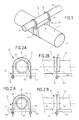
- FIGS 6A and 6B illustrate the fourth embodiment of the assembly device according to the invention.
- This fourth embodiment of the assembly device is characterized in that the stirrups 20 surround the second tube 12 (supported piping), in that the flat arches 26 of said stirrups 20 are dimensioned so that when their ends 26a are close to or in contact with the base 16, the second tube 12 is blocked by said stirrups 20, and in that the collars 22, surrounding the first tube 14 (support), are shaped so that when their legs link 22b are pressed against the base 16, by the tightening nuts 28 mounted on the threaded ends 24a of the clamping arches, the first tube 14 (support) is blocked.
- This fourth embodiment of the invention provides a assembly device granting no degree of freedom to the piping supported 12 so that one obtains a blocked support for pipes blocked.
- the stirrups 20 surround the supported piping 12 and flat collars 22 enclose the support tube 14 but could reverse the relative position of the stirrups 20 and the flat collars 22 on the tubes.
- the flat collars 22 can have other shapes than that described above, that is to say in the form of ⁇ . So, using, for example, a generally rectangular base with four corners protrusions crossed by holes oriented in a direction belonging to the plane (X, Y), this allows the use of flat U-shaped collars rather than form of ⁇ .
- the supported piping 12 has a smaller diameter than that of the support tube 14 but it is quite understandable that the tubes 12 and 14 have a substantially equal diameter or else that the diameter of the supported piping is larger than that of the support tube. So we understand that, without departing from the scope of the present invention, all combinations of diameters, of the support tube 14 and of the piping 12, are possible.
Landscapes
- Engineering & Computer Science (AREA)
- General Engineering & Computer Science (AREA)
- Mechanical Engineering (AREA)
- Supports For Pipes And Cables (AREA)
- Mutual Connection Of Rods And Tubes (AREA)
- Quick-Acting Or Multi-Walled Pipe Joints (AREA)
Applications Claiming Priority (2)
| Application Number | Priority Date | Filing Date | Title |
|---|---|---|---|
| FR9711630 | 1997-09-18 | ||
| FR9711630A FR2768473B1 (fr) | 1997-09-18 | 1997-09-18 | Dispositif d'assemblage entre deux tubes |
Publications (2)
| Publication Number | Publication Date |
|---|---|
| EP0905384A1 true EP0905384A1 (de) | 1999-03-31 |
| EP0905384B1 EP0905384B1 (de) | 2003-11-19 |
Family
ID=9511221
Family Applications (1)
| Application Number | Title | Priority Date | Filing Date |
|---|---|---|---|
| EP98402294A Expired - Lifetime EP0905384B1 (de) | 1997-09-18 | 1998-09-17 | Vorrichtung zum Zusammenbau zweier Rohre |
Country Status (7)
| Country | Link |
|---|---|
| US (1) | US6227757B1 (de) |
| EP (1) | EP0905384B1 (de) |
| JP (1) | JP4105810B2 (de) |
| KR (1) | KR100573980B1 (de) |
| CA (1) | CA2246986C (de) |
| DE (1) | DE69819838T2 (de) |
| FR (1) | FR2768473B1 (de) |
Cited By (1)
| Publication number | Priority date | Publication date | Assignee | Title |
|---|---|---|---|---|
| KR100573980B1 (ko) * | 1997-09-18 | 2007-05-17 | 꼬게마 꽁빠니 제네랄 데 마띠에르 뉘끌레르 | 2개의튜브를함께연결하는연결장치 |
Families Citing this family (32)
| Publication number | Priority date | Publication date | Assignee | Title |
|---|---|---|---|---|
| FR2768485B1 (fr) | 1997-09-18 | 1999-12-10 | Cogema | Systeme de supportage pour tuyauteries en galeries techniques, notamment de l'industrie nucleaire |
| US6347904B1 (en) * | 1998-04-14 | 2002-02-19 | George Stuart Knighton | Fly clamp for reinforcing bars in concrete construction |
| US6663134B2 (en) * | 2002-01-31 | 2003-12-16 | Case, Llc | Planter hitch apparatus |
| US6925962B2 (en) * | 2003-09-19 | 2005-08-09 | Norbco, Inc. | Elevated beam cow stall assembly |
| US20050121559A1 (en) * | 2003-12-09 | 2005-06-09 | King Robert W. | Simplified pipe support assembly |
| US7654048B2 (en) * | 2005-06-13 | 2010-02-02 | Sukup Manufacturing Co. | Grain bin roof ring mounting bracket |
| US7523895B1 (en) * | 2006-06-01 | 2009-04-28 | Automatic Fire Control, Incorporated | Sway brace and method for securing a pipe or conduit against sway |
| US7516922B1 (en) | 2006-11-03 | 2009-04-14 | Automatic Fire Control, Incorporated | Sway brace and method for securing a pipe or conduit against sway |
| US7726634B2 (en) * | 2006-12-07 | 2010-06-01 | Newport News Shipbuilding And Dry Dock Company | System and method for tensioning and locking a safety strand |
| US20080185565A1 (en) * | 2007-02-06 | 2008-08-07 | C.E. Shepherd Co., Inc. | Fence and installation method therefor |
| WO2009094302A2 (en) * | 2008-01-21 | 2009-07-30 | Erico International Corporation | Universal structural attachment for seismic brace |
| US8353486B2 (en) * | 2008-01-21 | 2013-01-15 | Erico International Corporation | Lateral seismic brace |
| KR20100002359U (ko) * | 2008-08-26 | 2010-03-08 | 정순학 | 비닐하우스용 파이프 고정구 |
| US8070113B1 (en) * | 2009-03-30 | 2011-12-06 | Automatic Fire Control, Incorporated | Sway brace |
| WO2011048704A1 (ja) * | 2009-10-21 | 2011-04-28 | Thubota Kunihiro | ダンパー形式の減衰機構を備えた免震装置 |
| DE102009047149A1 (de) * | 2009-11-25 | 2011-05-26 | Hünnebeck Group GmbH | Anschlusselement und teleskopierbares Vertikalrohr mit demselben |
| US8800938B2 (en) * | 2011-09-21 | 2014-08-12 | Cooper B-Line, Inc. | Pipe-to-pipe brace assembly |
| US9629770B1 (en) | 2011-12-19 | 2017-04-25 | Joseph T. Dyer | Portable transfer board and method |
| US20140299721A1 (en) * | 2013-04-05 | 2014-10-09 | Tomasz Habrzyk | Hose Clamp Brace |
| US9052038B2 (en) * | 2013-06-13 | 2015-06-09 | Mueller International, Llc | Sway brace retaining clip |
| CN103541954A (zh) * | 2013-11-13 | 2014-01-29 | 李明科 | 一种双向式水平连接块 |
| KR101879413B1 (ko) * | 2016-07-18 | 2018-07-18 | 한국해양과학기술원 | 액화가스 저장용기 시험장치 |
| CN107380133A (zh) * | 2017-09-05 | 2017-11-24 | 东莞市北扬工业设计有限公司 | 一种货运车厢清洗机器人上的喷管固定装置 |
| JP7240852B2 (ja) * | 2017-11-08 | 2023-03-16 | イートン インテリジェント パワー リミテッド | 建物内の非構造部品用耐震クランプ |
| US10851917B2 (en) * | 2017-11-08 | 2020-12-01 | Eaton Intelligent Power Limited | Seismic clamp for non-structural components in a building |
| CN109599201B (zh) * | 2018-10-31 | 2021-11-16 | 中国核电工程有限公司 | 一种核电站主给水廊道区布置方法 |
| CN111355441A (zh) * | 2018-12-24 | 2020-06-30 | 中国电子科技集团公司第四十八研究所 | 一种用于通信铁塔的光伏支架 |
| JP7253926B2 (ja) * | 2019-01-09 | 2023-04-07 | Awj株式会社 | 配管支持具及びその製造方法 |
| CN110630818B (zh) * | 2019-10-09 | 2023-12-05 | 张家港派赛格汽车部件有限公司 | 一种汽车管道支撑环结构及其凸包加工装置、使用方法 |
| AU2022335261A1 (en) | 2021-08-24 | 2024-02-08 | Concealfab, Inc. | Low-pim dual pipe clamp for cellular base station antenna sites |
| CN113622650B (zh) * | 2021-09-07 | 2023-04-14 | 无锡市第五建筑工程有限公司 | 一种建筑用抗震手脚架 |
| USD992407S1 (en) * | 2022-06-01 | 2023-07-18 | Concealfab, Inc. | Dual pipe clamp |
Citations (4)
| Publication number | Priority date | Publication date | Assignee | Title |
|---|---|---|---|---|
| FR1091746A (fr) * | 1953-09-19 | 1955-04-14 | Entpr & De Pose Pour Tous Prod | Raccord de jonction pour tubes et barres |
| FR1125029A (fr) * | 1955-04-20 | 1956-10-23 | Cie Generale D Utilisation Des | Dispositif d'accouplement pour tubes et autres pièces cylindriques |
| GB2120310A (en) * | 1982-05-18 | 1983-11-30 | Stromberg Greest Ltd | Aerial Clamp |
| GB2241735A (en) * | 1990-02-16 | 1991-09-11 | Bicc Plc | Joints in piling reinforcement |
Family Cites Families (27)
| Publication number | Priority date | Publication date | Assignee | Title |
|---|---|---|---|---|
| US2215283A (en) | 1938-07-06 | 1940-09-17 | Adel Prec Products Corp | Line supporting clip |
| US2352145A (en) | 1944-03-11 | 1944-06-20 | Cletus P Wright | Preinsulated pipe hanger unit |
| US2655088A (en) * | 1949-07-06 | 1953-10-13 | Allis Chalmers Mfg Co | Tool mounting |
| US2906294A (en) | 1953-11-27 | 1959-09-29 | Earl C Peterson | Duct structure for pipes |
| US2894773A (en) * | 1956-06-12 | 1959-07-14 | Kidde Textile Machinery Corp | Clamp |
| US3370815A (en) | 1965-09-13 | 1968-02-27 | Lamb Co F Jos | Shock absorbing pad for conduit clamping device |
| US3787016A (en) | 1972-04-20 | 1974-01-22 | C Laval | Rack for supporting cables and the like |
| GB1404643A (en) | 1972-09-23 | 1975-09-03 | Clarke Chapman Ltd | Heat exchanger |
| US3761600A (en) | 1973-01-11 | 1973-09-25 | Ite Imperial Corp | Above ground gas-insulated pipe type transmission configuration |
| JPS50713U (de) * | 1973-05-01 | 1975-01-07 | ||
| JPS5248223A (en) * | 1975-10-15 | 1977-04-16 | Yoshiharu Shimizu | Connection device of pipe* etc* |
| US4032246A (en) * | 1976-05-10 | 1977-06-28 | Visi-Trol Engineering Company | Clamp |
| US4126012A (en) | 1976-07-15 | 1978-11-21 | James W. Green | Method and apparatus for supporting pipe in filled dirt |
| US4115966A (en) * | 1977-02-14 | 1978-09-26 | Delee Barry | Clamping device for display structures |
| US4146203A (en) | 1977-10-20 | 1979-03-27 | Williams Robert O | Pipe hanger supports |
| DE2816678C3 (de) | 1978-04-18 | 1980-10-23 | Neuwalzwerk Bettermann Ohg, 5750 Menden | Kabelträgersystem |
| SE420664B (sv) | 1981-01-08 | 1981-10-19 | Owe Gothberg | Berlist av plastmaterial med i huvudsak u-formad tversektionsform for uppberning av rorledningar, kablar etc |
| US4530478A (en) | 1982-05-06 | 1985-07-23 | Pipe Shields, Inc. | Insulating pipe support apparatus |
| US4516296A (en) * | 1983-10-05 | 1985-05-14 | Zsi, Inc. | Tubing clamp and method of making the same |
| US4718459A (en) | 1986-02-13 | 1988-01-12 | Exxon Production Research Company | Underwater cryogenic pipeline system |
| US5102073A (en) | 1986-12-18 | 1992-04-07 | Atlantic Richfield Company | Freestanding concrete pipe support |
| US5039039A (en) | 1990-01-04 | 1991-08-13 | Schaffer Michael D | Hanger bracket |
| NL9000142A (nl) * | 1990-01-19 | 1991-08-16 | Johannes Martinus Willibrordus | Ligboxafscheiding. |
| JPH043543U (de) * | 1990-04-26 | 1992-01-13 | ||
| US5215281A (en) * | 1991-09-27 | 1993-06-01 | Zsi, Inc. | Two-piece cushion insert for U-bolt clamp assembly |
| US5961248A (en) * | 1997-04-18 | 1999-10-05 | Tourtellotte; Mills C. | Structural member connection and method |
| FR2768473B1 (fr) * | 1997-09-18 | 1999-12-03 | Cogema | Dispositif d'assemblage entre deux tubes |
-
1997
- 1997-09-18 FR FR9711630A patent/FR2768473B1/fr not_active Expired - Fee Related
-
1998
- 1998-09-14 US US09/151,815 patent/US6227757B1/en not_active Expired - Fee Related
- 1998-09-14 CA CA002246986A patent/CA2246986C/en not_active Expired - Fee Related
- 1998-09-16 KR KR1019980038192A patent/KR100573980B1/ko not_active IP Right Cessation
- 1998-09-17 DE DE69819838T patent/DE69819838T2/de not_active Expired - Lifetime
- 1998-09-17 EP EP98402294A patent/EP0905384B1/de not_active Expired - Lifetime
- 1998-09-18 JP JP26544898A patent/JP4105810B2/ja not_active Expired - Fee Related
Patent Citations (4)
| Publication number | Priority date | Publication date | Assignee | Title |
|---|---|---|---|---|
| FR1091746A (fr) * | 1953-09-19 | 1955-04-14 | Entpr & De Pose Pour Tous Prod | Raccord de jonction pour tubes et barres |
| FR1125029A (fr) * | 1955-04-20 | 1956-10-23 | Cie Generale D Utilisation Des | Dispositif d'accouplement pour tubes et autres pièces cylindriques |
| GB2120310A (en) * | 1982-05-18 | 1983-11-30 | Stromberg Greest Ltd | Aerial Clamp |
| GB2241735A (en) * | 1990-02-16 | 1991-09-11 | Bicc Plc | Joints in piling reinforcement |
Cited By (1)
| Publication number | Priority date | Publication date | Assignee | Title |
|---|---|---|---|---|
| KR100573980B1 (ko) * | 1997-09-18 | 2007-05-17 | 꼬게마 꽁빠니 제네랄 데 마띠에르 뉘끌레르 | 2개의튜브를함께연결하는연결장치 |
Also Published As
| Publication number | Publication date |
|---|---|
| JP4105810B2 (ja) | 2008-06-25 |
| FR2768473B1 (fr) | 1999-12-03 |
| DE69819838D1 (de) | 2003-12-24 |
| EP0905384B1 (de) | 2003-11-19 |
| CA2246986C (en) | 2008-04-08 |
| KR19990029836A (ko) | 1999-04-26 |
| FR2768473A1 (fr) | 1999-03-19 |
| US6227757B1 (en) | 2001-05-08 |
| DE69819838T2 (de) | 2004-09-02 |
| CA2246986A1 (en) | 1999-03-18 |
| JPH11159506A (ja) | 1999-06-15 |
| KR100573980B1 (ko) | 2007-05-17 |
Similar Documents
| Publication | Publication Date | Title |
|---|---|---|
| EP0905384B1 (de) | Vorrichtung zum Zusammenbau zweier Rohre | |
| EP0639741B1 (de) | Wärmetauscher mit Haltevorrichtung für zwischen die Rohre eingelegte Dämpfungsstangen | |
| FR2594187A1 (fr) | Raccord en croix pour tubes croises | |
| FR2516220A1 (fr) | Collecteur cylindro-parabolique d'energie solaire | |
| FR2552174A1 (fr) | Dispositif de fixation reglable pour plaques de parement | |
| EP0965811B1 (de) | Vorrichtung zur Aufhängung eines horizontalen Wärmeaustauscherrohrs an einem vertikalen Trägerrohr | |
| EP0903526B1 (de) | Stützsystem für Rohrleitungen in technischen Anlagen, insbesondere in der Nuklearindustrie | |
| EP0654636B1 (de) | Vorrichtung für schwingungsneutralisierendes Festsetzen von Wärmetauscherrohren und seine Verwendung | |
| FR2761434A1 (fr) | Dispositif d'absorption d'energie programmable, pour l'attenuation d'un choc | |
| FR2708096A1 (fr) | Dispositif de fixation d'éléments de blindage. | |
| EP0677689A1 (de) | Regelbare Aufhängevorrichtung einer Rohrleitung | |
| EP0088363B1 (de) | Vorrichtung zur Aufhängung von Rohrbündeln | |
| EP0467755A1 (de) | Vorrichtung für schwingungsneutralisierendes Festsetzen von Wärmetauscherrohren | |
| EP2333785B1 (de) | Aufbaustruktur für den Motor eines Kühlmittelpumpenaggregats in einem Druckwasserreaktor | |
| FR2593843A1 (fr) | Bride de liaison pour assemblage de poutres, et ossatures en bois realisees a l'aide de cette bride de liaison | |
| FR2574879A1 (fr) | Articulation a rattrapage de tolerances et procede pour articuler entre eux deux elements de structure d'une machine | |
| FR2707373A1 (fr) | Dispositif de maintien radial de l'enveloppe de faisceau et des plaques-entretoises d'un générateur de vapeur. | |
| EP0012042A1 (de) | Anordnung zur Halterung und Abschirmung nuklearer Dampf-Generatoren | |
| EP0037789B1 (de) | Verbindungsstück zur 90 Grad-Zusammenstellung, insbesondere von rohrartigen Elementen mit kreisförmigem Querschnitt | |
| FR2640349A1 (fr) | Collier de fixation de tuyauteries | |
| FR2512257A1 (fr) | Ressort de maintien en zigzag pour reacteurs nucleaires | |
| BE846674A (fr) | Ossature de siege | |
| FR3032987A1 (fr) | Potelet de garde-corps de securite et garde-corps de securite equipe de tels potelets | |
| FR2586079A1 (fr) | Positionneur | |
| FR2768865A1 (fr) | Support pour un ou des composants destines a etre enfermes dans un boitier de branchement |
Legal Events
| Date | Code | Title | Description |
|---|---|---|---|
| PUAI | Public reference made under article 153(3) epc to a published international application that has entered the european phase |
Free format text: ORIGINAL CODE: 0009012 |
|
| AK | Designated contracting states |
Kind code of ref document: A1 Designated state(s): DE GB IT |
|
| AX | Request for extension of the european patent |
Free format text: AL;LT;LV;MK;RO;SI |
|
| 17P | Request for examination filed |
Effective date: 19990728 |
|
| AKX | Designation fees paid |
Free format text: DE GB IT |
|
| 17Q | First examination report despatched |
Effective date: 20020627 |
|
| GRAH | Despatch of communication of intention to grant a patent |
Free format text: ORIGINAL CODE: EPIDOS IGRA |
|
| GRAS | Grant fee paid |
Free format text: ORIGINAL CODE: EPIDOSNIGR3 |
|
| GRAA | (expected) grant |
Free format text: ORIGINAL CODE: 0009210 |
|
| AK | Designated contracting states |
Kind code of ref document: B1 Designated state(s): DE GB IT |
|
| REG | Reference to a national code |
Ref country code: GB Ref legal event code: FG4D Free format text: NOT ENGLISH |
|
| REF | Corresponds to: |
Ref document number: 69819838 Country of ref document: DE Date of ref document: 20031224 Kind code of ref document: P |
|
| GBT | Gb: translation of ep patent filed (gb section 77(6)(a)/1977) |
Effective date: 20040129 |
|
| PLBE | No opposition filed within time limit |
Free format text: ORIGINAL CODE: 0009261 |
|
| STAA | Information on the status of an ep patent application or granted ep patent |
Free format text: STATUS: NO OPPOSITION FILED WITHIN TIME LIMIT |
|
| 26N | No opposition filed |
Effective date: 20040820 |
|
| PG25 | Lapsed in a contracting state [announced via postgrant information from national office to epo] |
Ref country code: IT Free format text: LAPSE BECAUSE OF NON-PAYMENT OF DUE FEES;WARNING: LAPSES OF ITALIAN PATENTS WITH EFFECTIVE DATE BEFORE 2007 MAY HAVE OCCURRED AT ANY TIME BEFORE 2007. THE CORRECT EFFECTIVE DATE MAY BE DIFFERENT FROM THE ONE RECORDED. Effective date: 20050917 |
|
| PGFP | Annual fee paid to national office [announced via postgrant information from national office to epo] |
Ref country code: DE Payment date: 20090911 Year of fee payment: 12 |
|
| REG | Reference to a national code |
Ref country code: DE Ref legal event code: R119 Ref document number: 69819838 Country of ref document: DE Effective date: 20110401 |
|
| PG25 | Lapsed in a contracting state [announced via postgrant information from national office to epo] |
Ref country code: DE Free format text: LAPSE BECAUSE OF NON-PAYMENT OF DUE FEES Effective date: 20110401 |
|
| PGFP | Annual fee paid to national office [announced via postgrant information from national office to epo] |
Ref country code: GB Payment date: 20150921 Year of fee payment: 18 |
|
| GBPC | Gb: european patent ceased through non-payment of renewal fee |
Effective date: 20160917 |
|
| PG25 | Lapsed in a contracting state [announced via postgrant information from national office to epo] |
Ref country code: GB Free format text: LAPSE BECAUSE OF NON-PAYMENT OF DUE FEES Effective date: 20160917 |