EP0639741B1 - Wärmetauscher mit Haltevorrichtung für zwischen die Rohre eingelegte Dämpfungsstangen - Google Patents
Wärmetauscher mit Haltevorrichtung für zwischen die Rohre eingelegte Dämpfungsstangen Download PDFInfo
- Publication number
- EP0639741B1 EP0639741B1 EP94401848A EP94401848A EP0639741B1 EP 0639741 B1 EP0639741 B1 EP 0639741B1 EP 94401848 A EP94401848 A EP 94401848A EP 94401848 A EP94401848 A EP 94401848A EP 0639741 B1 EP0639741 B1 EP 0639741B1
- Authority
- EP
- European Patent Office
- Prior art keywords
- tubes
- bundle
- heat exchanger
- arch
- crossbracing
- Prior art date
- Legal status (The legal status is an assumption and is not a legal conclusion. Google has not performed a legal analysis and makes no representation as to the accuracy of the status listed.)
- Expired - Lifetime
Links
- XLYOFNOQVPJJNP-UHFFFAOYSA-N water Substances O XLYOFNOQVPJJNP-UHFFFAOYSA-N 0.000 claims description 15
- 239000002184 metal Substances 0.000 claims description 5
- 125000006850 spacer group Chemical group 0.000 description 39
- 238000012423 maintenance Methods 0.000 description 7
- 238000004519 manufacturing process Methods 0.000 description 5
- 230000003247 decreasing effect Effects 0.000 description 4
- 239000011295 pitch Substances 0.000 description 4
- 238000003466 welding Methods 0.000 description 4
- 239000012530 fluid Substances 0.000 description 3
- 230000000903 blocking effect Effects 0.000 description 2
- 230000007547 defect Effects 0.000 description 2
- 238000006073 displacement reaction Methods 0.000 description 2
- 238000005452 bending Methods 0.000 description 1
- 230000002950 deficient Effects 0.000 description 1
- 238000010141 design making Methods 0.000 description 1
- 239000003651 drinking water Substances 0.000 description 1
- 235000020188 drinking water Nutrition 0.000 description 1
- 230000000694 effects Effects 0.000 description 1
- 238000010438 heat treatment Methods 0.000 description 1
- 238000009434 installation Methods 0.000 description 1
- 238000000034 method Methods 0.000 description 1
- 238000005192 partition Methods 0.000 description 1
- 230000002093 peripheral effect Effects 0.000 description 1
- 230000000284 resting effect Effects 0.000 description 1
- 230000008016 vaporization Effects 0.000 description 1
Images

Classifications
-
- F—MECHANICAL ENGINEERING; LIGHTING; HEATING; WEAPONS; BLASTING
- F28—HEAT EXCHANGE IN GENERAL
- F28D—HEAT-EXCHANGE APPARATUS, NOT PROVIDED FOR IN ANOTHER SUBCLASS, IN WHICH THE HEAT-EXCHANGE MEDIA DO NOT COME INTO DIRECT CONTACT
- F28D7/00—Heat-exchange apparatus having stationary tubular conduit assemblies for both heat-exchange media, the media being in contact with different sides of a conduit wall
- F28D7/06—Heat-exchange apparatus having stationary tubular conduit assemblies for both heat-exchange media, the media being in contact with different sides of a conduit wall the conduits having a single U-bend
-
- F—MECHANICAL ENGINEERING; LIGHTING; HEATING; WEAPONS; BLASTING
- F22—STEAM GENERATION
- F22B—METHODS OF STEAM GENERATION; STEAM BOILERS
- F22B37/00—Component parts or details of steam boilers
- F22B37/02—Component parts or details of steam boilers applicable to more than one kind or type of steam boiler
- F22B37/10—Water tubes; Accessories therefor
- F22B37/20—Supporting arrangements, e.g. for securing water-tube sets
- F22B37/205—Supporting and spacing arrangements for tubes of a tube bundle
- F22B37/206—Anti-vibration supports for the bends of U-tube steam generators
-
- F—MECHANICAL ENGINEERING; LIGHTING; HEATING; WEAPONS; BLASTING
- F28—HEAT EXCHANGE IN GENERAL
- F28F—DETAILS OF HEAT-EXCHANGE AND HEAT-TRANSFER APPARATUS, OF GENERAL APPLICATION
- F28F9/00—Casings; Header boxes; Auxiliary supports for elements; Auxiliary members within casings
- F28F9/007—Auxiliary supports for elements
- F28F9/013—Auxiliary supports for elements for tubes or tube-assemblies
- F28F9/0132—Auxiliary supports for elements for tubes or tube-assemblies formed by slats, tie-rods, articulated or expandable rods
Definitions
- the invention relates to a heat exchanger and in particular a steam generator of a pressurized water nuclear reactor comprising means for holding antivibration bars interposed between the tubes of the heat exchanger bundle.
- the steam generators of pressurized water nuclear reactors comprise U-shaped bent tubes having two straight parts or straight branches crimped at their ends in a tubular plate.
- the straight branches of the bundle tubes are held by spacers arranged parallel to each other, distributed along the length of the straight branches and each comprising a network of through openings to ensure the passage of the tubes.
- the networks of openings of the tube plate and of the spacer plates are identical and the openings are arranged in these networks, so that the tubes of the bundle constitute parallel flat sheets having a small spacing.
- the hangers of substantially semi-circular shape are juxtaposed and have decreasing radii of curvature from the outside towards the inside of the bundle.
- the hangers having the maximum radius of curvature of each of the plies have a decreasing radius from the central part towards the peripheral part of the beam.
- the curved parts of the tubes constitute a structure of substantially hemispherical shape called a bun at the top of the steam generator bundle.
- the tubes of the same layer and the adjacent layers are separated by free spaces of small width allowing the passage of the feed water of the steam generator inside the bundle, in contact with the external exchange surface. tubes.
- pressurized water at high temperature circulates in the bundle tubes and drinking water is brought into contact with the external exchange surface of the tubes along which it moves in the vertical direction by heating and then vaporizing, to come out as vapor at the top of the steam generator.
- the straight part of the tubes is effectively held by the spacers made in the form of rigid plates.
- the curved parts of the tubes of the bundle constituting the bun must also be maintained and generally used for this purpose anti-vibration bars which are interposed between the plies of adjacent tubes of the bundle and arranged in substantially radial directions of the bun.
- These spacer bars can be folded or assembled, so as to have the shape of a V, the two branches of which are directed in service in radial directions of the bun between the plies of tubes of each of the pairs of adjacent plies.
- the assembly of the steam generator harness is carried out by successive layers, in the envelope of the steam generator placed in a horizontal position on a tacker.
- the anti-vibration bars which are introduced between the layers of tubes so that their branches have well-defined radial arrangements with respect to the bun are capable of sliding and tilting, so that their installation risks being carried out in a defective manner.
- the ends of the anti-vibration branches opposite their ends situated towards the central part of the bun are generally projecting with respect to the tubes constituting the outer layer of the bun and connected together by curved bars resting on the surface external of the bun on which the external end parts of the anti-vibration bars are welded (US-A-2 853 278).
- the maintenance of the anti-vibration bars with respect to the other is not ensured during the manufacturing phases subsequent to assembly of the harness, for example when welding the bottom of the steam generator constituting the water box or during the final welding of the steam generator, so that the tilting of the bars or other displacements can occur during manufacture and cause defects in the positioning of the anti-vibration bars and a bending of the plies of tubes, causing the presence of defects in the shape of the bun of the steam generator.
- the anti-vibration bars which are in contact with a fluid circulating at high speed may be moved inside the bun, because they are connected to each other only by their outer ends and by connecting devices located above the surface of the bun.
- spacer plates ensuring the maintenance of the straight parts of the tubes of the steam generator are fixed to tie rods perpendicular to the spacer plates and passing through these inside openings which replace tube passage openings in the networks of the plates. spacers.
- Each of the tie rods is fixed in particular by mechanical assembly parts to the upper spacer of the steam generator, that is to say to the spacer located closest to the curved part of the bundle tubes.
- the object of the invention is therefore to propose a heat exchanger comprising a bundle of heat exchange tubes bent in a U and each comprising two rectilinear parts and a curved part, a tubular plate and a plurality of parallel spacer plates. between them and spaced along the length of the rectilinear parts of the tubes, in which the bundle tubes are engaged inside through openings ensuring the maintenance of the tubes according to flat sheets parallel to each other, tie rods for holding the spacer plates arranged inside the bundle parallel to the rectilinear parts of the tubes and sets of anti-vibration bars inserted between the curved parts of the tubes arranged in adjacent layers, this heat exchanger having a design making it possible to improve the positioning and the maintenance of the anti-vibration bars and tubes, during assembly of the harness as well as maintenance of the anti-vibration bars on the one hand during manufacture and on the other hand during the operation of the heat exchanger.
- the heat exchanger further comprises, for maintaining at least one set of anti-vibration bars arranged between the tubes of two adjacent plies, at least one metal hoop having a shape analogous to the shape curved parts of the bundle tubes, fixed at each of its ends to the spacer plate located closest to the curved parts of the tubes, in the extension of two tie rods, interposed between two tubes of a sheet of tubes and comprising means for fixing of all the antivibration bars inserted between the ply of tubes in which the arch is arranged and at least one adjacent ply.
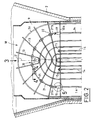
- Figure 1 is an exploded perspective view in partial section of a pressurized water nuclear reactor steam generator according to the invention.
- FIG. 2 is a sectional view of the upper part of the bundle of the steam generator shown in FIG. 1.
- FIG. 3 is a top view along 3 in FIG. 2.
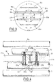
- FIG. 4 is a top view on a large scale along 4-4 of FIG. 2.
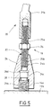
- FIG. 5 is an enlarged view in section through a vertical plane of detail 5 of FIG. 2.
- the casing 2 contains the bundle of tubes of the steam generator constituted by tubes 5 bent in a U shape and comprising at their upper part, semi-circular hangers 5b and two straight parts 5a.
- the straight parts 5a of the bundle tubes are crimped at their ends into the tube plate 3, so as to open into a water box 7 in two parts separated by a partition 8.
- the pressurized water from the nuclear reactor enters one of the parts of the water box 7 via an inlet pipe 6a, flows through the tubes of the bundle and then leaves through an outlet pipe 6b.
- the bundle of tubes 5 is surrounded by a bundle casing 9 making it possible to channel the feed water entering the casing of the steam generator by an inlet pipe 11.
- the feed water of the steam generator circulates first from top to bottom in the annular space around the envelope of bundle 9 then from bottom to top in contact with the tubes 5 of the bundle, so as to heat up then to vaporize and to emerge in the form of vapor by the upper tube 12 of the steam generator.
- the upper part of the bundle of tubes 5 is constituted by the juxtaposition of hangers of semi-circular shape whose radii are decreasing from the outside towards the inside of a flat sheet as shown in FIG. 1.
- the different successive layers of tubes of the bundle parallel to each other comprise external hangers of decreasing diameters so that the upper part of the bundle constitutes a substantially hemispherical assembly called a bun.
- the straight parts 5a of the tubes 5 are held by spacer plates 10 which prevent the tubes from vibrating when the steam generator is in operation under the effect of the circulation of exchange fluids.
- the tubular plate 3 and the spacer plates 10 are pierced in a network of through openings allowing the passage of the straight branches 5a of the tubes 5, for their fixing or their maintenance in an arrangement such that the branches 5a of the tubes are all mutually parallel and arranged in the axial direction of the beam which is the vertical direction when the steam generator 1 is in service in the nuclear reactor.
- the tubes 5 are arranged in planar plies parallel to each other, because the tubular plate 3 and the spacer plates 10 are pierced with openings aligned in straight rows successive.
- the two branches of each of the tubes are engaged in two aligned openings in the same row located on either side of the central part of the spacer plates and of the tube plate.
- the network of openings of the tube plate and of the spacer plates also constitutes rectilinear rows in a direction perpendicular to the parallel plies of tubes so that the bent tubes are also aligned in a direction perpendicular to the section plane of FIG. 1.
- bent tubes with a smaller radius of curvature located at the central part of the bundle define a free central aisle inside the bundle on either side of which the rectilinear parts of the tubes are arranged symmetrically.
- anti-vibration bars 13 each comprising two branches connected to each other at the central part 13a of the anti-vibration bar located inside the beam.
- the two branches of each of the antivibration bars can be connected to each other in an articulated manner and thus constitute a piece in the form of a compass or be produced in the form of a folded bar, the central part 13a constituting the folded part.
- the spacer plates 10 are held inside the bundle 4 in parallel arrangements and spaced from one another along the length of the straight branches 5a of the bundle tubes, by tie rods 14 arranged inside the bundle 4 in arrangements parallel to the straight branches 5a of the tubes 5.
- the tie rods 14 are fixed in the tubular plate 3 and pass through each of the spacer plates 10 inside an opening of the network of openings for crossing the tubes 5.
- the tie rods 14 are fixed to each of the spacer plates 10 which they pass through, at the level of the corresponding crossing opening, for example by mechanical devices and / or by welds.
- the straight tie rods 14 are fixed at their upper part to the upper spacer plate 10a, by means of mechanical devices such as nuts and locking washers fixed to a threaded end part of the tie rod protruding above the upper spacer plate 10a.
- the fastening by nuts of the tie rods 14 is completed by welds, so as to ensure the blocking and the captivity of the fixing parts.
- FIGS. 1 and 2 there are shown a few tubes 5 of a flat sheet 18 situated in the vicinity of the central part of the bundle of the steam generator and a set of four V-shaped anti-vibration bars 13 each comprising two rectilinear branches arranged in substantially radial directions inside the bun of the bundle 4, in contact with the tubes 5 of the flat sheet 18.
- the four anti-vibration bars 13 whose branches form variable angles between them constitute a set or set of anti-vibration bars interposed between two adjacent plies 18 of tubes 5 of the bundle.
- the anti-vibration bars 13 are engaged more or less deeply inside the bun of the bundle 4, so that the successive branches of the different anti-vibration bars make substantially constant angles between them.
- the set of anti-vibration bars has four bars and eight branches.
- the anti-vibration bars 13 of a set of bars intended to come into contact with a flat sheet 18 of tubes are placed on the sheet 18 which has just been formed.
- the anti-vibration bars 13 which are not held are liable to tilt around their internal part 13a, between the two plies of tubes 18 with which they are in contact when the steam generator is rotated about its axis 2 'on the rollers of the tacker, so as to carry out various mounting or welding operations.
- the sets of anti-vibration bars 13 interposed between certain plies of tubes 18 can be immobilized in a precise mounting position, using a metal hoop 20 having a shape analogous to the shape of the bent parts 5b of the tubes 5, c that is to say a substantially semi-circular shape.
- the arch 20 is fixed by devices 19 which will be described in more detail in the following description, on the upper spacer plate 10a of the generator. steam, in the extension of two tie rods 14 for holding the spacer plates 10.
- the sheet of tubes 18 represented in FIGS. 1 and 2 comprises tubes 5 engaged in aligned openings of the spacer plates 10 and of the tube plate 3, two of these openings being reserved for the passage and the fixing of two retaining rods 14 .
- the arch 20 is made up of successive segments 21 in the shape of a semicircle.
- the segments 21'a and 21'b situated at the ends of the arch 20 are fixed above the upper face of the upper spacer plate 10a, by means of the fixing devices 19.
- the successive segments 21 of the arch 20, between the segments 21'a and 21'b, are connected to each other end to end and to the anti-vibration bars 13, by connecting devices 22 which will be described in more detail with reference to Figure 4.
- FIG. 4 shows two successive segments 21a and 21b of the arch 20 at a connection zone 22 of the segments 21 between them and with two branches of anti-vibration bars 13 inserted between tubes 5 of adjacent layers of the steam generator harness.
- the segments 21a and 21b are cut in the shape of a semicircle and each have at their ends located opposite at the level of the connection zone 22, a connection yoke.
- the yokes 22a, 22b of each of the segments 21a and 21b are placed opposite one another and opposite an end portion of the segment on which they are to be assembled.
- the end parts of the segments 21a and 21b and the yokes 22a, 22b are crossed by openings having a threaded part.
- the yokes 22a and 22b are offset laterally with respect to the median plane of the corresponding segments 21a and 21b, so that in the assembly position of the segments 21a and 21b, there remains a space between the yoke 22a of the segment 21a and the segment 21b and between the yoke 22b of the segment 21b and the segment 21a allowing the introduction and the fixing of a branch of an anti-vibration bar 13.
- the yokes 22a and 22b and the hoop segments 21a and 21b are capable of securing two branches of anti-vibration bars 13 interposed in two spaces between the ply 18 and an adjacent ply, on one side and the other of the ply 18.
- the successive segments such as 21a and 21b of the arch 20 are joined together by screws such as 23a and 23b.
- the two branches of anti-vibration bars 13 arranged on either side of the ply of tubes 18 are clamped and held firmly between the yokes and the end parts of the segments.
- the device 19 for fixing an end segment such as 21 ′ a of the arch 20 comprises a first element 24 crossed by two successive tapped openings 24 a, 24 b having the same axis, a threaded rod 25 secured to a nut 26 and a second element constituted by the end part of the segment 21'a in which a threaded hole is machined.
- the device 19 comprising the first element 24, the second element 21'a and the rod 25 constitutes a tensioner making it possible to exert traction on one end of the arch 20 and of securing this arch on the upper spacer plate 10a.
- the first element 24 has, along its axis, a first tapped opening 24a and a second tapped opening 24b with a diameter less than the diameter of the tapped opening 24a separated by a smooth intermediate opening 24c having an intermediate diameter between the diameter of the openings 24a and 24b and by a groove 24d.
- the tie rod 14, in the extension of which one end of the ring 20 is placed, comprises a threaded end part 14a projecting above the upper spacer plate 10a.
- the threaded opening 24a of the element 24 has a diameter and a pitch allowing the fixing by screwing of the element 24 on the end portion 14a of the tie rod 14.
- a blocking and abutment piece 28 is placed inside the intermediate opening 24c on which the part 14a of the tie rod abuts when the element 24 is screwed.
- the rod 25 comprises two threaded parts 25a and 25b having reverse pitches, on either side of the nut 26.
- the end segment 21'a of the hoop 20 has a tapped opening whose diameter and pitch allow the screwing of the part 25a of the rod 25.
- the threaded opening 24b has a diameter and a pitch allowing the screwing of the part 25b of the rod 25.
- the rod 25 is screwed into the tapped opening 24b of the element 24 by its part 25b and in the tapped opening of the end segment 21'a of the arch, by its part 25a.
- the tensioning and fixing of the arch 20 are carried out by means of the nut 26 of the device 19 which constitutes a tensioner.
- the establishment of the ring 20 can therefore be carried out during the assembly of the bundle, by assembling the successive segments 21 of the ring between them and to the anti-vibration bars placed on either side of the ply of tubes being mounting; the fastening devices 19 at each end of the hoop 20 are put in place and tightened so as to ensure the tension of the hoop 20 and the fixing in place of the two sets of anti-vibration bars 13 arranged on either side of the sheet of tubes 18.
- the rod 25 can be locked relative to the part 24 by a weld 27, after tightening and tensioning of the ring.
- FIG. 3 there is shown in a top view, four arches 20a, 20b, 20c and 20d of a steam generator produced according to the invention, the arches 20a and 20b on the one hand and 20c and 20d of on the other hand being symmetrical to each other with respect to the central aisle of the steam generator whose axis 28 has been shown in FIG. 3.
- the upper spacer plate 10a of the steam generator is pierced with openings arranged in a network allowing the passage of the tubes of the bundle and the tie rods for fixing the spacer plates.
- FIG 3 there is shown only the end portions of the tie rods 14 fixed on the spacer plate 10a.
- the arches 20a, 20b, 20c and 20d are fixed by their ends to the spacer plate 10a, each in the extension of two tie rods 14.
- the tie rods 14 in the extension of which the arches are fixed are all arranged on a circle 29 concentric with respect to the spacer plate 10a.
- the arches 20a and 20b on the one hand and 20c and 20d on the other hand can be assembled and put in place, during the mounting of the steam generator tubes, by connection of modular segments in the form of semicircular arcs comprising assembly means at their end part.
- the assembled arches can be fixed on the spacer plate 10a and tensioned by fixing devices 19 connected to the end parts of the corresponding tie rods 14.
- the hoops for fixing the anti-vibration bars of the steam generator according to the invention are of course left in place in the bun after mounting the steam generator, so that these hoops also ensure the maintenance of the anti-vibration bars and the stiffening of the bun of the steam generator during operation of this generator.
- the metal hoop according to the invention holds in place the elements added in the bun of the steam generator (anti-vibration bars) and thus ensures the anti-flight function.
- the devices for fixing the arches on the upper spacer plate in the extension of the tie rods may be different from the tensioners 19 which have been described above.
- the invention applies not only to steam generators of nuclear pressurized water reactors but also to other steam generators or heat exchangers comprising a bundle of curved tubes arranged in planar layers parallel to each other.
Landscapes
- Engineering & Computer Science (AREA)
- Physics & Mathematics (AREA)
- Thermal Sciences (AREA)
- Mechanical Engineering (AREA)
- General Engineering & Computer Science (AREA)
- Heat-Exchange Devices With Radiators And Conduit Assemblies (AREA)
Claims (9)
- Wärmeaustauscher mit einem Bündel von U-förmig gebogenen Wärmeaustauschrohren (5), die jeweils zwei geradlinige Teile (5a) und einen gebogenen Teil (5b) aufweisen, einer Rohrplatte (3) und einer Anzahl von Zwischenplatten (10), die zueinander parallel und in Längsrichtung der geradlinigen Teile (5a) der Rohre (5) beabstandet sind, in denen die Rohre (5) des Bündels im Inneren durchgehender Öffnungen in Eingriff stehen, die die Halterung der Rohre (5) in zueinander ebenen Schichten (18) sicherstellen, wobei Spannstäbe (14) zur Halterung der Zwischenplatten (10) im Inneren des Bündels parallel zu den geraden Teilen der Rohre (5) angeordnet sind und Gruppen von schwingungsneutralisierenden Stangen (13) zwischen den gebogenen Teilen (5b) der Rohre (5) angeordnet sind, die in benachbarten Schichten (18) angeordnet sind, dadurch gekennzeichnet, daß er außerdem für die Halterung mindestens einer Gruppe von schwingungsneutralisierenden Stangen (13), die zwischen den Rohren (5) zweier benachbarter Schichten (18) angeordnet sind, mindestens einen Metallbogen (20) aufweist, der eine Form darbietet, die analog ist zur Form der gebogenen Teile (5b) der Rohre (5) des Bündels, der mit jedem seiner Enden an der Zwischenplatte (10a) befestigt ist, die den gebogenen Teilen (5b) der Rohre (5) nächstgelegen sind, in der Verlängerung zweier Spannstäbe (14), angeordnet zwischen zwei Rohren (5) einer Rohrschicht (18), und mit Befestigungsmitteln (22) für die Gruppe von schwingungsneutralisierenden Stangen (13), die zwischen der Schicht (18), in welcher der Bogen (20) angeordnet ist, und mindestens einer benachbarten Schicht angeordnet sind.
- Wärmeaustauscher nach Anspruch 1, dadurch gekennzeichnet, daß der Metallbogen (20) von aufeinanderfolgenden Segmenten (21) gebildet ist, die aneinander mit Montagevorrichtungen (22) angebracht sind, die auch die Befestigung der schwingungsneutralisierenden Stangen (13) sicherstellen.
- Wärmeaustauscher nach Anspruch 2, dadurch gekennzeichnet, daß der Bogen (20), der eine halbkreisartige Form darbietet, von kreisbogenförmigen, aufeinanderfolgenden Segmenten (21) gebildet ist.
- Wärmeaustauscher nach irgendeinem der Ansprüche 2 und 3, dadurch gekennzeichnet, daß die aufeinanderfolgenden Segmente (21) des Bogens (20) durch Verschraubung aneinander angebracht sind und Montageteile (22a, 22b; 21a, 21b) aufweisen, zwischen denen die schwingungsneutralisierenden Stangen (13) eingeklemmt sind.
- Wärmeaustauscher nach irgendeinem der Ansprüche 1 bis 4, dadurch gekennzeichnet, daß der Bogen (20) mit jedem seiner Enden an der Zwischenplatte (10a) unter Zwischenanordnung von Befestigungsvorrichtungen (19) befestigt ist, die als Spanneinrichtungen ausgebildet sind, um eine Zugwirkung auf die Enden des Bogens (20) auszuüben.
- Wärmeaustauscher nach Anspruch 5, dadurch gekennzeichnet, daß die Befestigungsvorrichtung (19), die in Form einer Spanneinrichtung gebildet ist, ein erstes Element (24), das Mittel (24a) zur Befestigung auf der Zwischenplatte (10a) und eine Gewindebohrung (24b) aufweist, eine Stange (25), die zwei gegenläufige Gewindeteile (25a, 25b) und eine Mutter (26) zwischen den beiden Gewindeteilen aufweist, und ein zweites Element (21'a) aufweist, das ein Endsegment des Bogens (20) bildet und eine Gewindeöffnung aufweist, wobei die Gewindestange (25) gleichzeitig mit ihren gegenläufigen Gewindeteilen (25a, 25b) in die Gewindeöffnungen (24b) des ersten Elements (24), das fest mit der Zwischenplatte (10a) verbunden ist, und des zweiten Elements (21'a) eingeschraubt werden kann, das ein Endsegment des Bogens (20) bildet.
- Wärmeaustauscher nach Anspruch 6, dadurch gekennzeichnet, daß die Mittel (24a) zur Befestigung des ersten Elements (24) auf der Zwischenplatte (10a) eine Gewindebohrung (24a) sind, die imstande ist, auf einen Gewindeteil (14a) eines Spannstabes (14) aufgeschraubt zu werden, der die Zwischenplatte (10a) durchsetzt.
- Wärmeaustauscher nach irgendeinem der Ansprüche 1 bis 7, dadurch gekennzeichnet, daß er mindestens zwei Bögen (20a, 20b, 20c, 20d) aufweist, die in bezug auf eine Symmetrieebene (28) des Bündels des Dampferzeugers symmetrisch angeordnet sind.
- Benutzung eines Wärmeaustauschers nach irgendeinem der Ansprüche 1 bis 8 als Dampferzeuger eines Druckwasser-Kernreaktors.
Applications Claiming Priority (2)
| Application Number | Priority Date | Filing Date | Title |
|---|---|---|---|
| FR9310158 | 1993-08-20 | ||
| FR9310158A FR2709174B1 (fr) | 1993-08-20 | 1993-08-20 | Echangeur de chaleur comportant des moyens de maintien de barres antivibratoires intercalés entre les tubes du faisceau de l'échangeur. |
Publications (2)
| Publication Number | Publication Date |
|---|---|
| EP0639741A1 EP0639741A1 (de) | 1995-02-22 |
| EP0639741B1 true EP0639741B1 (de) | 1996-12-11 |
Family
ID=9450337
Family Applications (1)
| Application Number | Title | Priority Date | Filing Date |
|---|---|---|---|
| EP94401848A Expired - Lifetime EP0639741B1 (de) | 1993-08-20 | 1994-08-11 | Wärmetauscher mit Haltevorrichtung für zwischen die Rohre eingelegte Dämpfungsstangen |
Country Status (8)
| Country | Link |
|---|---|
| US (1) | US5447191A (de) |
| EP (1) | EP0639741B1 (de) |
| JP (1) | JPH07151487A (de) |
| KR (1) | KR950006417A (de) |
| CN (1) | CN1102500A (de) |
| CA (1) | CA2130491A1 (de) |
| DE (1) | DE69401103D1 (de) |
| FR (1) | FR2709174B1 (de) |
Families Citing this family (30)
| Publication number | Priority date | Publication date | Assignee | Title |
|---|---|---|---|---|
| FR2731508B1 (fr) * | 1995-03-09 | 1997-05-09 | Framatome Sa | Echangeur de chaleur, a tubes en u, equipe d'un dispositif de calage des tubes, antivibratoire et anti-envol |
| US5699395A (en) * | 1995-10-05 | 1997-12-16 | Westinghouse Electric Corporation | Segmented stayrod for restricting transverse displacement of a nuclear heat exchanger tube support plate |
| JP2007271157A (ja) * | 2006-03-31 | 2007-10-18 | Mitsubishi Heavy Ind Ltd | 伝熱管の支持構造 |
| EP2188582A1 (de) * | 2007-09-11 | 2010-05-26 | Behr GmbH & Co. KG | Wärmetauscher, insbesondere für ein kraftfahrzeug |
| JP5086821B2 (ja) * | 2008-01-18 | 2012-11-28 | 三菱重工業株式会社 | 蒸気発生器の製造方法および固定治具 |
| US8572847B2 (en) * | 2008-07-25 | 2013-11-05 | Babcock & Wilcox Canada Ltd. | Tube support system for nuclear steam generators |
| AU2010346932B8 (en) * | 2010-02-26 | 2013-10-17 | Daikin Europe N.V. | Coil support member |
| DE102010040278A1 (de) * | 2010-09-06 | 2012-03-08 | Siemens Aktiengesellschaft | Wärmetauscher |
| DE102010040281A1 (de) * | 2010-09-06 | 2012-03-08 | Siemens Aktiengesellschaft | Wärmetauscher |
| US9697919B2 (en) * | 2010-12-29 | 2017-07-04 | Westinghouse Electric Company, Llc | Anti-vibration tube support plate arrangement for steam generators |
| CN102161143A (zh) * | 2011-04-01 | 2011-08-24 | 上海电气核电设备有限公司 | 一种用于蒸汽发生器管束的抗震条装配辅助工装 |
| US9534779B2 (en) * | 2011-04-04 | 2017-01-03 | Westinghouse Electric Company Llc | Steam generator tube lane flow buffer |
| JP5868649B2 (ja) * | 2011-10-06 | 2016-02-24 | 三菱重工業株式会社 | 振止部材取付構造および蒸気発生器 |
| US20140014294A1 (en) * | 2012-07-13 | 2014-01-16 | Areva Np Inc. | U-Bend Tube Compression/Distortion Stabilization System (CDSS) |
| CN103659169B (zh) * | 2012-09-23 | 2016-06-22 | 丹阳市龙鑫合金有限公司 | 一种制备核电机组的抗振条组件的方法 |
| US20140116360A1 (en) * | 2012-10-31 | 2014-05-01 | Westinghouse Electric Company Llc | Method and apparatus for securing tubes in a steam generator against vibration |
| CN103871488A (zh) * | 2012-12-13 | 2014-06-18 | 中国核动力研究设计院 | 一种用于压水堆核电厂蒸汽发生器的防振条结构 |
| CN103317245B (zh) * | 2013-06-05 | 2015-08-19 | 上海电气核电设备有限公司 | 一种核电蒸汽发生器穿管和抗震条装焊的方法 |
| CN103594127A (zh) * | 2013-11-13 | 2014-02-19 | 南通曙光新能源装备有限公司 | 一种节能核电蒸发器 |
| JP6499478B2 (ja) * | 2015-03-05 | 2019-04-10 | 三菱重工業株式会社 | 蒸気発生器及び原子力プラント、並びに蒸気発生器の耐震補強方法 |
| CN106855226B (zh) * | 2015-12-09 | 2019-03-19 | 中广核工程有限公司 | 核电厂蒸汽发生器防振条结构 |
| CN106197125A (zh) * | 2016-08-17 | 2016-12-07 | 哈尔滨汽轮机厂辅机工程有限公司 | 一种光热发电再热器用的u形换热管支撑结构 |
| CN106500939B (zh) * | 2016-10-31 | 2018-09-11 | 中国核动力研究设计院 | 一种传热管u型段等效刚度支撑结构及实现支撑的方法 |
| CN106765024B (zh) * | 2016-11-24 | 2019-09-13 | 中广核工程有限公司 | 核电厂蒸汽发生器防振条结构 |
| CN107221357B (zh) * | 2017-05-24 | 2019-04-09 | 安徽科创智慧知识产权服务有限公司 | 整体减振式反应堆蒸发器中的换热腔 |
| CN107671459A (zh) * | 2017-10-10 | 2018-02-09 | 汉能机器人自动化(丹阳)有限公司 | 单工位汽车防撞梁焊接系统 |
| CN108954288B (zh) * | 2018-07-11 | 2020-01-07 | 东方电气(广州)重型机器有限公司 | 一种管束抗震条阻尼装置及限位方法 |
| CN109579599B (zh) * | 2018-12-27 | 2024-04-16 | 苏州海陆重工股份有限公司 | 釜式蒸发器中u形换热管束的防振机构 |
| EP3957942A1 (de) * | 2020-08-21 | 2022-02-23 | Lummus Novolen Technology Gmbh | System und verfahren eines vertikalen wärmetauschers mit stabumlenkblech |
| CN113866269B (zh) * | 2021-09-16 | 2024-07-09 | 中国科学院南海海洋研究所 | 一种垂向横截面分层声学测量系统及方法 |
Family Cites Families (6)
| Publication number | Priority date | Publication date | Assignee | Title |
|---|---|---|---|---|
| US2853278A (en) * | 1956-04-05 | 1958-09-23 | Griscom Russell Co | Anti-vibration crate for heat exchange tubes |
| US3575236A (en) * | 1969-08-13 | 1971-04-20 | Combustion Eng | Formed plate tube spacer structure |
| FR2603364B1 (fr) * | 1986-08-27 | 1988-11-10 | Framatome Sa | Procede de placement de tubes dans un generateur de vapeur |
| US5005637A (en) * | 1986-11-05 | 1991-04-09 | Phillips Petroleum Company | Heat exchanger U-bend tube support |
| FR2644281B1 (fr) * | 1989-03-09 | 1991-06-07 | Framatome Sa | Dispositif de stabilisation des tubes du faisceau d'un generateur de vapeur comportant des barres antivibratoires |
| FR2664965B1 (fr) * | 1990-07-20 | 1992-11-06 | Framatome Sa | Dispositif de calage antivibratoire de tubes d'un echangeur de chaleur. |
-
1993
- 1993-08-20 FR FR9310158A patent/FR2709174B1/fr not_active Expired - Fee Related
-
1994
- 1994-08-11 DE DE69401103T patent/DE69401103D1/de not_active Expired - Lifetime
- 1994-08-11 EP EP94401848A patent/EP0639741B1/de not_active Expired - Lifetime
- 1994-08-19 KR KR1019940020465A patent/KR950006417A/ko not_active Ceased
- 1994-08-19 CN CN94109103A patent/CN1102500A/zh active Pending
- 1994-08-19 US US08/292,824 patent/US5447191A/en not_active Expired - Fee Related
- 1994-08-19 CA CA002130491A patent/CA2130491A1/fr not_active Abandoned
- 1994-08-22 JP JP6197037A patent/JPH07151487A/ja active Pending
Also Published As
| Publication number | Publication date |
|---|---|
| DE69401103D1 (de) | 1997-01-23 |
| JPH07151487A (ja) | 1995-06-16 |
| CN1102500A (zh) | 1995-05-10 |
| EP0639741A1 (de) | 1995-02-22 |
| FR2709174A1 (fr) | 1995-02-24 |
| FR2709174B1 (fr) | 1995-11-17 |
| CA2130491A1 (fr) | 1995-02-21 |
| US5447191A (en) | 1995-09-05 |
| KR950006417A (ko) | 1995-03-21 |
Similar Documents
| Publication | Publication Date | Title |
|---|---|---|
| EP0639741B1 (de) | Wärmetauscher mit Haltevorrichtung für zwischen die Rohre eingelegte Dämpfungsstangen | |
| EP0387131B1 (de) | Vorrichtung zur Stabilisierung von Rohren eines Dampferzeugerrohrbündels mit schwingungsneutralisierenden Stangen | |
| EP0905384B1 (de) | Vorrichtung zum Zusammenbau zweier Rohre | |
| EP0731328B1 (de) | Wärmetauscher mit U-Röhren, mit einer Anti-Auftrieb- und schwingungsneutralisierender Rohrhalterungsvorrichtung | |
| EP0633427A1 (de) | Wärmetauscher mit U-Rohrbündel und schwingungsneutralisierenden Stangen zwischen dem gekrümmten Teil | |
| EP0654636B1 (de) | Vorrichtung für schwingungsneutralisierendes Festsetzen von Wärmetauscherrohren und seine Verwendung | |
| EP0300845B1 (de) | Vorrichtung für schwingungsneutralisierendes Festsetzen von Teilen einer Einrichtung und insbesondere schwingungsneutralisierende Stangen für Rotoren eines Dampferzeugers | |
| EP0467755B1 (de) | Vorrichtung für schwingungsneutralisierendes Festsetzen von Wärmetauscherrohren | |
| EP0078728B1 (de) | Schwingungsdämpfende Halterung für ein Rohrbündel, insbesondere für einen Dampferzeuger, und Verfahren zum Montieren dieser Halterung | |
| EP0544579B1 (de) | Wärmetauscher mit U-Rohren und Anti-Auftriebshalterung | |
| EP0173586B1 (de) | Wärmetauscher mit Rohrbündel, von einer zylindrischen Hülle umgeben, welche radial in einer äusseren Hülle festgehalten wird | |
| CA2165724C (fr) | Accouplement flexible pour arbres tournants | |
| FR2531258A1 (fr) | Element combustible nucleaire et procede de realisation | |
| BE857796A (fr) | Dispositif mecanique dissipateur d'energie | |
| EP1475344B1 (de) | Führungsvorrichtung für Hydraulikschläuche | |
| FR2714626A1 (fr) | Dispositif de maintien d'un faisceau de tubes d'un échangeur de chaleur pendant la fabrication et le transport de l'échangeur de chaleur. | |
| EP2534741B1 (de) | Gitterkanal für kabel | |
| FR2614094A1 (fr) | Grille entretoise de maintien transversal des tubes du faisceau d'un echangeur de chaleur et procede de montage et utilisation d'une telle grille entretoise | |
| FR2748795A1 (fr) | Dispositif de maintien d'une partie d'extremite d'un faisceau de tubes d'un echangeur de chaleur | |
| FR2518730A1 (fr) | Perfectionnements a la construction de raffineurs ou echangeurs tubulaires | |
| FR2755288A1 (fr) | Embout superieur d'un assemblage de combustible | |
| FR2665506A1 (fr) | Dispositif de suspension d'une canalisation a un element fixe d'une construction. | |
| FR2620177A1 (fr) | Dispositif de renforcement d'un pylone | |
| FR3024950A1 (fr) | Module de mise en contact de liquide et de gaz et ensemble de mise en contact comprenant une succession de tels modules de mise en contact | |
| FR2731329A1 (fr) | Canape lit baignoire |
Legal Events
| Date | Code | Title | Description |
|---|---|---|---|
| PUAI | Public reference made under article 153(3) epc to a published international application that has entered the european phase |
Free format text: ORIGINAL CODE: 0009012 |
|
| AK | Designated contracting states |
Kind code of ref document: A1 Designated state(s): BE DE ES GB SE |
|
| 17P | Request for examination filed |
Effective date: 19950102 |
|
| GRAG | Despatch of communication of intention to grant |
Free format text: ORIGINAL CODE: EPIDOS AGRA |
|
| GRAH | Despatch of communication of intention to grant a patent |
Free format text: ORIGINAL CODE: EPIDOS IGRA |
|
| 17Q | First examination report despatched |
Effective date: 19960507 |
|
| GRAH | Despatch of communication of intention to grant a patent |
Free format text: ORIGINAL CODE: EPIDOS IGRA |
|
| GRAA | (expected) grant |
Free format text: ORIGINAL CODE: 0009210 |
|
| AK | Designated contracting states |
Kind code of ref document: B1 Designated state(s): BE DE ES GB SE |
|
| PG25 | Lapsed in a contracting state [announced via postgrant information from national office to epo] |
Ref country code: GB Effective date: 19961211 Ref country code: ES Free format text: THE PATENT HAS BEEN ANNULLED BY A DECISION OF A NATIONAL AUTHORITY Effective date: 19961211 |
|
| REF | Corresponds to: |
Ref document number: 69401103 Country of ref document: DE Date of ref document: 19970123 |
|
| PG25 | Lapsed in a contracting state [announced via postgrant information from national office to epo] |
Ref country code: SE Effective date: 19970311 |
|
| PG25 | Lapsed in a contracting state [announced via postgrant information from national office to epo] |
Ref country code: DE Effective date: 19970312 |
|
| GBV | Gb: ep patent (uk) treated as always having been void in accordance with gb section 77(7)/1977 [no translation filed] |
Effective date: 19961211 |
|
| PLBE | No opposition filed within time limit |
Free format text: ORIGINAL CODE: 0009261 |
|
| STAA | Information on the status of an ep patent application or granted ep patent |
Free format text: STATUS: NO OPPOSITION FILED WITHIN TIME LIMIT |
|
| 26N | No opposition filed | ||
| PGFP | Annual fee paid to national office [announced via postgrant information from national office to epo] |
Ref country code: BE Payment date: 19990809 Year of fee payment: 6 |
|
| PG25 | Lapsed in a contracting state [announced via postgrant information from national office to epo] |
Ref country code: BE Free format text: LAPSE BECAUSE OF NON-PAYMENT OF DUE FEES Effective date: 20000831 |
|
| BERE | Be: lapsed |
Owner name: FRAMATOME Effective date: 20000831 |