EP0905342A2 - Scharnier und Vorrichtung mit Scharnier - Google Patents
Scharnier und Vorrichtung mit Scharnier Download PDFInfo
- Publication number
- EP0905342A2 EP0905342A2 EP98307674A EP98307674A EP0905342A2 EP 0905342 A2 EP0905342 A2 EP 0905342A2 EP 98307674 A EP98307674 A EP 98307674A EP 98307674 A EP98307674 A EP 98307674A EP 0905342 A2 EP0905342 A2 EP 0905342A2
- Authority
- EP
- European Patent Office
- Prior art keywords
- heat conducting
- heat
- conducting portion
- movable member
- electronic apparatus
- Prior art date
- Legal status (The legal status is an assumption and is not a legal conclusion. Google has not performed a legal analysis and makes no representation as to the accuracy of the status listed.)
- Granted
Links
Images


Classifications
-
- H—ELECTRICITY
- H05—ELECTRIC TECHNIQUES NOT OTHERWISE PROVIDED FOR
- H05K—PRINTED CIRCUITS; CASINGS OR CONSTRUCTIONAL DETAILS OF ELECTRIC APPARATUS; MANUFACTURE OF ASSEMBLAGES OF ELECTRICAL COMPONENTS
- H05K7/00—Constructional details common to different types of electric apparatus
- H05K7/14—Mounting supporting structure in casing or on frame or rack
- H05K7/16—Mounting supporting structure in casing or on frame or rack on hinges or pivots
-
- G—PHYSICS
- G06—COMPUTING OR CALCULATING; COUNTING
- G06F—ELECTRIC DIGITAL DATA PROCESSING
- G06F1/00—Details not covered by groups G06F3/00 - G06F13/00 and G06F21/00
- G06F1/16—Constructional details or arrangements
- G06F1/1613—Constructional details or arrangements for portable computers
- G06F1/1615—Constructional details or arrangements for portable computers with several enclosures having relative motions, each enclosure supporting at least one I/O or computing function
- G06F1/1616—Constructional details or arrangements for portable computers with several enclosures having relative motions, each enclosure supporting at least one I/O or computing function with folding flat displays, e.g. laptop computers or notebooks having a clamshell configuration, with body parts pivoting to an open position around an axis parallel to the plane they define in closed position
-
- G—PHYSICS
- G06—COMPUTING OR CALCULATING; COUNTING
- G06F—ELECTRIC DIGITAL DATA PROCESSING
- G06F1/00—Details not covered by groups G06F3/00 - G06F13/00 and G06F21/00
- G06F1/16—Constructional details or arrangements
- G06F1/1613—Constructional details or arrangements for portable computers
- G06F1/1633—Constructional details or arrangements of portable computers not specific to the type of enclosures covered by groups G06F1/1615 - G06F1/1626
- G06F1/1675—Miscellaneous details related to the relative movement between the different enclosures or enclosure parts
- G06F1/1681—Details related solely to hinges
-
- E—FIXED CONSTRUCTIONS
- E05—LOCKS; KEYS; WINDOW OR DOOR FITTINGS; SAFES
- E05D—HINGES OR SUSPENSION DEVICES FOR DOORS, WINDOWS OR WINGS
- E05D11/00—Additional features or accessories of hinges
- E05D11/0081—Additional features or accessories of hinges for transmitting energy, e.g. electrical cable routing
-
- E—FIXED CONSTRUCTIONS
- E05—LOCKS; KEYS; WINDOW OR DOOR FITTINGS; SAFES
- E05D—HINGES OR SUSPENSION DEVICES FOR DOORS, WINDOWS OR WINGS
- E05D11/00—Additional features or accessories of hinges
- E05D11/08—Friction devices between relatively-movable hinge parts
-
- E—FIXED CONSTRUCTIONS
- E05—LOCKS; KEYS; WINDOW OR DOOR FITTINGS; SAFES
- E05F—DEVICES FOR MOVING WINGS INTO OPEN OR CLOSED POSITION; CHECKS FOR WINGS; WING FITTINGS NOT OTHERWISE PROVIDED FOR, CONCERNED WITH THE FUNCTIONING OF THE WING
- E05F1/00—Closers or openers for wings, not otherwise provided for in this subclass
- E05F1/08—Closers or openers for wings, not otherwise provided for in this subclass spring-actuated, e.g. for horizontally sliding wings
- E05F1/10—Closers or openers for wings, not otherwise provided for in this subclass spring-actuated, e.g. for horizontally sliding wings for swinging wings, e.g. counterbalance
- E05F1/12—Mechanisms in the shape of hinges or pivots, operated by springs
- E05F1/123—Mechanisms in the shape of hinges or pivots, operated by springs with a torsion bar
-
- E—FIXED CONSTRUCTIONS
- E05—LOCKS; KEYS; WINDOW OR DOOR FITTINGS; SAFES
- E05Y—INDEXING SCHEME ASSOCIATED WITH SUBCLASSES E05D AND E05F, RELATING TO CONSTRUCTION ELEMENTS, ELECTRIC CONTROL, POWER SUPPLY, POWER SIGNAL OR TRANSMISSION, USER INTERFACES, MOUNTING OR COUPLING, DETAILS, ACCESSORIES, AUXILIARY OPERATIONS NOT OTHERWISE PROVIDED FOR, APPLICATION THEREOF
- E05Y2999/00—Subject-matter not otherwise provided for in this subclass
Definitions
- the present invention relates to a hinge for an electronic apparatus such as a portable electronic apparatus and to an electronic apparatus equipped with a hinge.
- a portable computer for example, is equipped with a main body and a display portion thereof. This display portion can be opened and closed with respect to the main body through the intermediation of a hinge.
- a typical portable computer of this type is a computer called a notebook personal computer.
- a stationary member and a movable member of the hinge are mechanically joined together such that the movable member can rotate with respect to the stationary member by a fixed torque.
- a material satisfying the requisite mechanical strength is adopted for the stationary member, the movable member, etc.
- heat conduction for heat dissipation is not taken into consideration.
- a large heat sink is separately provided for natural heat dissipation, or air cooling is forcibly effected by using a fan or the like.
- An embodiment of the present invention seeks to solve the above problems and to provide a hinge for electronic apparatus and an electronic apparatus equipped with a hinge in which there is no need to increase the size of the electronic apparatus and in which heat dissipation can be effected.
- a hinge for foldably joining first and second portions of an electronic apparatus to each other, the hinge comprising: a stationary member which includes strength maintaining portion for maintaining mechanical strength and a heat conducting portion for effecting heat conduction and which is provided on the first portion, a movable member which includes strength maintaining portion for maintaining mechanical strength and a heat conducting portion for effecting heat conduction and which is provided on the second portion, and a joint portion for joining the stationary member and the movable member to each other while effecting heat conduction between the heat conducting portion of the stationary member and the heat conducting portion of the movable member.
- the stationary portion has a strength maintaining portion for maintaining mechanical strength and a heat conducting portion for effecting heat conduction.
- the joint portion joins the stationary member and the movable member to each other while effecting heat conduction between the heat conducting portion of the stationary member and the heat conducting portion of the movable member.
- an electronic apparatus having a hinge which includes first and second portions, the second portion being foldable with respect to the first portion
- the electronic apparatus comprising: a stationary member which includes strength maintaining portion for maintaining mechanical strength and a heat conducting portion for effecting heat conduction and which is provided on the first portion, a movable member which includes strength maintaining portion for maintaining mechanical strength and a heat conducting portion for effecting heat conduction and which is provided on the second portion, and a joint portion for joining the stationary member and the movable member to each other while effecting heat conduction between the heat conducting portion of the stationary member and the heat conducting portion of the movable member.
- the stationary member has a strength maintaining portion for maintaining mechanical strength and a heat conducting portion for effecting heat conduction.
- the movable member has a strength maintaining portion for maintaining mechanical strength and a heat conducting portion for effecting heat conduction.
- the joint portion joins the stationary member and the movable member to each other while effecting heat conduction between the heat conducting portion of the stationary member and the heat conducting portion of the movable member.
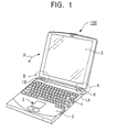
- Fig. 1 shows an example of an electronic apparatus equipped with an illustrative hinge according to the present invention.
- the electronic apparatus shown in Fig. 1 is a portable computer 100.
- the portable computer 100 includes a main body 2, a display portion 3, a keyboard 4, hinges 1A and 1B encircled by regions A and B, respectively, etc.
- the main body 2 includes a pointing device 5, etc.
- the display portion 3 may consist, for example, of a liquid crystal display device (LCD).
- LCD liquid crystal display device
- the display portion 3 is mounted to the main body 2 such that it can be opened and closed (folded) with respect thereto in the directions indicated by arrows R by means of the hinges 1A and 1B.
- the main body 2 it is also possible to provide the main body 2 with a device for connecting a mouse or the like, which is an external pointing means.
- the hinges 1A and 1B shown in Fig. 1 mechanically connect the display portion 3 to the rear end portion 6 of the main body 6 and, at the same time, have a function by which they effect thermal conduction and heat dissipation.
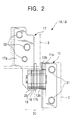
- the hinges 1A and 1B which are symmetrically arranged, have substantially the same construction. In view of this, the construction and features of only the hinge 1A will be described with reference to Figs. 2 through 6.
- the hinge 1A has a stationary member 11, a movable member 17 and a joint portion 30.
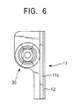
- the joint portion 30, shown in Figs. 4 through 6, is a portion that is capable of joining the stationary member 11 and the movable member 17 mechanically and in such a manner that heat conduction can be effected.
- the stationary member 11 is composed of a strength maintaining portion 11a for maintaining mechanical strength and a heat conducting portion 12 for effecting heat conduction. It is desirable that a material having a high level of mechanical strength, for example, stainless steel (SUS), which is an iron type material, be adopted for the strength maintaining portion 11a so that the requisite strength at the time of opening and closing the display portion 3 shown in Fig. 1 and the opening/driving operation itself may be maintained.
- the strength maintaining portion lla is preferably formed of a mechanically strong plate material and is, as shown in Figs. 2 and 3, formed into a substantially L-shaped configuration in sectional view.
- the heat conducting portion 12 be formed of a material suitable for heat conduction, for example, a copper type or aluminum type material.
- the heat conducting portion 12 is formed as a plate, and has a substantially L-shaped configuration so that it can be brought into close contact with the strength maintaining portion 11 and glued or fastened thereto.
- Fig. 3 shows the L-shaped sectional configuration.
- the strength maintaining portion 11a and the heat conducting portion 12 of the stationary member 11 are in close contact with each other.
- the stationary member 11 is fastened to the mounting surface side of the main body 2 (the side in contact with the main body) by, for example, screws 31.
- Fig. 4 is a perspective view showing an example of the configuration of the strength maintaining portion lla and the heat conducting portion 12 of the stationary member 11. Rectangular holes 11c and 12c are formed in the erect portion 11b of the strength maintaining portion lla and the erect portion 12b of the heat conducting portion 12, respectively.
- this movable member 17 has a strength maintaining portion 17a and a heat conducting portion 13.
- the strength maintaining portion is a portion for maintaining mechanical strength
- the heat conducting portion 13 is a portion for effecting heat conduction.
- the strength holding portion 17a it is desirable for the strength holding portion 17a to be formed of a material having a high level of mechanical strength, such as a stainless steel (SUS), which is an iron type material.
- the heat conducting portion 13 may be formed of a material providing good heat conductivity, such as a copper type or aluminum type material.
- the strength maintaining portion 17a has a substantially L-shaped configuration, and the heat conducting portion also has a substantially L-shaped configuration. However, a portion 13a of the heat conducting portion 13 is in close contact with the strength maintaining portion 17a, and an erect portion 13b of the heat conducting portion 13 is spaced apart from an erect portion 17b of the strength maintaining portion 17a.
- Fig. 4 shows three-dimensionally the strength maintaining portion 17a and the heat conducting portion 13 of the movable member 17.
- Round holes 17c and 13c are formed in the erect portion 17b of the strength maintaining portion 17a and the erect portion 13b of the heat conducting portion 13, respectively.
- the diameter of the hole 17c is smaller than the diameter of the hole 13c.
- This joint section 30 effects heat conduction between the heat conducting portion 12 of the stationary member 11 and the heat conducting portion 13 of the movable member 17 and, at the same time, joins the stationary member 11 and the movable member 17 mechanically to each other.
- Fig. 4 shows the components of this joint portion 30; it comprises a spring washer 14, a shaft 15, washers 16 and 18, a spring washer 19 and a stopper 20.
- the shaft 15 is formed of iron or the like in order to maintain the requisite mechanical strength.
- the shaft 15 includes a main body 15c, a protrusion 15a and another protrusion 15b on the other side.
- the protrusion 15a is passed through a hole 14a of the spring washer 14 and, further, through the hole 13c of the heat conducting portion 13, the hole 12c of the heat conducting portion 12, and the hole 11c of the strength maintaining portion 11.
- This protrusion 15a has end surfaces 15e formed such that the protrusion is firmly fitted into the hole 12c of the heat conducting portion 12 and the hole 11c of the strength maintaining portion 11a in such a way that it does not move therein.
- the protrusion 15a of the shaft 15 is fitted into the hole 12c of the heat conducting portion 12a and the hole 11c of the strength maintaining portion 11a, whereby it can be firmly secured in position so as not to be detached.
- the spring washer 14 is a spring member for pressing the heat conducting portion 12 of the stationary member 11 and the heat conducting portion 13 of the movable member 17 in such a way that they are in close contact with each other. It is made of a metal such as iron.
- the washer 16 is a washer arranged between the shaft 15 and the strength maintaining portion 17a of the movable member 17.
- the hole 16c of the washer 16 is a rectangular hole into which the protrusion 15b of the shaft 15 can be fitted.
- the protrusion 15b of the shaft 15 also has flat end surfaces 15f.
- the protrusion 15b is passed through the hole 17c of the strength maintaining portion 17a.
- This protrusion 15b is passed through the hole 18c of the washer 18 and the hole 19c of the spring washer 19 and firmly fitted into the hole 20c of the stopper 20. That is, the protrusion 15b of the shaft 15 can be firmly secured in position in the hole 20c of the stopper 20 so as not to be detached.
- the stationary member 11 and the movable member 17 can be integrally connected together by means of the engaging connection between the protrusion 15a of the shaft 15 and the hole 11c of the strength maintaining portion 11 and the engaging connection between the protrusion 15b of the shaft 15 and the hole 20c of the stopper 20.
- the movable member 17 can rotate with respect to the stationary member 11 in the directions of the arrows R in Fig. 3.
- the shaft 15, the washers 16 and 18, the spring washers 14 and 19, the stopper 20, etc. may be formed of a mechanically strong material, such as an iron type material.
- the heat conducting portion 12 of the stationary member 11 is positioned on the mounting surface side of the main body 2 of the computer shown in Fig. 1 (the side in contact with the main body), and can be secured in position by screws 32 as shown in Figs. 2 and 3.
- the heat conducting portion 13a of the movable member 17 is positioned on the mounting surface side of the display portion 3 of the computer 100 shown in Fig. 1 (the surface mounted to the display portion) and can be secured in position by screws 32.
- the erect portion 12b of the heat conducting portion 12 of the stationary member 11 is in close contact with the erect portion 13b of the heat conducting portion 13 of the movable member 17 and, at the same time, the spring washer 14 keeps these erect portions 12b and 13b by its resilient pressing force, so that it is possible to make the thermal resistance in these erect portions 12b and 13b of the heat conducting portions 12 and 13 as low as possible.
- the hinge 1A or 1B thus formed not only maintains mechanical strength but also effects heat conduction and heat dissipation.
- the main body 2 and the display portion 3 of the computer 100 it is possible to improve the heat conduction, making it possible for heat to be easily conducted from the side where the quantity of heat is larger, for example, the main body 2 to the side where the quantity of heat is smaller, for example, the display portion 3.
- the conduction of heat from the main body portion 2, which generates a relatively large quantity of heat, to the display portion 3, which generates a relatively small quantity of heat, is improved, whereby the requisite space for dissipation can be secured.
- the casing of the main body 2 and the display portion 3 is formed of a light metal such as magnesium
- the casing can be used as a heat sink.
- a material having good thermal conductivity offers low electrical resistance.
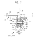
- hinges 201A and 201B shown in Fig. 7 are used instead of the hinges 1A and 1B shown in Fig. 1. These hinges 201A and 201B can be used as the hinges of the computer 100 as shown in Fig. 1.
- the hinge 201A (201B) is equipped with a stationary member 111, a movable member 117 and a joint portion 130.
- the stationary member 111 is secured to the main body 2, and the movable member 117 is secured to the display portion 3.
- the joint portion 130 effects heat conduction between the stationary member 111 and the movable member 117 while maintaining the mechanical strength of the stationary member 111 and the movable member 117.
- the stationary member 111 has a strength maintaining portion llla and a heat conducting portion 112.
- the strength maintaining portion 111a may be formed, for example, a mechanically strong material, for example, stainless steel, which is an iron type material.
- the heat conducting portion 112 is formed of a material having good heat conductivity, for example, a copper type or aluminum type material.
- the strength maintaining portion 111a and the heat conducting portion 112 have a substantially L-shaped sectional configuration, and the heat conducting portion 112 is in close contact with the strength maintaining portion 111a.
- An erect portion 111b of the strength maintaining portion 111a has a hole 111c, and an erect portion 112b of the heat conducting portion 112 has a hole 112c.
- the movable member 117 also has a strength maintaining portion 117a and a heat conducting portion 113.
- the strength maintaining portion 117a has a substantially L-shaped sectional configuration and may be formed of a mechanically strong material, such as stainless steel, which is an iron type material.
- the heat conducting portion 113 also has a substantially L-shaped sectional configuration and is formed of a material having good heat conductivity, such as a copper type or aluminum type material.
- the strength maintaining portion 117a and the heat conducting portion 113 are in close contact with each other.
- a hole 117c is formed in an erect portion 117b of the strength maintaining portion 117, and a hole 113c is formed in an erect portion 113b of the heat conducting portion 113.
- the joint portion 130 includes a shaft 160, a heat conducting ring 170 and a torque bush 180.
- One end 161 of the shaft 160 is formed as a stopper, which has a diameter larger than the diameter of the hole 117c of the strength maintaining portion 117a, thus serving as a retainer.
- An E-ring 163 is fitted onto the other end 162 of the shaft 160, and a washer 164 is arranged between this E-ring 163 and the erect portion 111b, whereby the shaft 160 is prevented from being detached from the strength maintaining portion 117a and prevented from being detached from the strength maintaining portion 111a.
- the torque bush 180 and the heat conducting ring 170 are arranged between the heat conducting portions 112 and 113. That is, the torque bush 180 and the heat conducting ring 170 are coaxially arranged around the shaft 160.
- the heat conducting ring 170 is a ring (separate member) for effecting heat conduction between the heat conducting portion 117 and the heat conducting portion 113. It is a ring formed, for example, of a material having good heat conductivity, for example, a copper type or aluminum type material.
- the torque bush is formed of resin or the like. It is a member for assisting in the rotation between the stationary member 111 and the movable member 117.
- the heat conducting portion 112 of the stationary member 111 is positioned on the mounting surface side of the main body 2 (the side in contact with the main body) and secured in position by, for example, screws.
- the heat conducting portion 113 of the movable member 117 is positioned on the mounting surface side of the display portion (the surface in contact with the mounting surface of the display portion 2), and the movable member 117 is secured to the display portion 3 side by screws or the like.
- the heat conducting portion 12 of the stationary member 11 and the heat conducting portion 13 of the movable member 17 are in direct contact with each other to thereby effect heat conduction therebetween.
- the heat conduction between the heat conducting portion 112 of the stationary member 111 and the heat conducting portion 113 of the movable member 117 is effected by using a separate heat conducting ring 170. That is, in the hinges 201A and 201B, one heat conducting portion 112 is arranged in the vicinity of the other heat conducting portion 113 but they are not in direct contact with each other.
- the hinges may be positioned on the mounting surface side of the main body 2 or the display portion 3 as shown in Figs. 3 and 7, they may also be arranged on the screwing side.
- the shaft 15 may be formed as a cylinder and a material having good heat conductivity may be passed through it.
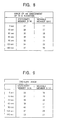
- a heat conducting portion made of aluminum was secured to each of the stationary member and the movable member of a hinge.
- the heat conducting portion on the stationary member side was heated, and the changes with time in the temperatures of the stationary member and the movable member were measured.
- the difference in temperature between the stationary member and the movable member is small in the hinge of the embodiment of the present invention shown in Fig. 8.
- the temperature on the stationary member side does not rise because heat is conducted through the hinge to the movable member side.
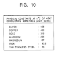
- Fig. 10 shows an example of the physical constants of heat conducting materials at 0°C used in the heat conducting portions of the embodiments of the present invention.
- the electronic apparatus to which a hinge according to the present invention is applied is a so-called portable computer.
- the electronic apparatuses to which the present invention is applicable include various types of electronic apparatus generating heat, such as a portable information terminal, a portable telephone, and a radio telegraph.
- the heat conducting portion of the stationary member and the heat conducting portion of the movable member may be positioned on the side in contact with the surface contributing heat dissipation or the heat dissipation surface or on either side thereof.
- the surface contributing to heat dissipation means the heat dissipating portion, for example, of the circuit board of the main body 2 or the display portion 3, and the heat dissipation surface means, for example, the casing of the main body 2 or the display portion 3 which is made of a light metal such as magnesium.
Landscapes
- Engineering & Computer Science (AREA)
- Theoretical Computer Science (AREA)
- Computer Hardware Design (AREA)
- Physics & Mathematics (AREA)
- Human Computer Interaction (AREA)
- General Engineering & Computer Science (AREA)
- General Physics & Mathematics (AREA)
- Mathematical Physics (AREA)
- Microelectronics & Electronic Packaging (AREA)
- Cooling Or The Like Of Electrical Apparatus (AREA)
- Casings For Electric Apparatus (AREA)
- Hinges (AREA)
- Hinge Accessories (AREA)
Applications Claiming Priority (3)
| Application Number | Priority Date | Filing Date | Title |
|---|---|---|---|
| JP26004597A JP3937523B2 (ja) | 1997-09-25 | 1997-09-25 | 電子機器用のヒンジ及びヒンジを備える電子機器 |
| JP260045/97 | 1997-09-25 | ||
| JP26004597 | 1997-09-25 |
Publications (3)
| Publication Number | Publication Date |
|---|---|
| EP0905342A2 true EP0905342A2 (de) | 1999-03-31 |
| EP0905342A3 EP0905342A3 (de) | 2001-07-04 |
| EP0905342B1 EP0905342B1 (de) | 2006-01-11 |
Family
ID=17342545
Family Applications (1)
| Application Number | Title | Priority Date | Filing Date |
|---|---|---|---|
| EP98307674A Expired - Lifetime EP0905342B1 (de) | 1997-09-25 | 1998-09-22 | Scharnier und Vorrichtung mit Scharnier |
Country Status (6)
| Country | Link |
|---|---|
| US (1) | US6081969A (de) |
| EP (1) | EP0905342B1 (de) |
| JP (1) | JP3937523B2 (de) |
| KR (1) | KR100582428B1 (de) |
| DE (1) | DE69833165T2 (de) |
| TW (1) | TW400465B (de) |
Families Citing this family (27)
| Publication number | Priority date | Publication date | Assignee | Title |
|---|---|---|---|---|
| JP2000046039A (ja) * | 1998-07-24 | 2000-02-15 | Internatl Business Mach Corp <Ibm> | トルクヒンジ機構 |
| JP2000252643A (ja) * | 1999-02-26 | 2000-09-14 | Kato Electrical Mach Co Ltd | チルトヒンジ |
| TW506549U (en) * | 1999-07-22 | 2002-10-11 | Kato Electric & Machinary Co | Slanted hinge |
| IT250022Y1 (it) * | 2000-07-06 | 2003-07-07 | Whirlpool Co | Dispositivo per alimentare elettricamente organi elettrici posti suuna porta di un frigorifero |
| KR100703160B1 (ko) * | 2001-02-19 | 2007-04-05 | 삼성전자주식회사 | 디스플레이장치 |
| US6671928B2 (en) * | 2001-05-23 | 2004-01-06 | Kuo-Cheng Huang | Hinge assembly for monitor |
| KR100414670B1 (ko) | 2001-11-28 | 2004-01-13 | 삼성전자주식회사 | 힌지장치 |
| WO2003056415A1 (en) * | 2001-12-24 | 2003-07-10 | Lg Electronics Inc. | Hinge assembly for flat panel display appliance |
| CN1279418C (zh) * | 2001-12-24 | 2006-10-11 | Lg电子株式会社 | 用于平板显示器设备的铰接组件 |
| US7337496B2 (en) * | 2001-12-24 | 2008-03-04 | Lg Electronics Inc. | Hinge assembly for flat panel display appliance |
| TW566580U (en) * | 2002-01-30 | 2003-12-11 | Chung-Nan Hsieh | Pivotal hinge and slit-type conical elastic pad |
| US20040020012A1 (en) * | 2002-08-02 | 2004-02-05 | Gupte Sheel A. | Self-contained hinge for flip-style device |
| US6581893B1 (en) * | 2002-09-05 | 2003-06-24 | Shin Zu Shing Co., Ltd. | Stand for an LCD monitor |
| CN100370156C (zh) * | 2002-09-17 | 2008-02-20 | 日本发条株式会社 | 铰链装置 |
| JP2004138129A (ja) * | 2002-10-16 | 2004-05-13 | Kato Electrical Mach Co Ltd | チルトヒンジ |
| US7583313B2 (en) * | 2003-06-26 | 2009-09-01 | Kyocera Corporation | Imaging apparatus |
| JP2005106139A (ja) * | 2003-09-29 | 2005-04-21 | Kato Electrical Mach Co Ltd | チルトヒンジ |
| US7013532B2 (en) * | 2003-10-31 | 2006-03-21 | Shin Zu Shing Co., Ltd. | Hinge |
| WO2005074602A2 (en) * | 2004-02-02 | 2005-08-18 | Amphenol-T & M Antennas | Push-button hinge for handheld devices |
| KR20070027576A (ko) | 2004-06-08 | 2007-03-09 | 암페놀 티 앤드 엠 안테나즈 | 휴대 장치용 평행 평판 회전 힌지 |
| US20060193469A1 (en) * | 2004-06-08 | 2006-08-31 | Tony Kfoury | Parallel plane rotation hinge for a portable device |
| US20080040887A1 (en) * | 2006-08-16 | 2008-02-21 | Dickerson Harry L | Friction hinge for electronic apparatus |
| JP4453717B2 (ja) | 2007-05-23 | 2010-04-21 | ソニー株式会社 | 表示装置 |
| JP2009268126A (ja) * | 2009-06-22 | 2009-11-12 | Panasonic Corp | 折り畳み式携帯電話機 |
| KR20110026193A (ko) * | 2009-09-07 | 2011-03-15 | 삼성전자주식회사 | 발열체 냉각 시스템 및 배터리 냉각 시스템 |
| US8266766B2 (en) * | 2009-10-20 | 2012-09-18 | Shin Zu Shing Co., Ltd. | Hinge assembly |
| CN112261846B (zh) * | 2020-10-30 | 2022-03-29 | 歌尔光学科技有限公司 | 一种头戴显示设备及其复合导热铰链 |
Family Cites Families (10)
| Publication number | Priority date | Publication date | Assignee | Title |
|---|---|---|---|---|
| US3844341A (en) * | 1972-05-22 | 1974-10-29 | Us Navy | Rotatable finned heat transfer device |
| US4709121A (en) * | 1985-12-23 | 1987-11-24 | General Dynamics, Pomona Division | Hinge seal |
| JP2663591B2 (ja) * | 1988-12-12 | 1997-10-15 | 日本電気株式会社 | 回転部の接続構造 |
| US5129448A (en) * | 1989-09-29 | 1992-07-14 | Rockwell International Corporation | Low torque hinged heat transfer joint |
| US5608604A (en) * | 1994-09-22 | 1997-03-04 | Apple Computer, Inc. | Hinge as an electrical conductor |
| JPH08204373A (ja) * | 1995-01-27 | 1996-08-09 | Diamond Electric Mfg Co Ltd | 放熱装置 |
| US5646822A (en) * | 1995-08-30 | 1997-07-08 | Intel Corporation | Heat pipe exchanger system for cooling a hinged computing device |
| JPH09196048A (ja) * | 1996-01-18 | 1997-07-29 | Kato Electrical Mach Co Ltd | チルトヒンジ |
| US5781409A (en) * | 1996-12-19 | 1998-07-14 | Compaq Computer Corporation | Heat dissipating lid hinge structure with laterally offset heat pipe end portions |
| US5832987A (en) * | 1997-03-21 | 1998-11-10 | Lowry; David A. | Rotatable heat transfer coupling |
-
1997
- 1997-09-25 JP JP26004597A patent/JP3937523B2/ja not_active Expired - Fee Related
-
1998
- 1998-09-15 TW TW087115354A patent/TW400465B/zh not_active IP Right Cessation
- 1998-09-22 EP EP98307674A patent/EP0905342B1/de not_active Expired - Lifetime
- 1998-09-22 DE DE69833165T patent/DE69833165T2/de not_active Expired - Fee Related
- 1998-09-23 US US09/159,745 patent/US6081969A/en not_active Expired - Fee Related
- 1998-09-24 KR KR1019980039552A patent/KR100582428B1/ko not_active Expired - Fee Related
Also Published As
| Publication number | Publication date |
|---|---|
| KR100582428B1 (ko) | 2006-09-20 |
| KR19990030077A (ko) | 1999-04-26 |
| EP0905342A3 (de) | 2001-07-04 |
| EP0905342B1 (de) | 2006-01-11 |
| DE69833165T2 (de) | 2006-09-14 |
| JP3937523B2 (ja) | 2007-06-27 |
| US6081969A (en) | 2000-07-04 |
| DE69833165D1 (de) | 2006-04-06 |
| TW400465B (en) | 2000-08-01 |
| JPH11101049A (ja) | 1999-04-13 |
Similar Documents
| Publication | Publication Date | Title |
|---|---|---|
| US6081969A (en) | Hinge for electronic apparatus and electronic apparatus equipped with hinge | |
| JP3991395B2 (ja) | 電子機器 | |
| US7969739B2 (en) | Heat diffusing structure of a portable electronic apparatus | |
| KR100743843B1 (ko) | 전자기기및전자기기전지 | |
| US5796578A (en) | RF grounding and heat distribution system for a portable computer including a slip joint hinge with a banana plug type male intrusion member | |
| US7333342B2 (en) | Fastening of a member pressing a heat sink against a component mounted on a circuit board | |
| US6219230B1 (en) | Portable computer with improved assembly design | |
| CN103717034A (zh) | 散热模块与电子装置 | |
| KR19990067767A (ko) | 개폐형 패널을 갖는 전자 기기 및, 개폐형 패널로부터의 전자기 노이즈 경감 방법 | |
| US5835348A (en) | Movably mounted heat receiving plate | |
| JP3902298B2 (ja) | 電子機器用のヒンジ | |
| US20020050024A1 (en) | Brake hinge and electronic apparatus comprising the brake hinge | |
| JP4776062B2 (ja) | 電子機器用バッテリパック | |
| JP2000339062A (ja) | 携帯型情報処理装置の冷却構造 | |
| JPH11195407A (ja) | 電子機器と電子機器用のバッテリ | |
| JP2010021379A (ja) | 電子機器 | |
| JPH11167432A (ja) | 携帯型電子機器および携帯型電子機器用バッテリ | |
| US20060191894A1 (en) | Electronic appliance using heat radiation plate | |
| JP3125873B2 (ja) | 電子機器および電子機器用バッテリ | |
| JPH09138717A (ja) | 小型電子機器の放熱構造 | |
| JPH11259181A (ja) | 放熱構造を有する電子機器 | |
| JP4671930B2 (ja) | 電子機器 | |
| KR19980061717U (ko) | 휴대용컴퓨터의 열방출장치 | |
| JP2004038591A (ja) | 携帯情報端末 | |
| JP2000056863A (ja) | 携帯型情報処理装置の冷却構造 |
Legal Events
| Date | Code | Title | Description |
|---|---|---|---|
| PUAI | Public reference made under article 153(3) epc to a published international application that has entered the european phase |
Free format text: ORIGINAL CODE: 0009012 |
|
| AK | Designated contracting states |
Kind code of ref document: A2 Designated state(s): DE FR GB |
|
| AX | Request for extension of the european patent |
Free format text: AL;LT;LV;MK;RO;SI |
|
| PUAL | Search report despatched |
Free format text: ORIGINAL CODE: 0009013 |
|
| AK | Designated contracting states |
Kind code of ref document: A3 Designated state(s): AT BE CH CY DE DK ES FI FR GB GR IE IT LI LU MC NL PT SE |
|
| AX | Request for extension of the european patent |
Free format text: AL;LT;LV;MK;RO;SI |
|
| RIC1 | Information provided on ipc code assigned before grant |
Free format text: 7E 05D 11/00 A, 7E 05D 11/08 B, 7G 06F 1/16 B |
|
| 17P | Request for examination filed |
Effective date: 20011212 |
|
| AKX | Designation fees paid |
Free format text: DE FR GB |
|
| 17Q | First examination report despatched |
Effective date: 20040816 |
|
| GRAP | Despatch of communication of intention to grant a patent |
Free format text: ORIGINAL CODE: EPIDOSNIGR1 |
|
| GRAS | Grant fee paid |
Free format text: ORIGINAL CODE: EPIDOSNIGR3 |
|
| GRAA | (expected) grant |
Free format text: ORIGINAL CODE: 0009210 |
|
| AK | Designated contracting states |
Kind code of ref document: B1 Designated state(s): DE FR GB |
|
| REF | Corresponds to: |
Ref document number: 69833165 Country of ref document: DE Date of ref document: 20060406 Kind code of ref document: P |
|
| ET | Fr: translation filed | ||
| PLBE | No opposition filed within time limit |
Free format text: ORIGINAL CODE: 0009261 |
|
| STAA | Information on the status of an ep patent application or granted ep patent |
Free format text: STATUS: NO OPPOSITION FILED WITHIN TIME LIMIT |
|
| 26N | No opposition filed |
Effective date: 20061012 |
|
| PGFP | Annual fee paid to national office [announced via postgrant information from national office to epo] |
Ref country code: FR Payment date: 20080915 Year of fee payment: 11 |
|
| PGFP | Annual fee paid to national office [announced via postgrant information from national office to epo] |
Ref country code: GB Payment date: 20080924 Year of fee payment: 11 |
|
| PGFP | Annual fee paid to national office [announced via postgrant information from national office to epo] |
Ref country code: DE Payment date: 20081002 Year of fee payment: 11 |
|
| GBPC | Gb: european patent ceased through non-payment of renewal fee |
Effective date: 20090922 |
|
| REG | Reference to a national code |
Ref country code: FR Ref legal event code: ST Effective date: 20100531 |
|
| PG25 | Lapsed in a contracting state [announced via postgrant information from national office to epo] |
Ref country code: FR Free format text: LAPSE BECAUSE OF NON-PAYMENT OF DUE FEES Effective date: 20090930 Ref country code: DE Free format text: LAPSE BECAUSE OF NON-PAYMENT OF DUE FEES Effective date: 20100401 |
|
| PG25 | Lapsed in a contracting state [announced via postgrant information from national office to epo] |
Ref country code: GB Free format text: LAPSE BECAUSE OF NON-PAYMENT OF DUE FEES Effective date: 20090922 |