EP0904972A2 - Commande du couple de moteur - Google Patents
Commande du couple de moteur Download PDFInfo
- Publication number
- EP0904972A2 EP0904972A2 EP98305839A EP98305839A EP0904972A2 EP 0904972 A2 EP0904972 A2 EP 0904972A2 EP 98305839 A EP98305839 A EP 98305839A EP 98305839 A EP98305839 A EP 98305839A EP 0904972 A2 EP0904972 A2 EP 0904972A2
- Authority
- EP
- European Patent Office
- Prior art keywords
- engine
- torque
- gearbox
- losses
- expected
- Prior art date
- Legal status (The legal status is an assumption and is not a legal conclusion. Google has not performed a legal analysis and makes no representation as to the accuracy of the status listed.)
- Granted
Links
- 238000012937 correction Methods 0.000 claims abstract description 22
- 230000001133 acceleration Effects 0.000 claims abstract description 20
- 230000003044 adaptive effect Effects 0.000 claims abstract description 17
- 238000002485 combustion reaction Methods 0.000 claims abstract description 11
- 238000000034 method Methods 0.000 claims abstract description 6
- 239000000446 fuel Substances 0.000 claims description 23
- 230000005540 biological transmission Effects 0.000 claims description 16
- 238000012545 processing Methods 0.000 claims description 14
- 238000001514 detection method Methods 0.000 claims description 6
- 238000012544 monitoring process Methods 0.000 claims description 4
- 230000007935 neutral effect Effects 0.000 claims description 4
- 238000004378 air conditioning Methods 0.000 description 7
- 239000002826 coolant Substances 0.000 description 4
- 230000006870 function Effects 0.000 description 3
- 238000010586 diagram Methods 0.000 description 2
- 238000005259 measurement Methods 0.000 description 2
- 230000001052 transient effect Effects 0.000 description 2
- 238000013459 approach Methods 0.000 description 1
- 230000001419 dependent effect Effects 0.000 description 1
- 230000000694 effects Effects 0.000 description 1
- 239000012530 fluid Substances 0.000 description 1
Images

Classifications
-
- F—MECHANICAL ENGINEERING; LIGHTING; HEATING; WEAPONS; BLASTING
- F02—COMBUSTION ENGINES; HOT-GAS OR COMBUSTION-PRODUCT ENGINE PLANTS
- F02D—CONTROLLING COMBUSTION ENGINES
- F02D41/00—Electrical control of supply of combustible mixture or its constituents
- F02D41/02—Circuit arrangements for generating control signals
- F02D41/14—Introducing closed-loop corrections
- F02D41/1401—Introducing closed-loop corrections characterised by the control or regulation method
- F02D41/1402—Adaptive control
-
- F—MECHANICAL ENGINEERING; LIGHTING; HEATING; WEAPONS; BLASTING
- F02—COMBUSTION ENGINES; HOT-GAS OR COMBUSTION-PRODUCT ENGINE PLANTS
- F02D—CONTROLLING COMBUSTION ENGINES
- F02D41/00—Electrical control of supply of combustible mixture or its constituents
- F02D41/02—Circuit arrangements for generating control signals
- F02D41/14—Introducing closed-loop corrections
- F02D41/1497—With detection of the mechanical response of the engine
-
- F—MECHANICAL ENGINEERING; LIGHTING; HEATING; WEAPONS; BLASTING
- F02—COMBUSTION ENGINES; HOT-GAS OR COMBUSTION-PRODUCT ENGINE PLANTS
- F02D—CONTROLLING COMBUSTION ENGINES
- F02D2200/00—Input parameters for engine control
- F02D2200/02—Input parameters for engine control the parameters being related to the engine
- F02D2200/10—Parameters related to the engine output, e.g. engine torque or engine speed
- F02D2200/1002—Output torque
- F02D2200/1004—Estimation of the output torque
-
- F—MECHANICAL ENGINEERING; LIGHTING; HEATING; WEAPONS; BLASTING
- F02—COMBUSTION ENGINES; HOT-GAS OR COMBUSTION-PRODUCT ENGINE PLANTS
- F02D—CONTROLLING COMBUSTION ENGINES
- F02D2200/00—Input parameters for engine control
- F02D2200/02—Input parameters for engine control the parameters being related to the engine
- F02D2200/10—Parameters related to the engine output, e.g. engine torque or engine speed
- F02D2200/1006—Engine torque losses, e.g. friction or pumping losses or losses caused by external loads of accessories
-
- F—MECHANICAL ENGINEERING; LIGHTING; HEATING; WEAPONS; BLASTING
- F16—ENGINEERING ELEMENTS AND UNITS; GENERAL MEASURES FOR PRODUCING AND MAINTAINING EFFECTIVE FUNCTIONING OF MACHINES OR INSTALLATIONS; THERMAL INSULATION IN GENERAL
- F16H—GEARING
- F16H59/00—Control inputs to control units of change-speed- or reversing-gearings for conveying rotary motion
- F16H59/14—Inputs being a function of torque or torque demand
Definitions
- the present invention relates to an apparatus and a method for quantifying the net torque produced by an internal combustion engine, for example, in a motor vehicle.
- the net torque produced by an engine is the total or gross torque produced by the engine, less the sum of internal and external torque losses.
- Internal losses are dominated by friction between the relatively moving parts of the engine.
- External losses may be those caused by accessories driven by the engine, such as an alternator, air conditioning unit, power steering unit, and also any torque converter losses from an automatic transmission.
- an electronic power train control module in a motor car may control a fuel pump and fuel injectors, depending on the driver demand.
- An estimated net torque is useful, for example, in the control of automatic transmission and drive wheel traction control, so that gear shifts occur at the right time, and the drive wheels maintain friction with the road.
- the invention provides an apparatus for quantifying the net torque produced by an internal combustion engine from which power may be drawn through a gearbox, comprising: gross torque processing means to estimate a nominal gross engine torque; expected torque loss processing means to estimate expected torque losses associated with the engine; means to calculate an estimated net torque from the gross engine torque and expected torque losses; means to determine an engine acceleration; means to estimate an actual net torque produced by the engine from the determined engine acceleration; and detection means to determine whether or-not engine power is drawn through the gearbox; wherein the expected torque loss processing means includes an adaptive memory for holding expected torque loss correction values, said values being generated from a difference between the estimated and actual net torque estimates, and then stored in the adaptive memory if it is determined that engine power is not drawn through the gearbox.
- a method of quantifying the net torque produced by an internal combustion engine from which power may be drawn through a gearbox comprising the steps of:
- torque losses inherent to the engine, such as those owing to friction, and optionally also any losses owing to accessories powered by the engine, such as an alternator, air conditioning unit, and optionally where an automatic gearbox is present, torque converter losses.
- the estimated gross torque should be equal to the estimated external and internal torque losses, in which case the net torque estimate should be zero. If the actual net torque is in fact zero, then the engine will not be accelerating (which term includes decelerating). If, however, there is a discrepancy between the estimated and actual net torques, the engine will be accelerating and from the known inertia of the engine (plus any accessories driven by the engine), this acceleration can be used to calculate a correction factor, which can then be stored adaptively in, for example, a look-up table in an EEPROM or other such non-volatile memory.
- the apparatus may therefore be used to correct the net torque estimate whenever the engine is not providing power through the gearbox.
- the torque losses in the torque converter may be considered to be losses by an accessory, and factored into the torque estimate calculation.
- the detection means may detect whether or not the engine is disengaged from the gears by the clutch in order to determine whether or not engine power is drawn through the gearbox.
- the apparatus may comprise means to provide one or more engine condition signals representative of an engine operating parameter.
- the expected torque loss processing means then receives one or more of the engine condition signals and estimates from this the estimate of expected torque losses associated with the engine. Examples of engine operating parameters include engine temperature and engine speed.
- the engine condition signals may include a fuel delivery signal representative of an amount of fuel supplied to the engine.
- the gross torque processing means may then receive one or more of said signals including at least the fuel delivery signal and estimate from this the nominal gross torque produced by the engine.
- the fuel delivery signal may vary over a range corresponding to a range of driver demands.
- the apparatus is then arranged to be responsive over this range of fuel delivery signals to store the expected torque loss correction values in the adaptive memory.
- the torque correction need not be limited to a fixed or small range of engine speeds, for example to just the idle speed, but may be calculated over a wide range of engine speeds, thus making the correction generally more accurate over a wide range of engine speeds.
- the apparatus according to the invention may be employed as part of the motive means for a motor vehicle, comprising an internal combustion engine and a gearbox from which power may be drawn from the engine. If the engine has an associated fuel delivery system and an engine monitoring system, the fuel delivery signal may conveniently be provided by the fuel delivery system, and the engine condition signals may similarly be provided by the engine monitoring system.
- the detection means may be desirable for the detection means to detect whether or not the gears are in neutral, in order to determine whether or not engine power is drawn through the gearbox.
- the engine will be driving accessories such as air conditioning units or an alternator.
- the apparatus may then comprise additionally means to provide accessory condition signals representative of one or more accessory operating parameters, for example and on/off indication for an air conditioning unit, or an alternator current.
- the accessory loss processing means may then receive one or more of the accessory condition signals from which it may estimate expected external torque losses from the accessories driven by the engine. This estimate may then be combined with the expected torque losses internal to the engine in the summation by the summation means.
- the torque loss correction value is preferably averaged over time prior to being stored in the adaptive memory.
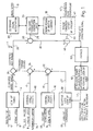
- Figure 1 shows in block schematic form, an apparatus 1 for quantifying the net torque produced by an internal combustion engine.
- An estimated gross torque 2 is generated in a look-up table 4 as a function of injected fuel quantity 6 and engine speed 8.
- external torque losses are taken to be those from an air conditioning unit and alternator (not shown), both driven by the engine.
- the load from the air conditioning unit will be fairly constant for a given engine speed, whilst the load from the alternator will depend on the alternator current.
- An external torque loss estimator 10 therefore receives three signals, engine speed 8, air conditioning on or off 12, and alternator current 14, and produces an output signal for an estimated external torque loss 17.
- An internal torque loss estimator 16 therefore receives inputs signals representing the engine speed 8 and the coolant temperature 18, and produces an output signal for an estimated internal torque loss 19.
- an adaptive loss look-up table 20 provides an output signal for a corrective torque loss 21, to be explained in more detail below.
- the inaccuracies may be due to many sources of error, these errors are generally a function of engine coolant temperature 18, and so the look-up table is arranged to provide a corrective torque loss signal depending upon an input of the coolant temperature 18.
- the external, internal and corrective torque loss signals 17,19,21 are summed at nodes 22, 24, and then subtracted from the estimated gross torque at node 26 to produce an estimated net torque signal 28.
- the estimated net torque should be zero. If the engine is not in a steady state, for example with the injected fuel quantity high or low for the particular engine speed, then the engine should be accelerating with either a positive or a negative estimated net torque.
- Any discrepancy between the engine acceleration and the estimated net torque under these conditions in which the engine is effectively disengaged from the drive wheels, may therefore be used to calculate an actual net torque 29, which may be subtracted 30 from the estimated net torque 28 to produce a torque loss correction signal 32.
- the actual net torque with the engine disengaged from the drive wheels is calculated 34 from a measured engine acceleration 36 and a known constant moment of inertia 38 for the engine (optionally adjusted for any accessories connected to the engine).
- the acceleration is calculated using the same engine speed signal 8 as used elsewhere in Figure 1.
- the torque converter loss estimator could, of course, equivalently be placed in the section of the figure with the external and internal torque loss, since an automatic transmission results in another form of external torque loss.
- the definition of the estimated net torque 28 would be the estimated net torque including torque converter losses.
- the torque converter loss estimator 40 is separate so that the circuitry in the case of a manual transmission is kept simple.
- the torque loss correction signal is then averaged 50 to reduce noise and transient signals, and then a torque loss correction value 51 is factored back into the adaptive loss look-up table if no engine power is being supplied to the wheels 52.
- Figure 2 shows how the apparatus 1 described above may be used in a power train control module 101 and with a diesel engine 102 in a vehicle having a traction control module 104 and an automatic transmission control module 106.
- the engine comprises known means 108 to measure engine speed, which although not illustrated are in the form of a toothed wheel and sensor arrangement on the engine crankshaft. These provide a plurality of pulses 110 for each revolution of the engine 102, to the acceleration determination module 36. The engine acceleration measurement is then used in the manner described above to produce the corrected net torque estimate, which is used in the calculations of fuel-to torque 114 and torque-to-fuel 112 for the fuel control system 116, as well as in the traction control 104 and automatic transmission control 106 modules in which the gearbox includes a sensor to detect if the gear box is in neutral in order to determine whether or not engine power is drawn through the gearbox.
- gearbox sensor 120 which detects if the gears are disengaged from the engine in order to determine whether or not engine power is drawn through the gearbox.
- the invention may therefore be used to obtain an accurate and convenient control over the fuel control system, according to the demands placed upon the engine by the driver, and the limitation or constraints required by the other controls such as traction control and automatic gearbox operation.
Landscapes
- Engineering & Computer Science (AREA)
- Chemical & Material Sciences (AREA)
- Combustion & Propulsion (AREA)
- Mechanical Engineering (AREA)
- General Engineering & Computer Science (AREA)
- Combined Controls Of Internal Combustion Engines (AREA)
- Control Of Vehicle Engines Or Engines For Specific Uses (AREA)
Applications Claiming Priority (2)
| Application Number | Priority Date | Filing Date | Title |
|---|---|---|---|
| GB9720742 | 1997-09-30 | ||
| GB9720742A GB2329713A (en) | 1997-09-30 | 1997-09-30 | IC engine net torque calculator |
Publications (3)
| Publication Number | Publication Date |
|---|---|
| EP0904972A2 true EP0904972A2 (fr) | 1999-03-31 |
| EP0904972A3 EP0904972A3 (fr) | 1999-07-21 |
| EP0904972B1 EP0904972B1 (fr) | 2002-11-27 |
Family
ID=10819841
Family Applications (1)
| Application Number | Title | Priority Date | Filing Date |
|---|---|---|---|
| EP98305839A Expired - Lifetime EP0904972B1 (fr) | 1997-09-30 | 1998-07-22 | Systéme et méthode de determination du couple de moteur |
Country Status (4)
| Country | Link |
|---|---|
| US (1) | US6035252A (fr) |
| EP (1) | EP0904972B1 (fr) |
| DE (1) | DE69809673T2 (fr) |
| GB (1) | GB2329713A (fr) |
Cited By (17)
| Publication number | Priority date | Publication date | Assignee | Title |
|---|---|---|---|---|
| EP1148274A1 (fr) * | 2000-04-18 | 2001-10-24 | Ford Global Technologies, Inc. | Procédé adaptatif pour déterminer le point de passage au couple positif dans une chaíne cinématique comprenant une transmission automatique |
| EP1148272A1 (fr) * | 2000-04-18 | 2001-10-24 | Ford Global Technologies, Inc. | Procédé d'estimation du couple d'un moteur à combustion interne |
| KR20020018964A (ko) * | 2000-09-04 | 2002-03-09 | 클라우스 포스, 게오르그 뮐러 | 엔진의 손실 모멘트 적용 방법 |
| WO2004048762A1 (fr) * | 2002-11-27 | 2004-06-10 | Ricardo Consulting Engineers Limited | Gestion amelioree du moteur |
| EP1378646A3 (fr) * | 2002-07-04 | 2007-09-26 | Calsonic Kansei Corporation | Système de commande de véhicule |
| WO2007117207A1 (fr) * | 2006-04-07 | 2007-10-18 | Scania Cv Ab (Publ) | Procédé d'ajustement de table de conversion et système de commande d'un injecteur d'un cylindre dans un moteur à combustion |
| FR2908463A1 (fr) * | 2006-11-10 | 2008-05-16 | Bosch Gmbh Robert | Procede d'adaptation d'un champ de caracteristiques. |
| EP1775451A3 (fr) * | 2005-10-17 | 2008-09-10 | Ford Global Technologies, LLC | Méthode pour l évaluation d' un couple de frottement |
| WO2009074474A3 (fr) * | 2007-12-11 | 2009-09-03 | Zf Friedrichshafen Ag | Procédé de détermination du couple d'un moteur à combustion interne, disponible sur le vilebrequin d'un véhicule automobile |
| EP1884756A4 (fr) * | 2005-05-09 | 2011-12-14 | A & D Co Ltd | Dispositif de mesure de moteur |
| EP2434133A1 (fr) * | 2010-09-27 | 2012-03-28 | CLAAS Selbstfahrende Erntemaschinen GmbH | Concept de commande d'un moteur et dispositif de commande de puissance d'un véhicule motorisé |
| EP2530287A1 (fr) * | 2011-05-30 | 2012-12-05 | Ford Global Technologies, LLC | Dispositif et procédé d'évaluation de couple de combustion d'un moteur à combustion interne |
| CN101725708B (zh) * | 2008-10-24 | 2013-09-04 | 通用汽车环球科技运作公司 | 一种用于在机电式变速器内控制液压控制系统的液压管线压力的方法 |
| FR3001784A1 (fr) * | 2013-02-01 | 2014-08-08 | Peugeot Citroen Automobiles Sa | Dispositif d'estimation du couple de pertes d'une boite de vitesses manuelle en fonction de la duree de fonctionnement d'un moteur thermique couple a elle |
| EP2241739A3 (fr) * | 2009-04-07 | 2018-07-04 | Denso Corporation | Contrôleur d'un moteur à combustion pour synchroniser le moteur durant l'arrêt |
| FR3103440A1 (fr) | 2019-11-26 | 2021-05-28 | Psa Automobiles Sa | Procede de determination du couple transmis par le moteur a la chaine de traction |
| CN114689327A (zh) * | 2022-04-29 | 2022-07-01 | 中国第一汽车股份有限公司 | 一种发动机特性的确定方法、装置、存储介质及电子设备 |
Families Citing this family (24)
| Publication number | Priority date | Publication date | Assignee | Title |
|---|---|---|---|---|
| DE19704841A1 (de) * | 1997-02-08 | 1998-08-13 | Itt Mfg Enterprises Inc | Verfahren und Vorrichtung zur Regelung der Längsdynamik eines Fahrzeugs |
| JP3396036B2 (ja) * | 1997-06-30 | 2003-04-14 | 三菱電機株式会社 | 自動車用制御装置 |
| US6188951B1 (en) * | 1999-09-23 | 2001-02-13 | Daimlerchrysler Corporation | Engine friction characterization |
| US6584391B2 (en) * | 2001-07-23 | 2003-06-24 | International Engine Intellectual Property Company, Llc | Engine torque calculation |
| SE519792C2 (sv) * | 2001-08-17 | 2003-04-08 | Volvo Lastvagnar Ab | Metod för estimering av massan hos ett fordon vilket framförs på en väg med en varierande lutning samt metod för estimering av lutningen av den väg där ett fordon framförs |
| US6655353B1 (en) * | 2002-05-17 | 2003-12-02 | General Motors Corporation | Cylinder deactivation engine control system with torque matching |
| JP4099653B2 (ja) * | 2002-11-08 | 2008-06-11 | 三菱ふそうトラック・バス株式会社 | 機械式変速機の変速制御装置 |
| US9052717B1 (en) * | 2004-02-11 | 2015-06-09 | Enovation Controls, Llc | Watercraft speed control device |
| US20080243321A1 (en) | 2005-02-11 | 2008-10-02 | Econtrols, Inc. | Event sensor |
| AU2004201718B1 (en) * | 2004-04-27 | 2005-02-24 | Larry Lin Feng Weng | Engine optimisation method and apparatus |
| US9207675B1 (en) | 2005-02-11 | 2015-12-08 | Enovation Controls, Llc | Event sensor |
| DE102005011027A1 (de) * | 2005-03-08 | 2006-09-14 | Robert Bosch Gmbh | Verfahren und Vorrichtung zum Betreiben einer Brennkraftmaschine |
| US7754969B2 (en) * | 2007-06-08 | 2010-07-13 | Southwire Company | Armored cable with integral support |
| FR2921453B1 (fr) * | 2007-09-25 | 2010-02-26 | Renault Sas | Procede d'assistance au demarrage en cote d'un vehicule motorise. |
| US8042325B2 (en) * | 2007-11-01 | 2011-10-25 | Ford Global Technologies, Llc | Adapting indicated engine torque during regeneration of a diesel particulate filter |
| US8050828B2 (en) * | 2008-03-31 | 2011-11-01 | GM Global Technology Operations LLC | Transmission oil measurement system and method |
| US7844404B2 (en) * | 2008-12-17 | 2010-11-30 | Honeywell International Inc. | Systems and methods for determining engine torque values |
| US8504261B2 (en) * | 2010-03-17 | 2013-08-06 | GM Global Technology Operations LLC | Powertrain control systems and methods with parameter transfer between an ECM and a TCM for ECM and TCM based control |
| JP5857950B2 (ja) * | 2012-12-19 | 2016-02-10 | トヨタ自動車株式会社 | 車両の制御装置 |
| DE102014016398A1 (de) * | 2014-11-05 | 2016-05-12 | Man Diesel & Turbo Se | Verfahren und Steuerungseinrichtung zum Betreiben einer Brennkraftmaschine |
| AT514725B1 (de) * | 2014-11-28 | 2016-06-15 | Avl List Gmbh | Verfahren und eine Vorrichtung zur Ermittlung des Vortriebsmoments |
| DE202015105177U1 (de) | 2015-09-30 | 2017-01-02 | Ebm-Papst St. Georgen Gmbh & Co. Kg | Anordnung zum Bestimmen eines Drucks |
| CN108571388B (zh) * | 2017-03-09 | 2022-02-11 | 罗伯特·博世有限公司 | 用于阻力矩适应的方法和装置 |
| CN109388775B (zh) * | 2017-08-14 | 2023-11-21 | 厦门雅迅网络股份有限公司 | 发动机损耗计算方法及发动机损耗计算装置 |
Family Cites Families (6)
| Publication number | Priority date | Publication date | Assignee | Title |
|---|---|---|---|---|
| JP2674077B2 (ja) * | 1988-04-12 | 1997-11-05 | トヨタ自動車株式会社 | 内燃機関の非線形フィードバック制御方法 |
| DE4304779B4 (de) * | 1992-06-20 | 2005-11-24 | Robert Bosch Gmbh | Vorrichtung zur Steuerung des von einer Antriebseinheit eines Fahrzeugs abzugebenden Drehmoments |
| DE4239711B4 (de) * | 1992-11-26 | 2005-03-31 | Robert Bosch Gmbh | Verfahren und Vorrichtung zur Steuerung eines Fahrzeugs |
| US5577474A (en) * | 1995-11-29 | 1996-11-26 | General Motors Corporation | Torque estimation for engine speed control |
| US5771482A (en) * | 1995-12-15 | 1998-06-23 | The Ohio State University | Estimation of instantaneous indicated torque in multicylinder engines |
| SE504717C2 (sv) * | 1996-02-07 | 1997-04-14 | Scania Cv Ab | Förfarande för korrigering av motormomentet vid växling |
-
1997
- 1997-09-30 GB GB9720742A patent/GB2329713A/en not_active Withdrawn
-
1998
- 1998-07-22 EP EP98305839A patent/EP0904972B1/fr not_active Expired - Lifetime
- 1998-07-22 DE DE69809673T patent/DE69809673T2/de not_active Expired - Fee Related
- 1998-09-29 US US09/163,119 patent/US6035252A/en not_active Expired - Fee Related
Cited By (23)
| Publication number | Priority date | Publication date | Assignee | Title |
|---|---|---|---|---|
| EP1148272A1 (fr) * | 2000-04-18 | 2001-10-24 | Ford Global Technologies, Inc. | Procédé d'estimation du couple d'un moteur à combustion interne |
| US6379283B1 (en) | 2000-04-18 | 2002-04-30 | Ford Global Technologies, Inc. | Torque estimation method for an internal combustion engine |
| EP1148274A1 (fr) * | 2000-04-18 | 2001-10-24 | Ford Global Technologies, Inc. | Procédé adaptatif pour déterminer le point de passage au couple positif dans une chaíne cinématique comprenant une transmission automatique |
| KR20020018964A (ko) * | 2000-09-04 | 2002-03-09 | 클라우스 포스, 게오르그 뮐러 | 엔진의 손실 모멘트 적용 방법 |
| EP1378646A3 (fr) * | 2002-07-04 | 2007-09-26 | Calsonic Kansei Corporation | Système de commande de véhicule |
| US7506536B2 (en) | 2002-11-27 | 2009-03-24 | Ricardo Uk Limited | Method of deriving engine cylinder mechanical top dead centre |
| WO2004048762A1 (fr) * | 2002-11-27 | 2004-06-10 | Ricardo Consulting Engineers Limited | Gestion amelioree du moteur |
| EP1884756A4 (fr) * | 2005-05-09 | 2011-12-14 | A & D Co Ltd | Dispositif de mesure de moteur |
| EP1775451A3 (fr) * | 2005-10-17 | 2008-09-10 | Ford Global Technologies, LLC | Méthode pour l évaluation d' un couple de frottement |
| WO2007117207A1 (fr) * | 2006-04-07 | 2007-10-18 | Scania Cv Ab (Publ) | Procédé d'ajustement de table de conversion et système de commande d'un injecteur d'un cylindre dans un moteur à combustion |
| EP2013463A4 (fr) * | 2006-04-07 | 2015-06-24 | Scania Cv Abp | Procédé d'ajustement de table de conversion et système de commande d'un injecteur d'un cylindre dans un moteur à combustion |
| US7991537B2 (en) | 2006-04-07 | 2011-08-02 | Scania Cv Ab | Method for adjusting a lookup table and a system for controlling an injector of a cylinder in a combustion engine |
| CN101438045B (zh) * | 2006-04-07 | 2012-01-04 | 斯堪尼亚有限公司 | 一种调整查找表的方法和控制内燃机中气缸的喷射器的系统 |
| FR2908463A1 (fr) * | 2006-11-10 | 2008-05-16 | Bosch Gmbh Robert | Procede d'adaptation d'un champ de caracteristiques. |
| WO2009074474A3 (fr) * | 2007-12-11 | 2009-09-03 | Zf Friedrichshafen Ag | Procédé de détermination du couple d'un moteur à combustion interne, disponible sur le vilebrequin d'un véhicule automobile |
| CN101725708B (zh) * | 2008-10-24 | 2013-09-04 | 通用汽车环球科技运作公司 | 一种用于在机电式变速器内控制液压控制系统的液压管线压力的方法 |
| EP2241739A3 (fr) * | 2009-04-07 | 2018-07-04 | Denso Corporation | Contrôleur d'un moteur à combustion pour synchroniser le moteur durant l'arrêt |
| EP2434133A1 (fr) * | 2010-09-27 | 2012-03-28 | CLAAS Selbstfahrende Erntemaschinen GmbH | Concept de commande d'un moteur et dispositif de commande de puissance d'un véhicule motorisé |
| EP2530287A1 (fr) * | 2011-05-30 | 2012-12-05 | Ford Global Technologies, LLC | Dispositif et procédé d'évaluation de couple de combustion d'un moteur à combustion interne |
| FR3001784A1 (fr) * | 2013-02-01 | 2014-08-08 | Peugeot Citroen Automobiles Sa | Dispositif d'estimation du couple de pertes d'une boite de vitesses manuelle en fonction de la duree de fonctionnement d'un moteur thermique couple a elle |
| FR3103440A1 (fr) | 2019-11-26 | 2021-05-28 | Psa Automobiles Sa | Procede de determination du couple transmis par le moteur a la chaine de traction |
| CN114689327A (zh) * | 2022-04-29 | 2022-07-01 | 中国第一汽车股份有限公司 | 一种发动机特性的确定方法、装置、存储介质及电子设备 |
| CN114689327B (zh) * | 2022-04-29 | 2025-06-27 | 中国第一汽车股份有限公司 | 一种发动机特性的确定方法、装置、存储介质及电子设备 |
Also Published As
| Publication number | Publication date |
|---|---|
| DE69809673D1 (de) | 2003-01-09 |
| GB9720742D0 (en) | 1997-12-03 |
| GB2329713A (en) | 1999-03-31 |
| DE69809673T2 (de) | 2003-04-10 |
| EP0904972A3 (fr) | 1999-07-21 |
| EP0904972B1 (fr) | 2002-11-27 |
| US6035252A (en) | 2000-03-07 |
Similar Documents
| Publication | Publication Date | Title |
|---|---|---|
| EP0904972B1 (fr) | Systéme et méthode de determination du couple de moteur | |
| US5325740A (en) | Arrangement for controlling the output power of a drive unit of a motor vehicle | |
| US7665558B2 (en) | Engine misfire detection apparatus, hybrid vehicle equipped with the same, and engine misfire detection method | |
| US6065449A (en) | Fuel injection control device for an internal combustion engine | |
| US20030017911A1 (en) | Engine torque calculation | |
| US6397152B1 (en) | Method and motor control apparatus for the correction of a computer-established torque in the drive train of a motor vehicle | |
| US6427109B1 (en) | Powertrain torque estimate | |
| US20040014558A1 (en) | Transmission control apparatus for an automatic transmission | |
| USRE34216E (en) | Method of and apparatus for controlling engine revolution speed | |
| US20080281502A1 (en) | Control apparatus for a source of rotational drive force | |
| KR100368712B1 (ko) | 자동변속기의제어방법및그제어장치및자동차 | |
| EP1323564B1 (fr) | Système de réglage pour véhicule hybride | |
| EP1148274B1 (fr) | Procédé adaptatif pour déterminer le point de passage au couple positif dans une chaíne cinématique comprenant une transmission automatique | |
| EP0535671B1 (fr) | Dispositif pour la commande de l'injection de carburant pour un moteur à combustion interne | |
| US7862469B2 (en) | Method for controlling a drivetrain of a motor vehicle | |
| US6568257B2 (en) | Cylinder air charge estimate | |
| US6317670B1 (en) | Control apparatus and method of automatic transmission | |
| JP2003090423A (ja) | 流体式トルクコンバータのタービントルク算出装置、車両の駆動トルク制御装置 | |
| US5935042A (en) | Adaptive K-factor to improve stall-torque management | |
| US6877480B2 (en) | Idle speed compensation in a pedal map | |
| US20070199322A1 (en) | Method and system for calculating brake torque produced by a turbocharged engine | |
| JP3699821B2 (ja) | 自動車の制御装置および制御方法 | |
| EP2199578B1 (fr) | Dispositif de contrôle de couple et procédé pour moteur à combustion interne | |
| JP3358624B2 (ja) | 内燃機関の燃料噴射制御装置 | |
| EP2183691B1 (fr) | Procédé et système pour calculer un couple de sortie produit par un moteur à turbocompresseur |
Legal Events
| Date | Code | Title | Description |
|---|---|---|---|
| PUAI | Public reference made under article 153(3) epc to a published international application that has entered the european phase |
Free format text: ORIGINAL CODE: 0009012 |
|
| AK | Designated contracting states |
Kind code of ref document: A2 Designated state(s): DE FR GB |
|
| AX | Request for extension of the european patent |
Free format text: AL;LT;LV;MK;RO;SI |
|
| PUAL | Search report despatched |
Free format text: ORIGINAL CODE: 0009013 |
|
| AK | Designated contracting states |
Kind code of ref document: A3 Designated state(s): AT BE CH CY DE DK ES FI FR GB GR IE IT LI LU MC NL PT SE |
|
| AX | Request for extension of the european patent |
Free format text: AL;LT;LV;MK;RO;SI |
|
| 17P | Request for examination filed |
Effective date: 19991224 |
|
| AKX | Designation fees paid |
Free format text: DE FR GB |
|
| RTI1 | Title (correction) |
Free format text: ENGINE TORQUE QUANTIFYING APPARATUS AND METHOD |
|
| GRAG | Despatch of communication of intention to grant |
Free format text: ORIGINAL CODE: EPIDOS AGRA |
|
| RTI1 | Title (correction) |
Free format text: ENGINE TORQUE QUANTIFYING APPARATUS AND METHOD |
|
| 17Q | First examination report despatched |
Effective date: 20020213 |
|
| GRAG | Despatch of communication of intention to grant |
Free format text: ORIGINAL CODE: EPIDOS AGRA |
|
| GRAH | Despatch of communication of intention to grant a patent |
Free format text: ORIGINAL CODE: EPIDOS IGRA |
|
| GRAH | Despatch of communication of intention to grant a patent |
Free format text: ORIGINAL CODE: EPIDOS IGRA |
|
| GRAA | (expected) grant |
Free format text: ORIGINAL CODE: 0009210 |
|
| AK | Designated contracting states |
Kind code of ref document: B1 Designated state(s): DE FR GB |
|
| REG | Reference to a national code |
Ref country code: GB Ref legal event code: FG4D |
|
| REF | Corresponds to: |
Ref document number: 69809673 Country of ref document: DE Date of ref document: 20030109 |
|
| ET | Fr: translation filed | ||
| PLBE | No opposition filed within time limit |
Free format text: ORIGINAL CODE: 0009261 |
|
| STAA | Information on the status of an ep patent application or granted ep patent |
Free format text: STATUS: NO OPPOSITION FILED WITHIN TIME LIMIT |
|
| 26N | No opposition filed |
Effective date: 20030828 |
|
| PGFP | Annual fee paid to national office [announced via postgrant information from national office to epo] |
Ref country code: FR Payment date: 20040721 Year of fee payment: 7 Ref country code: DE Payment date: 20040721 Year of fee payment: 7 |
|
| REG | Reference to a national code |
Ref country code: FR Ref legal event code: TP |
|
| PGFP | Annual fee paid to national office [announced via postgrant information from national office to epo] |
Ref country code: GB Payment date: 20050711 Year of fee payment: 8 |
|
| PG25 | Lapsed in a contracting state [announced via postgrant information from national office to epo] |
Ref country code: DE Free format text: LAPSE BECAUSE OF NON-PAYMENT OF DUE FEES Effective date: 20060201 |
|
| PG25 | Lapsed in a contracting state [announced via postgrant information from national office to epo] |
Ref country code: FR Free format text: LAPSE BECAUSE OF NON-PAYMENT OF DUE FEES Effective date: 20060331 |
|
| REG | Reference to a national code |
Ref country code: FR Ref legal event code: ST Effective date: 20060331 |
|
| PG25 | Lapsed in a contracting state [announced via postgrant information from national office to epo] |
Ref country code: GB Free format text: LAPSE BECAUSE OF NON-PAYMENT OF DUE FEES Effective date: 20060722 |
|
| GBPC | Gb: european patent ceased through non-payment of renewal fee |
Effective date: 20060722 |