EP0904792B1 - Spritzenhalter mit eingebautem Dosierungseinteiler - Google Patents
Spritzenhalter mit eingebautem Dosierungseinteiler Download PDFInfo
- Publication number
- EP0904792B1 EP0904792B1 EP98307470A EP98307470A EP0904792B1 EP 0904792 B1 EP0904792 B1 EP 0904792B1 EP 98307470 A EP98307470 A EP 98307470A EP 98307470 A EP98307470 A EP 98307470A EP 0904792 B1 EP0904792 B1 EP 0904792B1
- Authority
- EP
- European Patent Office
- Prior art keywords
- syringe
- stop
- end portion
- assembly
- holder
- Prior art date
- Legal status (The legal status is an assumption and is not a legal conclusion. Google has not performed a legal analysis and makes no representation as to the accuracy of the status listed.)
- Expired - Lifetime
Links
- 239000003814 drug Substances 0.000 claims description 14
- 229940079593 drug Drugs 0.000 claims description 13
- 239000012530 fluid Substances 0.000 claims description 9
- POIUWJQBRNEFGX-XAMSXPGMSA-N cathelicidin Chemical compound C([C@@H](C(=O)N[C@@H](CCCNC(N)=N)C(=O)N[C@@H](CCCCN)C(=O)N[C@@H](CO)C(=O)N[C@@H](CCCCN)C(=O)N[C@@H](CCC(O)=O)C(=O)N[C@@H](CCCCN)C(=O)N[C@@H]([C@@H](C)CC)C(=O)NCC(=O)N[C@@H](CCCCN)C(=O)N[C@@H](CCC(O)=O)C(=O)N[C@@H](CC=1C=CC=CC=1)C(=O)N[C@@H](CCCCN)C(=O)N[C@@H](CCCNC(N)=N)C(=O)N[C@@H]([C@@H](C)CC)C(=O)N[C@@H](C(C)C)C(=O)N[C@@H](CCC(N)=O)C(=O)N[C@@H](CCCNC(N)=N)C(=O)N[C@@H]([C@@H](C)CC)C(=O)N[C@@H](CCCCN)C(=O)N[C@@H](CC(O)=O)C(=O)N[C@@H](CC=1C=CC=CC=1)C(=O)N[C@@H](CC(C)C)C(=O)N[C@@H](CCCNC(N)=N)C(=O)N[C@@H](CC(N)=O)C(=O)N[C@@H](CC(C)C)C(=O)N[C@@H](C(C)C)C(=O)N1[C@@H](CCC1)C(=O)N[C@@H](CCCNC(N)=N)C(=O)N[C@@H]([C@@H](C)O)C(=O)N[C@@H](CCC(O)=O)C(=O)N[C@@H](CO)C(O)=O)NC(=O)[C@H](CC=1C=CC=CC=1)NC(=O)[C@H](CC(O)=O)NC(=O)CNC(=O)[C@H](CC(C)C)NC(=O)[C@@H](N)CC(C)C)C1=CC=CC=C1 POIUWJQBRNEFGX-XAMSXPGMSA-N 0.000 description 9
- 238000006073 displacement reaction Methods 0.000 description 4
- 230000035515 penetration Effects 0.000 description 4
- 210000002105 tongue Anatomy 0.000 description 3
- 230000000295 complement effect Effects 0.000 description 2
- 230000000875 corresponding effect Effects 0.000 description 2
- 238000003780 insertion Methods 0.000 description 2
- 230000037431 insertion Effects 0.000 description 2
- 239000004743 Polypropylene Substances 0.000 description 1
- 238000010276 construction Methods 0.000 description 1
- 230000002596 correlated effect Effects 0.000 description 1
- 238000001746 injection moulding Methods 0.000 description 1
- 238000004519 manufacturing process Methods 0.000 description 1
- 239000000463 material Substances 0.000 description 1
- 230000013011 mating Effects 0.000 description 1
- 238000002483 medication Methods 0.000 description 1
- 238000012986 modification Methods 0.000 description 1
- 230000004048 modification Effects 0.000 description 1
- 239000000825 pharmaceutical preparation Substances 0.000 description 1
- 229940127557 pharmaceutical product Drugs 0.000 description 1
- 239000004033 plastic Substances 0.000 description 1
- -1 polypropylene Polymers 0.000 description 1
- 229920001155 polypropylene Polymers 0.000 description 1
- 229940071643 prefilled syringe Drugs 0.000 description 1
- 238000007789 sealing Methods 0.000 description 1
Images


Classifications
-
- A—HUMAN NECESSITIES
- A61—MEDICAL OR VETERINARY SCIENCE; HYGIENE
- A61M—DEVICES FOR INTRODUCING MEDIA INTO, OR ONTO, THE BODY; DEVICES FOR TRANSDUCING BODY MEDIA OR FOR TAKING MEDIA FROM THE BODY; DEVICES FOR PRODUCING OR ENDING SLEEP OR STUPOR
- A61M5/00—Devices for bringing media into the body in a subcutaneous, intra-vascular or intramuscular way; Accessories therefor, e.g. filling or cleaning devices, arm-rests
- A61M5/178—Syringes
- A61M5/31—Details
- A61M5/315—Pistons; Piston-rods; Guiding, blocking or restricting the movement of the rod or piston; Appliances on the rod for facilitating dosing ; Dosing mechanisms
- A61M5/31565—Administration mechanisms, i.e. constructional features, modes of administering a dose
- A61M5/31576—Constructional features or modes of drive mechanisms for piston rods
- A61M5/31578—Constructional features or modes of drive mechanisms for piston rods based on axial translation, i.e. components directly operatively associated and axially moved with plunger rod
- A61M5/3158—Constructional features or modes of drive mechanisms for piston rods based on axial translation, i.e. components directly operatively associated and axially moved with plunger rod performed by axially moving actuator operated by user, e.g. an injection button
-
- A—HUMAN NECESSITIES
- A61—MEDICAL OR VETERINARY SCIENCE; HYGIENE
- A61M—DEVICES FOR INTRODUCING MEDIA INTO, OR ONTO, THE BODY; DEVICES FOR TRANSDUCING BODY MEDIA OR FOR TAKING MEDIA FROM THE BODY; DEVICES FOR PRODUCING OR ENDING SLEEP OR STUPOR
- A61M15/00—Inhalators
- A61M15/0001—Details of inhalators; Constructional features thereof
- A61M15/0021—Mouthpieces therefor
- A61M15/0025—Mouthpieces therefor with caps
- A61M15/0026—Hinged caps
-
- A—HUMAN NECESSITIES
- A61—MEDICAL OR VETERINARY SCIENCE; HYGIENE
- A61M—DEVICES FOR INTRODUCING MEDIA INTO, OR ONTO, THE BODY; DEVICES FOR TRANSDUCING BODY MEDIA OR FOR TAKING MEDIA FROM THE BODY; DEVICES FOR PRODUCING OR ENDING SLEEP OR STUPOR
- A61M5/00—Devices for bringing media into the body in a subcutaneous, intra-vascular or intramuscular way; Accessories therefor, e.g. filling or cleaning devices, arm-rests
- A61M5/178—Syringes
- A61M5/31—Details
- A61M5/3129—Syringe barrels
-
- A—HUMAN NECESSITIES
- A61—MEDICAL OR VETERINARY SCIENCE; HYGIENE
- A61M—DEVICES FOR INTRODUCING MEDIA INTO, OR ONTO, THE BODY; DEVICES FOR TRANSDUCING BODY MEDIA OR FOR TAKING MEDIA FROM THE BODY; DEVICES FOR PRODUCING OR ENDING SLEEP OR STUPOR
- A61M5/00—Devices for bringing media into the body in a subcutaneous, intra-vascular or intramuscular way; Accessories therefor, e.g. filling or cleaning devices, arm-rests
- A61M5/178—Syringes
- A61M5/31—Details
- A61M5/315—Pistons; Piston-rods; Guiding, blocking or restricting the movement of the rod or piston; Appliances on the rod for facilitating dosing ; Dosing mechanisms
- A61M5/31525—Dosing
-
- A—HUMAN NECESSITIES
- A61—MEDICAL OR VETERINARY SCIENCE; HYGIENE
- A61M—DEVICES FOR INTRODUCING MEDIA INTO, OR ONTO, THE BODY; DEVICES FOR TRANSDUCING BODY MEDIA OR FOR TAKING MEDIA FROM THE BODY; DEVICES FOR PRODUCING OR ENDING SLEEP OR STUPOR
- A61M15/00—Inhalators
- A61M15/08—Inhaling devices inserted into the nose
-
- A—HUMAN NECESSITIES
- A61—MEDICAL OR VETERINARY SCIENCE; HYGIENE
- A61M—DEVICES FOR INTRODUCING MEDIA INTO, OR ONTO, THE BODY; DEVICES FOR TRANSDUCING BODY MEDIA OR FOR TAKING MEDIA FROM THE BODY; DEVICES FOR PRODUCING OR ENDING SLEEP OR STUPOR
- A61M5/00—Devices for bringing media into the body in a subcutaneous, intra-vascular or intramuscular way; Accessories therefor, e.g. filling or cleaning devices, arm-rests
- A61M5/178—Syringes
- A61M5/31—Details
- A61M5/315—Pistons; Piston-rods; Guiding, blocking or restricting the movement of the rod or piston; Appliances on the rod for facilitating dosing ; Dosing mechanisms
- A61M5/31501—Means for blocking or restricting the movement of the rod or piston
- A61M5/31505—Integral with the syringe barrel, i.e. connected to the barrel so as to make up a single complete piece or unit
-
- A—HUMAN NECESSITIES
- A61—MEDICAL OR VETERINARY SCIENCE; HYGIENE
- A61M—DEVICES FOR INTRODUCING MEDIA INTO, OR ONTO, THE BODY; DEVICES FOR TRANSDUCING BODY MEDIA OR FOR TAKING MEDIA FROM THE BODY; DEVICES FOR PRODUCING OR ENDING SLEEP OR STUPOR
- A61M5/00—Devices for bringing media into the body in a subcutaneous, intra-vascular or intramuscular way; Accessories therefor, e.g. filling or cleaning devices, arm-rests
- A61M5/178—Syringes
- A61M5/31—Details
- A61M5/315—Pistons; Piston-rods; Guiding, blocking or restricting the movement of the rod or piston; Appliances on the rod for facilitating dosing ; Dosing mechanisms
- A61M5/31565—Administration mechanisms, i.e. constructional features, modes of administering a dose
- A61M5/31566—Means improving security or handling thereof
- A61M5/31571—Means preventing accidental administration
-
- A—HUMAN NECESSITIES
- A61—MEDICAL OR VETERINARY SCIENCE; HYGIENE
- A61M—DEVICES FOR INTRODUCING MEDIA INTO, OR ONTO, THE BODY; DEVICES FOR TRANSDUCING BODY MEDIA OR FOR TAKING MEDIA FROM THE BODY; DEVICES FOR PRODUCING OR ENDING SLEEP OR STUPOR
- A61M5/00—Devices for bringing media into the body in a subcutaneous, intra-vascular or intramuscular way; Accessories therefor, e.g. filling or cleaning devices, arm-rests
- A61M5/178—Syringes
- A61M5/31—Details
- A61M5/315—Pistons; Piston-rods; Guiding, blocking or restricting the movement of the rod or piston; Appliances on the rod for facilitating dosing ; Dosing mechanisms
- A61M5/31565—Administration mechanisms, i.e. constructional features, modes of administering a dose
- A61M5/3159—Dose expelling manners
- A61M5/31593—Multi-dose, i.e. individually set dose repeatedly administered from the same medicament reservoir
- A61M5/31595—Pre-defined multi-dose administration by repeated overcoming of means blocking the free advancing movement of piston rod, e.g. by tearing or de-blocking
Definitions
- the field of the invention relates to devices for the administration of medication and, more particularly, to nasal syringes in which the travel of the plunger is controlled by a stop mechanism.
- Nasal syringes of more conventional construction include a cylindrical barrel having a blunt tip portion for insertion into a nostril.
- a piston is positioned within the barrel.
- a plunger extends from the end of the barrel opposite to the blunt tip. The position of the piston within the barrel is controlled by the plunger.
- a flange may be provided on one end of the plunger to facilitate its use.
- Nasal syringes are often supplied to users pre-filled with medication. Whether pre-filled or not, it may be desirable to administer selected, and usually equal volumes of medication to each nostril.
- U.S. Patent No. 4,962,868 discloses the use of a telescoping tube assembly which is designed for expelling the contents of a nasal syringe in two controlled doses.
- FR -A-783 520 shows the features of the preamble of claim 1.
- syringes While syringes often include graduations, it remains difficult for users to administer equal doses of medication to each nostril using conventional syringes. As such syringes are relatively inexpensive to manufacture and pre-fill, and are mass-produced, they have certain advantages over syringes which may be specifically designed for self-administration.
- the invention is directed to a holder for a syringe and an assembly which allows the use of a conventional, pre-filled syringe while providing control of the dose to be administered.
- the assembly is particularly applicable to nasal syringes where it is often desirable to dispense medication in two equal doses.
- a holder for a syringe according to claim 1 is provided by the invention.
- the holder includes an elongate body which includes a cavity in which the barrel of a syringe can be positioned.
- a stop is pivotably secured to one end portion of the elongate body, and is movable between first and second rotational positions. When in the first position, the stop adjoins the longitudinal axis-of the holder. It accordingly is engageable with the flange of a syringe plunger extending from the holder when in this position.
- an assembly which includes a syringe holder as defined in claim 1, a syringe mounted into the syringe holder, and a stop which is movably coupled to the syringe holder.
- the syringe includes a barrel, a first end extending from the barrel and including an opening for dispensing fluid from the barrel, a piston slidably positioned within the barrel, and a plunger engageable with the piston.
- the stop is manually movable between a first position where it engages the plunger after the plunger has been moved a preselected axial distance, and a second position where the plunger and stop are not engageable.
- the syringe can then be removed from the holder and discarded, or it can be discarded with the holder.
- the invention further provides an assembly for the nasal administration of fluids which limits the penetration of a syringe tip into a nostril.
- the assembly includes a syringe holder as defined in claim 1 and a nasal syringe mounted into the syringe holder.
- the nasal syringe includes a blunt tip having a smaller diameter than the average nostril. It projects from a blunt end of the holder which is larger in diameter than that of an average nostril
- the nasal syringe is maintained in the holder such that the blunt tip thereof cannot extend more than a selected distance beyond the blunt end of the holder.
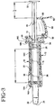
- An assembly 10 including a syringe holder 12 and a syringe 14 is provided.
- the assembly allows the dose delivered by the syringe to be divided. It further limits the penetration of the syringe tip into the body.
- the syringe holder is comprised of a tubular body 16 and an end cap 18.
- the syringe is comprised of a cylindrical barrel 20 having a blunt tip 22 including an orifice 24 through which fluid can be expelled, a piston 26 (shown in Fig. 3), and a plunger 28.
- the rear end of the syringe barrel includes a flange 30.
- a finger tab 32 is also integrally formed at one end of the plunger 28.
- the piston 26 and plunger 28 are preferably separate components, and can be engaged or connected with one another after the syringe barrel has been mounted within the syringe holder, or if desired, they can be engaged or connected together prior to mounting the syringe barrel in the syringe holder.
- the syringe is preferably pre-filled with medication prior to inserting it within the syringe holder.
- a sealing cap 33 may be fitted over the blunt tip 22 to prevent the loss of fluid through the orifice 24 prior to use of the assembly.
- the tubular body 16 of the holder is ergonomically shaped to facilitate handling. It is preferably made from a plastic material such as polypropylene.
- the body 16 includes a first, enlarged end portion 16A through which the blunt tip 22 of the syringe can extend, and a second end portion 16B including radially outwardly extending flanges 34. These flanges are larger than that provided on the syringe barrel, and make the assembly more convenient for the user to operate than the syringe alone.
- the end face of the front end portion 16A is larger in diameter than the diameter of an average adult nostril, and is blunt. While the embodiment shown in the drawings has a front end face which is rounded, it may alternatively be oval or any other shape desired, provided that the front end face is prevented from entry into the nostril.
- One or more transparent windows 36 are provided in the tubular body 16 of the syringe holder.
- the windows may be in the form of openings in the tubular body, or transparent wall portions mounted to the tubular body.
- the windows allow the user to view the syringe barrel 20 located within the holder. The user can accordingly determine whether there is any fluid present in the syringe, and whether the fluid is suitable for administration. As some pharmaceutical products are frozen during storage, it may be important to determine whether the product within the syringe has thawed prior to administration.
- the second end portion 16B of the holder is designed to retain flange 30 of the syringe barrel as well as a portion of the end cap 18.
- Second end portion 16B includes an end face defining an opening of sufficient size for receiving the syringe barrel, but which is smaller in size than flange 30.
- the flange 30 accordingly bears against this end face when the syringe is mounted to the holder.
- the inner surface of the tubular body 16 includes a plurality of axially extending ribs 16C. The ribs extend between the annular surface which forms the end face 16D of the first end portion 16A of the body and the end face 16E of the second end portion 16B thereof.
- Flange 30 of the syringe barrel thus bears against the ends of the ribs 16C, which may be considered part of one end face 16E of the tubular body.
- the ribs thus help to form the end face for supporting flange 30 of the syringe barrel.
- ribs 16C can serve to strengthen the structure of the syringe holder, and aids in the injection molding characteristics of the holder.
- a plurality of projections extend axially from the rear end face of the syringe holder, defining a generally cylindrical extension of the tubular body 16.
- a pair of opposing projections 38, 40 include detents 42, 44 for retaining the end cap 18.
- the detents include angled end faces which allow the end cap to snap behind the detents. Shoulder portions defined by the inner surfaces of the detents lock the end cap in place.
- the remaining projections 45 prevent the radial displacement of the end cap and obscure the syringe flange 30.
- the end cap 18 includes a generally annular body 46 having a central opening 48 aligned with the longitudinal axes of the syringe holder and syringe. Central opening 48 preferably displays a diameter less than the outer diameter of piston 26 so as to prevent piston 26 from inadvertent withdrawal from cylindrical barrel 20.
- a plurality of deflectable tabs 50 extend axially towards the syringe, and bear against the end face of the syringe flange 30. The flange 30 is accordingly locked in position between the tabs and the end face of the second end portion 16B of the syringe holder.
- the end cap further includes an axially extending projection 52 which functions as a detent in a manner described below. Projection 52 extends from a radial projection 53 having an opening 53A which receives one of the projections 38, 40 extending from the tubular body.
- a stop 54 which functions as a dose divider, is coupled to the end cap 18 by a hinge 56.
- Hinge 56 can be formed in any manner known to the skilled artisan, such a a pivot, for instance. Here, it is depicted as a so-called "living hinge" connecting end cap 18 and stop 54.
- Stop 54 includes a hook-like projection 58 near one end and end cap 18 includes a complementary projection 52, which likewise can assume a hooked structure. Stop 54 is engageable with the projection 52 of the end cap as the stop is pivoted towards the end cap in the locked position.
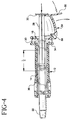
- the opposite end of stop 54 includes a stop surface 60 which is engageable with the plunger flange 32, as shown in Fig. 4.
- a finger tab 62 is also provided at this end for manually rotating the stop about the hinge 56.
- body portion 64 of the stop can be formed as a partial frustoconical.
- Syringe 14 is preferably filled and stoppered prior to its insertion into the tubular body 16 of the syringe holder 12.
- the syringe flange 30 is configured such that it engages end face 16E of the tubular body. Upon such engagement, the tip 22 of the syringe extends a selected distance beyond the enlarged end 16A of the tubular body. This-feature limits the penetration of the tip into a nostril of the patient when the assembly is employed.
- the end cap 18 is snapped into place behind the detents 42, 44, thereby locking syringe 14 in the holder 12.
- the flexible tabs 50 bear against the syringe flange 30, as shown in Fig. 3.
- the engagement of one of projections 38 or 40 in opening 53A of the end cap serves to prevent inadvertent rotation of the end cap with respect to syringe holder 16, thereby ensuring uniform orientation of the end cap during administration of the drug.
- plunger rod 28 is moved through the opening 48 in the end cap and into engagement with the piston 26. It will be understood that if it is desired to preassemble plunger 28 to syringe 14 before placement in holder 12, then an appropriate opening (not shown) can be incorporated in end cap 18 to allow lateral displacement vis-à-vis plunger 28. The assembly is ready for use upon engaging projections 52 and 58, locking the stop 54 into the position shown in Fig. 3, whereby the stop surface 60 is relatively close to the longitudinal axes of the holder and syringe and in position to engage the plunger flange 32.
- the assembly 10 as shown in Fig. 3 is grasped by the user and the blunt tip 22 inserted into a nostril
- the plunger 28 is then pushed into the syringe, causing the displacement of the piston 26 and expulsion of a predetermined contents of the syringe barrel through the orifice 24, depending upon the distance that finger tab 32 of the plunger rod travels until its progress is arrested by stop 60, as shown in Fig. 4.
- the total distance that piston 26 may be displaced into syringe 14 is depicted by the legend "L" on Figure 3, with that distance "L” also correlated to a total quantity of drug held by the syringe barrel.
- the displacement of piston 26 a distance L/n correlates to a first desired quantity of the drug to be administered from the syringe during a first motion of plunger 28.
- L/n would correlate to L/2).
- Fig. 5 shows the assembly 10 once the contents have been expelled. Once so used, the entire assembly is typically discarded.
- Figures 10 and 11 illustrate an alternate way to affix the end cap to the syringe holder.
- identical elements to the embodiment shown in Figures 1-9 have been correspondingly numbered, save for the addition of the numeral "1".
- end cap 118 includes a generally annular body 146 that includes a cylindrical wall 147.
- end cap 118 includes a central opening 148 and a plurality of deflectable tabs 150.
- Second end portion 116B of holder 112 is structured to include a cylindrical wall 119. Cylindrical walls 119, 147 of the holder and end cap are configured for locking/mating contact with one another.
- groove 121 is formed in cylindrical wall 119 that is complementary to a plurality of tongues 149 provided on cylindrical wall 147. Tongues 149 are engaged by groove 121.
- Groove 121 can be interrupted, such as by providing stops 123, to prevent end cap 118 from inadvertent rotation about holder 112.
- the assembly 10 provides a number of advantageous features. It allows the user to easily divide the dose to be delivered by the syringe through manipulation of an integral stop.
- the enlarged end of the syringe holder limits the penetration of the syringe tip into the nostril
- the configuration of the holder together with its enlarged flanges facilitate its handling and use. Manipulation of the stop is possible with one finger, while the assembly requires the use of only one hand.
Landscapes
- Health & Medical Sciences (AREA)
- Engineering & Computer Science (AREA)
- Animal Behavior & Ethology (AREA)
- Anesthesiology (AREA)
- Biomedical Technology (AREA)
- Heart & Thoracic Surgery (AREA)
- Hematology (AREA)
- Life Sciences & Earth Sciences (AREA)
- General Health & Medical Sciences (AREA)
- Public Health (AREA)
- Veterinary Medicine (AREA)
- Vascular Medicine (AREA)
- Pulmonology (AREA)
- Bioinformatics & Cheminformatics (AREA)
- Infusion, Injection, And Reservoir Apparatuses (AREA)
Claims (16)
- Halter (12) für eine Spritze, der folgendes umfaßt:einen länglichen Körper (16) mit einem stumpfen Endabschnitt (16A), der eine erste Öffnung einschließt, einen zweiten Endabschnitt (16B), der einen sich in Radialrichtung nach außen erstreckenden Flansch (34) einschließt und eine zweite Öffnung definiert, und einen Hohlraum zwischen dem stumpfen Endabschnitt und dem zweiten Endabschnitt einschließt, wobei der längliche Körper eine sich durch die erste und die zweite Öffnung erstreckende Längsachse und einen Anschlag hat, dadurch gekennzeichnet, daßder Anschlag (54) schwenkbar an dem zweiten Endabschnitt (16B) des länglichen Körpers gesichert ist und sich außerhalb des länglichen Körpers erstreckt, wobei der Anschlag zu der Längsachse hin und von derselben weg geschwenkt werden kann zwischen einer ersten Position, in der sich ein Abschnitt des Anschlags an die Längsachse anfügt, und einer zweiten Position, in welcher der Anschlag gegenüber der Längsachse verschoben ist.
- Halter nach Anspruch 1, der folgendes umfaßt:Mittel (50) zum Festhalten eines Spritzenflanschs an dem zweiten Endabschnitt und/oderwobei der längliche Körper ein röhrenförmiges Gehäuse und eine an dem röhrenförmigen Gehäuse gesicherte Kappe (18) einschließt, wobei die Kappe an dem zweiten Endabschnitt angeordnet ist und eine elastische Zunge (52) einschließt, die sich zu dem Hohlraum hin erstreckt, und/oderwobei der Anschlag (54) ein erstes Eingriffselement (58) einschließt und der längliche Körper ein zweites Eingriffselement (52) einschließt, wobei das erste und das zweite Eingriffselement in Eingriff gebracht sind, wenn sich der Anschlag in der ersten Position befindet, wodurch der Anschlag in der ersten Position gehalten wird, und/oderwobei der längliche Körper aus einem röhrenförmigen Gehäuse (16) und einer an dem röhrenförmigen Gehäuse gesicherten Kappe (18) besteht, wobei die Kappe an dem zweiten Endabschnitt angeordnet ist und eine mit der Längsachse ausgerichtete Öffnung (48) einschließt, wobei der Anschlag (54) schwenkbar an der Kappe gesichert ist.
- Baugruppe zum Spenden eines Medikaments, die folgendes umfaßt:einen Spritzenhalter nach Anspruch 1 oder Anspruch 2,eine an dem Spritzenhalter angebrachte Spritze (14), wobei die Spritze einen Zylinder (20), ein erstes Ende (22), das sich von dem Zylinder jenseits des Spritzenhalters erstreckt, wobei das erste Ende eine Öffnung (24) zum Spenden eines Fluids aus dem Zylinder einschließt, einen innerhalb des Zylinders verschiebbar angeordneten Kolben (26) und einen Tauchkolben (28), der mit dem Kolben in Eingriff gebracht werden kann, wobeider Tauchkolben mit dem Anschlag in Eingriff gebracht werden kann in der ersten Position bei Bewegen um eine vorgewählte Strecke in Axialrichtung und der Tauchkolben und der Anschlag in der zweiten Position nicht in Eingriff gebracht werden können.
- Baugruppe nach Anspruch 3, wobei:der Tauchkolben (28) einen Flansch (30) einschließt, wobei der Anschlag mit dem Flansch in Eingriff gebracht werden kann, wenn er sich in der ersten Position befindet.
- Baugruppe nach Anspruch 3 oder 4, wobei das erste Ende der Spritze stumpf ist,
- Baugruppe nach Anspruch 3, 4 oder 5, wobei der Anschlag (54) schwenkbar an den Spritzenhalter gekoppelt ist und von Hand zwischen der ersten und der zweiten Position bewegt werden kann.
- Baugruppe nach Anspruch 3 bis 6, wobei der Halter ein offenes Ende, durch das sich der Tauchkolben erstreckt, und einen sich in Radialrichtung nach außen erstreckenden Flansch (34), der sich an das offene Ende anfügt, einschließt.
- Baugruppe nach Anspruch 3 bis 7, wobei die vorgewählte Strecke in Axialrichtung etwa einer Dosierung eines in dem Spritzenzylinder festgehaltenen Medikaments entspricht, das in einer ersten Bewegung des Kolbens zu verabreichen gewünscht wird, und die vorgewählte Strecke in Axialrichtung etwa der halben Strecke entspricht, um die der Kolben imstande ist innerhalb des Zylinders zu bewegen, um etwa eine Hälfte der in dem Spritzenzylinder enthaltenen Dosis zu verabreichen.
- Baugruppe nach Anspruch 3 bis 8, wobei der Spritzenhalter folgendes umfaßt:einen röhrenförmigen Körper (16), der einen ersten Endabschnitt (16A), durch den das erste Ende der Spritze vorspringt, und einen zweiten Endabschnitt (16B) hat, undeine an dem zweiten Endabschnitt angebrachte Kappe (18), wobei der Anschlag (54) schwenkbar an der Kappe gesichert ist, wobei sich der Tauchkolben der Spritze durch die Kappe erstreckt.
- Baugruppe nach Anspruch 3 bis 9, wobei der Anschlag (54) ein erstes Ende, das schwenkbar an dem Spritzenhalter gesichert ist, und ein zweites Ende einschließt, das eine Anschlagfläche (60) einschließt, wobei der Tauchkolben einen Flansch (30) einschließt, der mit der Anschlagfläche in Eingriff gebracht werden kann, wenn sich der Anschlag in der ersten Position befindet, und Mittel (52, 58), um den Anschlag in der ersten Position zu halten.
- Baugruppe nach Anspruch 9 oder 10, wobei:der zweite Endabschnitt (16B) des röhrenförmigen Körpers einen sich in Radialrichtung nach außen erstreckenden Flansch (34) einschließt und die Kappe (18) eine Öffnung (48) einschließt, durch die sich die Tauchkolbenstange erstreckt, und eine flexible Zunge (50), die an der Spritze anliegt, und die Öffnung in der Kappe kleiner ist als ein Außendurchmesser des Kolbens, um zu verhindern, daß der Kolben unbeabsichtigt aus dem Zylinder herausgezogen wird.
- Baugruppe zum nasalen Verabreichen von Fluids, die folgendes umfaßt:einen Spritzenhalter nach Anspruch 1 oder Anspruch 2,eine vorgefüllte, an dem Spritzenhalter angebrachte, Nasenspritze (14), wobei die Nasenspritze einen innerhalb des Hohlraums angeordneten Zylinder (20), ein erstes Ende (22), das eine stumpfe Spitze und eine Öffnung (24) in der stumpfen Spitze zum Spenden eines Fluids aus dem Zylinder hat, ein zweites offenes Ende, einen Kolben (26) innerhalb des Zylinders und einen Tauchkolben (28) einschließt, der teilweise innerhalb des Zylinders angeordnet ist und sich über den zweiten Endabschnitt der Nasenspritze hinaus erstreckt, wobei der Tauchkolben ein Ende einschließt, das sich jenseits des zweiten Endabschnitts der Spritze erstreckt,wobei der stumpfe Endabschnitt des Spritzenhalters einen Durchmesser hat, der größer ist als der Durchschnittsdurchmesser eines Nasenlochs eines erwachsenen Patienten, wobei sich die stumpfe Spitze der Nasenspritze jenseits des stumpfen Endabschnitts des Spitzenhalters erstreckt und durch den Spritzenhalter daran gehindert wird, sich um eine vorgewählte Strecke über den stumpfen Endabschnitt hinaus zu erstrecken, wobei die stumpfe Spitze der Nasenspritze einen Durchmesser hat, der kleiner ist als der Durchschnittsdurchmesser eines Nasenlochs einer erwachsenen Person.
- Baugruppe nach Anspruch 11, wobei der zweite Endabschnitt des Spritzenhalters einen sich in Radialrichtung nach außen erstreckenden Flansch (34) einschließt.
- Baugruppe nach Anspruch 12, die einen Anschlag (54), der schwenkbar an dem Spritzenhalter angebracht ist und bewegt werden kann zwischen einer ersten Position, in welcher der Anschlag mit dem Tauchkolben in Eingriff gebracht werden kann, und einer zweiten Position, in welcher der Anschlag nicht mit dem Tauchkolben in Eingriff gebracht werden kann, und Mittel (52, 58), um den Anschlag in der ersten Position zu halten, einschließt.
- Baugruppe nach Anspruch 13, wobei der Anschlag (54) ein erstes Ende, das schwenkbar an dem Spritzenhalter gesichert ist, und ein zweites Ende einschließt, das eine Fingerzunge einschließt.
- Baugruppe nach Anspruch 14, die eine an dem zweiten Endabschnitt des länglichen Körperabschnitts gesicherte Kappe (18) einschließt, wobei die Nasenspritze einen zwischen der Kappe und dem zweiten Endabschnitt angeordneten Flansch (30) einschließt.
Applications Claiming Priority (2)
| Application Number | Priority Date | Filing Date | Title |
|---|---|---|---|
| US08/936,370 US5951526A (en) | 1997-09-24 | 1997-09-24 | Syringe holder with integral dose divider |
| US936370 | 1997-09-24 |
Publications (3)
| Publication Number | Publication Date |
|---|---|
| EP0904792A2 EP0904792A2 (de) | 1999-03-31 |
| EP0904792A3 EP0904792A3 (de) | 2001-12-05 |
| EP0904792B1 true EP0904792B1 (de) | 2006-05-10 |
Family
ID=25468536
Family Applications (1)
| Application Number | Title | Priority Date | Filing Date |
|---|---|---|---|
| EP98307470A Expired - Lifetime EP0904792B1 (de) | 1997-09-24 | 1998-09-15 | Spritzenhalter mit eingebautem Dosierungseinteiler |
Country Status (4)
| Country | Link |
|---|---|
| US (1) | US5951526A (de) |
| EP (1) | EP0904792B1 (de) |
| JP (1) | JP4170467B2 (de) |
| DE (1) | DE69834461T2 (de) |
Cited By (1)
| Publication number | Priority date | Publication date | Assignee | Title |
|---|---|---|---|---|
| EP4168067A1 (de) * | 2020-06-17 | 2023-04-26 | Credence Medsystems, Inc. | System und verfahren zur mikrodosisinjektion |
Families Citing this family (47)
| Publication number | Priority date | Publication date | Assignee | Title |
|---|---|---|---|---|
| AU141122S (en) * | 1998-05-13 | 2000-07-13 | Merck Serono Sa | Syringe holder |
| DE29912965U1 (de) | 1999-07-24 | 1999-09-16 | Hoelzle Dieter Tech Projekte | Injektionsvorrichtung |
| USD463546S1 (en) | 1999-10-14 | 2002-09-24 | Becton Dickinson And Company | Drug container holder |
| US6382204B1 (en) | 1999-10-14 | 2002-05-07 | Becton Dickinson And Company | Drug delivery system including holder and drug container |
| USD447559S1 (en) | 1999-10-14 | 2001-09-04 | Becton, Dickinson And Company | Drug container holder |
| USD446578S1 (en) | 1999-10-14 | 2001-08-14 | Becton, Dickinson And Company | Drug container holder |
| USD448474S1 (en) | 1999-10-14 | 2001-09-25 | Becton, Dickinson And Company | Drug container holder |
| AU2001241584B2 (en) * | 2000-02-23 | 2005-04-14 | Hospira, Inc. | Syringes and syringe systems for selectively dispensing controlled amounts of a therapeutic substance |
| JP4911867B2 (ja) * | 2001-04-10 | 2012-04-04 | ベクトン・ディキンソン・アンド・カンパニー | ホルダ及び薬剤容器を含む薬剤送出システム |
| GB2377176B (en) * | 2001-06-30 | 2004-10-20 | John Leyshon Maddocks | Devices for administering material |
| FR2829690B1 (fr) * | 2001-09-19 | 2003-12-19 | Inoteb | Dispositif de mise en place d'un biomateriau |
| FR2845016B1 (fr) * | 2002-09-27 | 2004-12-03 | Becton Dickinson France | Dispositif de pulverisation ou d'injection permettant de delivrer au moins deux doses determinees de produit |
| US7329241B2 (en) * | 2003-02-14 | 2008-02-12 | Valeant Pharmaceuticals North America | Drug delivery system for administering an adjustable preset dose |
| FR2852851B1 (fr) | 2003-03-25 | 2006-01-06 | Sedat | Dispositif de protection d'aiguille destine a une seringue, et dispositif d'injection comprenant une seringue et ce dispositif de protection |
| FR2858931B1 (fr) | 2003-08-21 | 2007-04-13 | Becton Dickinson France | Dispositif d'administration orale d'un medicament |
| US6988333B2 (en) * | 2003-09-04 | 2006-01-24 | F.A. Bartlett Tree Expert Company | Plant injector |
| FR2861310B1 (fr) | 2003-10-22 | 2006-09-22 | Plastef Investissements | Dispositif de seringue d'injection securise |
| FR2874506B1 (fr) * | 2004-08-27 | 2007-06-08 | Sedat Sa | Dispositif de protection d'aiguille destine a une seringue, et dispositif d'injection le comprenant |
| EP1702636A1 (de) * | 2005-03-16 | 2006-09-20 | Chiron Behring GmbH & Co. | Zubehörteil für Spritzen |
| US7842008B2 (en) | 2005-11-21 | 2010-11-30 | Becton, Dickinson And Company | Intradermal delivery device |
| US20070255227A1 (en) * | 2006-04-27 | 2007-11-01 | Haase James M | Methods and apparatus for refilling an infusion device |
| JP4984644B2 (ja) | 2006-05-19 | 2012-07-25 | 株式会社ジェイ・エム・エス | 注射装置 |
| FR2922455B1 (fr) | 2007-10-23 | 2010-10-29 | Plastef Investissements | Dispositif de seringue comprenant un corps de seringue et un manchon de support. |
| US9022990B2 (en) | 2011-04-04 | 2015-05-05 | Tech Group Europe Limited | Needle safety shield |
| BR112013027667B1 (pt) * | 2011-04-28 | 2021-04-06 | Shl Group Ab | Limitador para um dispositivo de dispensação, kit e método para limitar a dispensação de líquido a partir de um dispositivo de dispensação |
| US9345866B2 (en) * | 2011-05-13 | 2016-05-24 | Nipro Corporation | Nasal cavity administration container |
| US9050416B2 (en) | 2012-11-01 | 2015-06-09 | Tech Group Europe Limited | Needle Safety device with floating ring |
| JP6040025B2 (ja) * | 2012-12-28 | 2016-12-07 | 株式会社大協精工 | 医療用の注射器 |
| WO2015085215A1 (en) | 2013-12-06 | 2015-06-11 | Teleflex Medical Incorporated | Dose divider syringe |
| CN103960072B (zh) * | 2014-05-23 | 2015-08-05 | 南京林业大学 | 树干注射用针头 |
| JP6490790B2 (ja) | 2014-07-24 | 2019-03-27 | テレフレックス メディカル インコーポレイテッド | 投与量分割器付きシリンジ |
| CA2975263C (en) * | 2015-02-24 | 2019-12-03 | Teleflex Medical Incorporated | Dose divider syringe |
| AU2016311240B2 (en) * | 2015-08-24 | 2018-11-08 | Teleflex Medical Incorporated | Dose divider syringe |
| WO2017174139A1 (en) * | 2016-04-07 | 2017-10-12 | Cinfa Biotech S.L. | Syringe calibration instrument |
| CA3020346A1 (en) | 2016-04-15 | 2017-10-19 | Baxalta Incorporated | Method and apparatus for providing a pharmacokinetic drug dosing regimen |
| JP7076106B2 (ja) | 2016-04-15 | 2022-05-27 | 参天製薬株式会社 | 正確で優れた精度のマイクロリットル投薬シリンジ |
| WO2018085768A2 (en) * | 2016-11-04 | 2018-05-11 | Shire | Small unit dosage plunger rod stops |
| ES3042453T3 (en) | 2017-06-08 | 2025-11-20 | Novartis Ag | Injection device and injection solution transferring system |
| JP7098171B2 (ja) | 2017-06-16 | 2022-07-11 | クリーデンス メドシステムズ,インコーポレイテッド | 安全シリンジのシステムおよび方法 |
| JP2019195552A (ja) * | 2018-05-11 | 2019-11-14 | 日本特殊陶業株式会社 | 医療用ペースト混練注入器 |
| CA3239521A1 (en) | 2018-11-13 | 2020-05-22 | Credence Medsystems, Inc. | System and method for multiple site injection |
| EP3886946A1 (de) | 2019-06-05 | 2021-10-06 | Regeneron Pharmaceuticals, Inc. | Vorrichtungen und verfahren zur präzisionsdosisverabreichung |
| CA3155564A1 (en) * | 2019-10-11 | 2021-04-15 | Gyroscope Therapeutics Limited | Dose clip assembly for syringe |
| JP7779833B2 (ja) | 2019-11-14 | 2025-12-03 | コングルーエンス メディカル ソリューションズ,エルエルシー | 可変投薬注射器 |
| USD1120314S1 (en) | 2022-11-30 | 2026-03-24 | Regeneron Pharmaceuticals, Inc. | Dose delivery device |
| FR3145750B1 (fr) * | 2023-02-13 | 2025-04-25 | Aptar France Sas | Système de dosage bidose pour dispositif de distribution de produit fluide |
| FR3145751B1 (fr) * | 2023-02-13 | 2025-04-04 | Aptar France Sas | Système de dosage bidose pour dispositif de distribution de produit fluide |
Family Cites Families (19)
| Publication number | Priority date | Publication date | Assignee | Title |
|---|---|---|---|---|
| FR783520A (fr) * | 1934-03-22 | 1935-07-15 | Dispositif de réglage amovible pour seringues à injections | |
| US2216354A (en) * | 1939-02-25 | 1940-10-01 | Delmer I Pletcher | Dosage regulator and control wedge for hypodermic syringes |
| DE1006589B (de) * | 1952-08-02 | 1957-04-18 | Feinmechanik Vormals Jetter & | Injektionsspritze |
| US2720880A (en) * | 1954-07-09 | 1955-10-18 | Bishop & Co Platinum Works J | Disposable cartridge syringe |
| US2792157A (en) * | 1955-10-07 | 1957-05-14 | Clay Adams Inc | Liquid dispensing device |
| FR1156298A (fr) * | 1956-09-06 | 1958-05-14 | Seringues Ind Soc D Expl Des | Seringue pour injections hypodermiques |
| US2875761A (en) * | 1956-10-01 | 1959-03-03 | Norman D Helmer | Multiple dosage syringe |
| US3831602A (en) * | 1972-02-11 | 1974-08-27 | Union Plastics Corp | Adjustable syringe assemblies |
| US4357971A (en) * | 1980-09-19 | 1982-11-09 | Cyberon Corporation | Syringe gauging, loading and injection apparatus |
| US4654035A (en) * | 1985-09-12 | 1987-03-31 | Mitsubishi Pencil Co., Ltd. | Injector |
| DE3810262A1 (de) * | 1988-03-25 | 1989-10-12 | Henning Berlin Gmbh | Vorrichtung zur dosierten verabreichung eines fluessigen arzneimittels |
| US5009645A (en) * | 1989-06-12 | 1991-04-23 | Jules Silver | Syringe for dispensing measured quantities of a material |
| DE4016126A1 (de) * | 1990-04-17 | 1991-10-24 | Coster Tecnologie Speciali Spa | Vorrichtung zur transnasalen oder oralen verabreichung von medikamenten o. dgl. |
| US5624400A (en) * | 1990-05-09 | 1997-04-29 | Safety Syringes, Inc. | Disposable self-shielding aspirating syringe |
| US5601077A (en) * | 1991-08-07 | 1997-02-11 | Becton, Dickinson And Company | Nasal syringe sprayer with removable dose limiting structure |
| US5279585A (en) * | 1992-02-04 | 1994-01-18 | Becton, Dickinson And Company | Medication delivery pen having improved dose delivery features |
| US5514107A (en) * | 1994-02-10 | 1996-05-07 | Habley Medical Technology Corporation | Safety syringe adapter for cartridge-needle unit |
| JP2930526B2 (ja) * | 1994-05-31 | 1999-08-03 | 株式会社キートロン | インジェクター型アトマイザー |
| US5713914A (en) * | 1997-03-24 | 1998-02-03 | Lee; Ji Cheng | Snivel removing device |
-
1997
- 1997-09-24 US US08/936,370 patent/US5951526A/en not_active Expired - Lifetime
-
1998
- 1998-09-15 DE DE69834461T patent/DE69834461T2/de not_active Expired - Lifetime
- 1998-09-15 EP EP98307470A patent/EP0904792B1/de not_active Expired - Lifetime
- 1998-09-24 JP JP27014498A patent/JP4170467B2/ja not_active Expired - Lifetime
Cited By (2)
| Publication number | Priority date | Publication date | Assignee | Title |
|---|---|---|---|---|
| EP4168067A1 (de) * | 2020-06-17 | 2023-04-26 | Credence Medsystems, Inc. | System und verfahren zur mikrodosisinjektion |
| EP4168067B1 (de) * | 2020-06-17 | 2025-08-27 | Credence Medsystems, Inc. | System und verfahren zur injektion von mikrodosen |
Also Published As
| Publication number | Publication date |
|---|---|
| JP4170467B2 (ja) | 2008-10-22 |
| EP0904792A3 (de) | 2001-12-05 |
| JPH11151301A (ja) | 1999-06-08 |
| DE69834461T2 (de) | 2007-04-19 |
| US5951526A (en) | 1999-09-14 |
| EP0904792A2 (de) | 1999-03-31 |
| DE69834461D1 (de) | 2006-06-14 |
Similar Documents
| Publication | Publication Date | Title |
|---|---|---|
| EP0904792B1 (de) | Spritzenhalter mit eingebautem Dosierungseinteiler | |
| EP1129786B1 (de) | System zur Verabreichung von Arzneimittlen mit einem Arzneimittelbehälter und dessen Halterung | |
| US20250152832A1 (en) | Devices and methods for precision dose delivery | |
| JP4741234B2 (ja) | 薬物投与ペン | |
| US6648859B2 (en) | Disposable, pre-filled drug cartridge | |
| JP5888234B2 (ja) | 噴霧器 | |
| CA2262143C (en) | Vial retainer interface to a medication delivery pen | |
| EP2091598B1 (de) | Medizinisches verabreichungssystem mit behälter und dosieranordnung mit radial beweglichen befestigungsvorrichtungen | |
| EP3270988B1 (de) | Ausgabevorrichtung mit antriebsmechanismus mit konvergierenden rampen | |
| JP6902035B2 (ja) | 医薬送達装置 | |
| CN105797243B (zh) | 具有双枢臂活塞杆的注射器 | |
| HUP0102525A2 (hu) | Gyógyszerbeadó készülék és az ebben használható patronegység | |
| JP2009543629A (ja) | 非対称のコード化手段を有する薬剤投与システム | |
| JPH11104241A (ja) | 薬物送出ペン | |
| AU4109893A (en) | Applicator for semisolid medications | |
| JPH08730A (ja) | 薬液供給ペン | |
| JP6013484B2 (ja) | 流体の順次送出のための装置 | |
| US20080171969A1 (en) | Syringe | |
| CN118871152A (zh) | 包括设定剂量构件的注射装置 | |
| KR102907124B1 (ko) | 버튼 작동식 자동 주입기 | |
| RU2841007C1 (ru) | Запускаемый кнопкой автоинъектор | |
| WO2024159180A1 (en) | Carpule having collapsible chamber and use thereof | |
| WO2021191813A1 (en) | Multi-chamber syringe |
Legal Events
| Date | Code | Title | Description |
|---|---|---|---|
| PUAI | Public reference made under article 153(3) epc to a published international application that has entered the european phase |
Free format text: ORIGINAL CODE: 0009012 |
|
| AK | Designated contracting states |
Kind code of ref document: A2 Designated state(s): AT BE CH CY DE DK ES FI FR GB GR IE IT LI LU MC NL PT SE Kind code of ref document: A2 Designated state(s): BE DE FR GB IT |
|
| AX | Request for extension of the european patent |
Free format text: AL;LT;LV;MK;RO;SI |
|
| PUAL | Search report despatched |
Free format text: ORIGINAL CODE: 0009013 |
|
| AK | Designated contracting states |
Kind code of ref document: A3 Designated state(s): AT BE CH CY DE DK ES FI FR GB GR IE IT LI LU MC NL PT SE |
|
| AX | Request for extension of the european patent |
Free format text: AL;LT;LV;MK;RO;SI |
|
| RIC1 | Information provided on ipc code assigned before grant |
Free format text: 7A 61M 15/08 A, 7A 61M 5/315 B, 7A 61M 5/31 B |
|
| 17P | Request for examination filed |
Effective date: 20020531 |
|
| AKX | Designation fees paid |
Free format text: BE DE FR GB IT |
|
| 17Q | First examination report despatched |
Effective date: 20040428 |
|
| GRAP | Despatch of communication of intention to grant a patent |
Free format text: ORIGINAL CODE: EPIDOSNIGR1 |
|
| GRAS | Grant fee paid |
Free format text: ORIGINAL CODE: EPIDOSNIGR3 |
|
| GRAA | (expected) grant |
Free format text: ORIGINAL CODE: 0009210 |
|
| AK | Designated contracting states |
Kind code of ref document: B1 Designated state(s): BE DE FR GB IT |
|
| REG | Reference to a national code |
Ref country code: GB Ref legal event code: FG4D |
|
| REF | Corresponds to: |
Ref document number: 69834461 Country of ref document: DE Date of ref document: 20060614 Kind code of ref document: P |
|
| ET | Fr: translation filed | ||
| PLBE | No opposition filed within time limit |
Free format text: ORIGINAL CODE: 0009261 |
|
| STAA | Information on the status of an ep patent application or granted ep patent |
Free format text: STATUS: NO OPPOSITION FILED WITHIN TIME LIMIT |
|
| 26N | No opposition filed |
Effective date: 20070213 |
|
| PGFP | Annual fee paid to national office [announced via postgrant information from national office to epo] |
Ref country code: IT Payment date: 20140924 Year of fee payment: 17 |
|
| PGFP | Annual fee paid to national office [announced via postgrant information from national office to epo] |
Ref country code: BE Payment date: 20140929 Year of fee payment: 17 |
|
| PG25 | Lapsed in a contracting state [announced via postgrant information from national office to epo] |
Ref country code: IT Free format text: LAPSE BECAUSE OF NON-PAYMENT OF DUE FEES Effective date: 20150915 |
|
| REG | Reference to a national code |
Ref country code: FR Ref legal event code: PLFP Year of fee payment: 19 |
|
| PG25 | Lapsed in a contracting state [announced via postgrant information from national office to epo] |
Ref country code: BE Free format text: LAPSE BECAUSE OF NON-PAYMENT OF DUE FEES Effective date: 20150930 |
|
| REG | Reference to a national code |
Ref country code: FR Ref legal event code: PLFP Year of fee payment: 20 |
|
| PGFP | Annual fee paid to national office [announced via postgrant information from national office to epo] |
Ref country code: FR Payment date: 20170822 Year of fee payment: 20 Ref country code: GB Payment date: 20170821 Year of fee payment: 20 Ref country code: DE Payment date: 20170821 Year of fee payment: 20 |
|
| REG | Reference to a national code |
Ref country code: DE Ref legal event code: R071 Ref document number: 69834461 Country of ref document: DE |
|
| REG | Reference to a national code |
Ref country code: GB Ref legal event code: PE20 Expiry date: 20180914 |
|
| PG25 | Lapsed in a contracting state [announced via postgrant information from national office to epo] |
Ref country code: GB Free format text: LAPSE BECAUSE OF EXPIRATION OF PROTECTION Effective date: 20180914 |