EP0903961B1 - Induktive Bedämpfung in einem Spulenpaarlautsprecherantrieb - Google Patents
Induktive Bedämpfung in einem Spulenpaarlautsprecherantrieb Download PDFInfo
- Publication number
- EP0903961B1 EP0903961B1 EP98203163A EP98203163A EP0903961B1 EP 0903961 B1 EP0903961 B1 EP 0903961B1 EP 98203163 A EP98203163 A EP 98203163A EP 98203163 A EP98203163 A EP 98203163A EP 0903961 B1 EP0903961 B1 EP 0903961B1
- Authority
- EP
- European Patent Office
- Prior art keywords
- braking
- coil
- voice coil
- voice
- short
- Prior art date
- Legal status (The legal status is an assumption and is not a legal conclusion. Google has not performed a legal analysis and makes no representation as to the accuracy of the status listed.)
- Expired - Lifetime
Links
Images

Classifications
-
- H—ELECTRICITY
- H04—ELECTRIC COMMUNICATION TECHNIQUE
- H04R—LOUDSPEAKERS, MICROPHONES, GRAMOPHONE PICK-UPS OR LIKE ACOUSTIC ELECTROMECHANICAL TRANSDUCERS; ELECTRIC HEARING AIDS; PUBLIC ADDRESS SYSTEMS
- H04R3/00—Circuits for transducers
- H04R3/002—Damping circuit arrangements for transducers, e.g. motional feedback circuits
-
- H—ELECTRICITY
- H04—ELECTRIC COMMUNICATION TECHNIQUE
- H04R—LOUDSPEAKERS, MICROPHONES, GRAMOPHONE PICK-UPS OR LIKE ACOUSTIC ELECTROMECHANICAL TRANSDUCERS; ELECTRIC HEARING AIDS; PUBLIC ADDRESS SYSTEMS
- H04R9/00—Transducers of moving-coil, moving-strip, or moving-wire type
- H04R9/02—Details
- H04R9/025—Magnetic circuit
-
- H—ELECTRICITY
- H04—ELECTRIC COMMUNICATION TECHNIQUE
- H04R—LOUDSPEAKERS, MICROPHONES, GRAMOPHONE PICK-UPS OR LIKE ACOUSTIC ELECTROMECHANICAL TRANSDUCERS; ELECTRIC HEARING AIDS; PUBLIC ADDRESS SYSTEMS
- H04R9/00—Transducers of moving-coil, moving-strip, or moving-wire type
- H04R9/02—Details
- H04R9/04—Construction, mounting, or centering of coil
- H04R9/046—Construction
-
- H—ELECTRICITY
- H04—ELECTRIC COMMUNICATION TECHNIQUE
- H04R—LOUDSPEAKERS, MICROPHONES, GRAMOPHONE PICK-UPS OR LIKE ACOUSTIC ELECTROMECHANICAL TRANSDUCERS; ELECTRIC HEARING AIDS; PUBLIC ADDRESS SYSTEMS
- H04R2209/00—Details of transducers of the moving-coil, moving-strip, or moving-wire type covered by H04R9/00 but not provided for in any of its subgroups
- H04R2209/041—Voice coil arrangements comprising more than one voice coil unit on the same bobbin
-
- H—ELECTRICITY
- H04—ELECTRIC COMMUNICATION TECHNIQUE
- H04R—LOUDSPEAKERS, MICROPHONES, GRAMOPHONE PICK-UPS OR LIKE ACOUSTIC ELECTROMECHANICAL TRANSDUCERS; ELECTRIC HEARING AIDS; PUBLIC ADDRESS SYSTEMS
- H04R2209/00—Details of transducers of the moving-coil, moving-strip, or moving-wire type covered by H04R9/00 but not provided for in any of its subgroups
- H04R2209/043—Short circuited voice coils driven by induction
Definitions
- the present invention relates to the field of audio loudspeakers, and more particularly it relates to an improvement in a dual voice coil loudspeaker that provides inductive braking of the voice coil/diaphragm assembly as it approaches its working travel limits in both directions.
- the inherent magnetic damping factor due to counter-EMF characterizing the "tightness" of the magnetic drive system, is primarily a function of magnetic flux density, however the damping factor typically varies as a function of the position of the vibrating voice coil as it moves through the magnetic field: typically the damping factor decreases as the voice coil moves toward the limit of travel in either direction.
- the stiffness of the suspension of the moving system makes a contribution to damping factor that is also a function of the position of the voice coil within its travel range; and since, contrary to the magnetic damping, the suspension damping increases toward the travel limits, it is commonly relied upon as the main safeguard against bottoming, i.e. striking a hard constraint or even straining the suspension to its limit, which of course can introduce serious distortion and risk of physical damage or deterioration.
- Inductive braking/damping has been applied to single voice coil loudspeakers by introducing a short-circuited winding positioned such that it enters a strong magnetic field across an air gap, typically between permanent magnet poles forming the working air gap of the voice coil, as the vibrating assembly nears its working travel limit; counter-EMF from the induced current tends to damp or brake the voice coil movement as a function of its velocity relative to the magnetic field.
- U.S. patent 4,628,154 to Kort configures the magnet system to provide an auxiliary air gap magnetic field that acts on the voice coil to provide inductive braking/damping at one end of the excursion range; the rearward end.
- German patent 92-218457/27 and European patent 492142-A2 to Fleischer show inductive damping/braking utilizing two short-circuited auxiliary windings flanking a single voice coil.
- inductive braking/damping in a dual voice coil loudspeaker by introducing a short-circuited auxiliary winding of at least one turn, generally located midway between two voice coils of a dual voice coil loudspeaker, and configuring and arranging the magnetic system and voice coil structures such that the auxiliary coil enters a first of the two magnetic gaps in approaching maximum voice coil excursion in a first direction and enters the second of the two magnetic gaps in approaching maximum voice coil excursion in a second direction opposite the first direction.
- bilateral inductive braking/damping is accomplished in a dual voice coil loudspeaker.
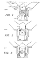
- FIG. 1 is a cross-section representing a dual voice coil loudspeaker 10 with the cone/voice coil assembly 12 at its quiescent center position, where it is seen that voice coils 14 and 16 each have a portion located in a corresponding one of magnetic gaps 18 and 20, polarized as indicated by N and S, and each of these portions is acted upon over the full length of the magnetic gap. While voice coils 14 and 16 each may be offset, as shown, relative to the corresponding magnetic gaps 18 and 20, the two offsets tend to cancel each other so that the coils 14 and 16 function in a complementary manner that provides a large excursion of travel over which the drive force and damping remain relatively constant.
- a short-circuited braking coil 22 having one or more turns is located midway between voice coils 12 and 14, affixed to the voice coil form 24.
- FIG. 2 shows the loudspeaker 10 of FIG. 1 with the voice coil assembly 12 displaced in a first direction (upwardly, as shown) and approaching the limit of the travel range.
- Inductive braking/damping is invoked by braking coil 22 moving into magnetized air gap 18 indicated by dashed flux lines.
- the movement of braking coil 22 relative to the magnetic field induces a current in braking coil 22, and counter-EMF exerts a braking/damping force on the voice coil assembly 12 via braking coil 22, acting to decrease the velocity of (upward) travel and thus limit the excursion smoothly as opposed to abrupt bottoming due to mechanical striking or reaching the limit of the suspension compliance that could occur otherwise.
- FIG. 3 shows the loudspeaker 10 of FIGs. 1 with the voice coil assembly 12, displaced in a second direction (downwardly, as shown), with braking coil 22 moving into magnetized gap 20 and thus invoking the inductive braking/damping action in the same manner as described above in connection with FIG. 2 .
- the present invention provides symmetrical braking/damping in a dual voice coil loudspeaker 10 in combination with a single short-circuited braking coil 22.
- FIG. 4 shows a diaphragm/voice coil assembly 12A of a loudspeaker as in the previous figures but with the ends of the braking coil 22A brought out to a terminal board 26, shown with a jumper 28 connected across the terminals, effectively short-circuiting the braking coil 22A and thus enabling it to function in the same manner as the directly short-circuited braking coil 22 described above in connection with FIGs. 1-3 .
- FIG. 5 shows the diaphragm/voice coil assembly 12A as in FIG. 4 but with the terminals of board 26 connected to a capacitor 30 as an example of a reactive component or network of components that can be thus connected in a circuit loop including the braking coil 22A in order to introduce a frequency-dependent modification to the basic braking effect.
- FIG. 6 shows an actively-enhanced inductive braking system in which the diaphragm/voice coil assembly 12A is configured as in FIG. 4 except that the terminals of board 26 are connected to a feedback driver 32.
- a main amplifier/driver 34 driving the dual voice coils 16 and 18, receives input from an audio source 36.
- Feedback driver is preceded by a special processor 38 which may receive input from audio source 36 an shown or alternatively the input could be obtained at any of several signal nodes in the main amplifier signal path through amplifier/driver 34.
- the frequency and amplitude response of processor 38 can be flexibly modified to provide a feedback current in braking coil 22A that co-operates with induced current in a manner to augment and enhance the braking action in a desired manner.
- the invention could be practiced with the magnetic polarities N and S reversed compared to those shown.
Landscapes
- Physics & Mathematics (AREA)
- Engineering & Computer Science (AREA)
- Acoustics & Sound (AREA)
- Signal Processing (AREA)
- Audible-Bandwidth Dynamoelectric Transducers Other Than Pickups (AREA)
Claims (8)
- Ein bidirektionales induktives Dämpfungssystem in einem elektromagnetischen Audiolautsprecher (10) mit einer dualen Schwingspule, der zweifache Schwingspulen (14, 16) in einer Anordnung mit einer vibrierenden Schwingspule/Membran besitzt, umfassend:einen Rahmen dieses Lautsprechers;einer schwingenden Membrananordnung (12) mit einer zylinderförmigen Schwingspulenform (24);Aufhängungsmittel zum Anbringen dieser Membrananordnung an diesen Rahmen;eine erste Schwingspule (14), die befestigt ist an die Schwingspulenform, die innerhalb eines ersten magnetischen Feldes angeordnet ist, das einen ersten ringförmigen Zwischenraum (18) durchfließt;eine zweite Schwingspule (16), die befestigt ist an der Schwingspulenform und um ein Schwingspulenabstandsmaß von der ersten Schwingspule versetzt ist, wobei die zweite Schwingspule innerhalb eines zweiten magnetischen Feldes angeordnet ist, das einen zweiten ringförmigen Zwischenraum (20) durchfließt, der von dem ersten ringförmigen Zwischenraum um ein Zwischenraumabstandsmaß versetzt ist; undeine kurzgeschlossene Dämpfungsspule (22A), die wenigstens eine Windung umfasst, die an der Schwingspulenform im Wesentlichen in der Mitte befindlich zwischen dieser ersten Schwingspule und dieser zweiten Schwingspule angeordnet ist;wobei die Schwingspulen und die magnetischen Felder relativ dimensioniert und ausgerichtet sind, um zu veranlassen, dass diese Dämpfungsspule, (a) wenn sie sich einer ersten Beschränkung einer Betriebsauslenkung annähert, in ein erstes magnetisches Feld eintritt und deshalb eine Dämpfwirkung auf die Schwingspule/Membrananordnung ausübt, und (b) wenn sie sich einer zweiten Beschränkung einer Betriebsauslenkung annähert, die der ersten Beschränkung entgegengesetzt ist, in ein zweites magnetisches Feld eintritt und deshalb eine Dämpfungswirkung auf die Schwingspule/Membrananordnung ausübt; wobei deshalb diese Dämpfungsspule es ermöglicht Auslenkungen dieser Schwingspulen/Membrananordnung zweiseitig zu beschränken.
- Das bidirektionale induktive Dämpfungssystem nach Anspruch 1, wobei die schwingende zylinderförmige Schwingspulenform innerhalb erster und zweiter Magnetfelder in ersten und zweiten Zwischenraumbereichen zwischen entsprechenden Dauermagnetpolen angeordnet ist, und die kurzgeschlossene Dämpfungsspule an der Schwingspulenform in der Mitte zwischen der ersten Schwingspule und der zweiten Schwingspule angeordnet ist.
- Das bidirektionale induktive Dämpfungssystem nach Anspruch 1, wobei diese kurzgeschlossene Dämpfungsspule eine einzelne Windung umfasst, die als ein Ring konfiguriert ist.
- Das bidirektionale induktive Dämpfungssystem nach Anspruch 1, wobei diese kurzgeschlossene Dämpfungsspule eine Mehrfachwindungsspule umfasst, die zwei Leitungsenden hat, die miteinander verbunden sind, um diese Dämpfungsspule kurzzuschließen.
- Das bidirektionale induktive Dämpfungssystem nach Anspruch 1, wobei
diese Dämpfungsspule konfiguriert und angeordnet ist, um zwei elektrische Enden zu besitzen, und
wobei das Dämpfungssystem weiterhin umfasst:ein Anschlusspaar, das jeweils mit den zwei Enden dieser Dämpfungsspule verbunden ist; undDämpfungsspulenermöglichungsmittel, das zwei Verbindungsstellen besitzt, die mit diesem Anschlusspaar verbunden sind, um eine Schleifenschaltung zu formen, die diese Dämpfungsspule und diese Dämpfungsspulenermöglichungsmittel enthält. - Das bidirektionale induktive Dämpfungssystem nach Anspruch 5, wobei dieses Dämpfungsspulenermöglichungsmittel eine leitende Drahtbrücke (28) umfasst, die über dieses Anschlusspaar verbunden ist um diese Dämpfungsspule kurzzuschließen.
- Das bidirektionale induktive Dämpfungssystem nach Anspruch 5, wobei dieses Dämpfungsspulenermöglichungsmittel wenigstens ein passives, reaktives elektronisches Teil (30) umfasst, in einem Netzwerk, das über dieses Anschlusspaar verbunden ist, um einen induzierten Strom in der Schleife auf eine Weise zu beeinflussen um eine vorbestimmte frequenzabhängige Bremsungs/Dämpfungscharakteristik zu implementieren.
- Das bidirektionale induktive Dämpfungssystem nach Anspruch 5, wobei dieses Dämpfungsspulenermöglichungsmittel einen Rückführungstreiber (32) umfasst, der über dieses Anschlusspaar verbunden ist, und konfiguriert und angeordnet ist, um darauf ein aktives Rückführungssignal anzulegen, das in einem vorbestimmten Verhältnis aus einer Audioquelle (36) abgeleitet ist, um auf einen induzierten Strom in der Dämpfungsspule auf eine vorbestimmte Weise einzuwirken um den Brems/Dämpfungsvorgang dieser Dämpfungsspule zu verbessern.
Applications Claiming Priority (2)
| Application Number | Priority Date | Filing Date | Title |
|---|---|---|---|
| US934642 | 1986-11-25 | ||
| US08/934,642 US5828767A (en) | 1997-09-22 | 1997-09-22 | Inductive braking in a dual coil speaker driver unit |
Publications (3)
| Publication Number | Publication Date |
|---|---|
| EP0903961A2 EP0903961A2 (de) | 1999-03-24 |
| EP0903961A3 EP0903961A3 (de) | 2006-10-18 |
| EP0903961B1 true EP0903961B1 (de) | 2008-11-26 |
Family
ID=25465850
Family Applications (1)
| Application Number | Title | Priority Date | Filing Date |
|---|---|---|---|
| EP98203163A Expired - Lifetime EP0903961B1 (de) | 1997-09-22 | 1998-09-21 | Induktive Bedämpfung in einem Spulenpaarlautsprecherantrieb |
Country Status (6)
| Country | Link |
|---|---|
| US (1) | US5828767A (de) |
| EP (1) | EP0903961B1 (de) |
| JP (1) | JP3133729B2 (de) |
| CA (1) | CA2248433C (de) |
| DE (1) | DE69840252D1 (de) |
| ES (1) | ES2318864T3 (de) |
Families Citing this family (41)
| Publication number | Priority date | Publication date | Assignee | Title |
|---|---|---|---|---|
| JPH11146479A (ja) * | 1997-11-11 | 1999-05-28 | Mitsubishi Electric Corp | スピーカーシステム |
| US6768806B1 (en) * | 1998-03-19 | 2004-07-27 | Harman International Industries, Incorporated | Shorting rings in dual-coil dual-gap loudspeaker drivers |
| JP3984397B2 (ja) * | 1999-09-14 | 2007-10-03 | パイオニア株式会社 | スピーカ |
| AUPQ298299A0 (en) * | 1999-09-20 | 1999-10-14 | Mass Enterprises Pty Ltd | Signal control system |
| AUPQ449999A0 (en) * | 1999-12-07 | 2000-01-06 | Mass Enterprises Pty Ltd | Sound transducer |
| US6694037B1 (en) | 1999-12-10 | 2004-02-17 | Robert Steven Robinson | Spider-less loudspeaker with active restoring apparatus |
| US7050602B2 (en) * | 2000-08-14 | 2006-05-23 | Knowles Electronics Llc. | Low capacitance receiver coil |
| US6639994B1 (en) | 2000-08-16 | 2003-10-28 | Jl Audio, Inc. | Loudspeaker having adjustable motor strength |
| US6774510B1 (en) | 2000-10-25 | 2004-08-10 | Harman International Industries, Inc. | Electromagnetic motor with flux stabilization ring, saturation tips, and radiator |
| JP4098489B2 (ja) * | 2001-05-01 | 2008-06-11 | 並木精密宝石株式会社 | 電磁誘導型アクチュエータを搭載する携帯端末機 |
| CA2408045A1 (en) * | 2001-10-16 | 2003-04-16 | Audio Products International Corp. | Loudspeaker with large displacement motional feedback |
| JP4385981B2 (ja) * | 2005-03-30 | 2009-12-16 | オンキヨー株式会社 | 動電型スピーカー |
| EP1999993A4 (de) * | 2006-03-06 | 2011-03-30 | Gen Innovations Inc | Positionell sequenziertes lautsprechersystem |
| US20070297639A1 (en) * | 2006-06-21 | 2007-12-27 | Noll Michael A | Multiple magnet loudspeaker |
| US8385580B2 (en) | 2006-08-31 | 2013-02-26 | Adamson Systems Engineering Inc. | High power low frequency transducers and method of assembly |
| JP5332146B2 (ja) * | 2007-07-26 | 2013-11-06 | ヤマハ株式会社 | スピーカ装置 |
| JP5034845B2 (ja) * | 2007-10-02 | 2012-09-26 | ヤマハ株式会社 | スピーカユニットおよびスピーカ装置 |
| JP2009194467A (ja) * | 2008-02-12 | 2009-08-27 | Victor Co Of Japan Ltd | ボイスコイル及びスピーカ |
| FR2961053B1 (fr) * | 2010-06-04 | 2013-04-12 | Focal Jmlab | Haut-parleur acoustique |
| CN102378083A (zh) * | 2010-08-12 | 2012-03-14 | 郭建文 | 动态阻尼中、低音扬声器 |
| JP2014504108A (ja) * | 2010-12-23 | 2014-02-13 | ニーデルマン,ポール | 薄型スピーカー |
| US8781150B2 (en) | 2011-02-14 | 2014-07-15 | Robert Bosch Gmbh | Multiple magnetic air gap motor |
| US9571926B2 (en) * | 2011-04-08 | 2017-02-14 | Christopher Technology (Shanghai) Limited | High-efficiency low-voltage-power-supply high-power-output audio driver architecture |
| GB2499026B (en) * | 2012-02-03 | 2014-05-28 | Canon Kk | A loudspeaker driver with sensing coils for sensing the position and velocity of a voice-coil |
| US8855356B1 (en) | 2012-12-18 | 2014-10-07 | Skullcandy, Inc. | Dual ring magnet apparatus |
| US9838794B2 (en) * | 2013-04-26 | 2017-12-05 | Sound Solutions International Co., Ltd. | Double coil speaker |
| US9173035B2 (en) | 2013-11-07 | 2015-10-27 | Harman International Industries, Incorporated | Dual coil moving magnet transducer |
| US9445201B2 (en) * | 2013-11-21 | 2016-09-13 | Harman International Industries, Inc. | Inverted dual coil transducer |
| US9374052B1 (en) * | 2014-11-27 | 2016-06-21 | Blackberry Limited | Voice coil protection using damping |
| US9872109B2 (en) | 2014-12-17 | 2018-01-16 | Knowles Electronics, Llc | Shared coil receiver |
| US9854365B2 (en) | 2016-04-15 | 2017-12-26 | Harman International Industries, Inc. | Loudspeaker motor and suspension system |
| DE102018002290A1 (de) | 2017-03-27 | 2018-09-27 | Sound Solutions International Co., Ltd. | System und Verfahren zum Anlegen eines Tonsignals an einen elektrodynamischen Akustikwandler mit mehreren Spulen |
| US10295011B2 (en) * | 2017-10-06 | 2019-05-21 | The Boeing Company | Systems and tuned magnetic dashpots for using inductor(s) in magnetic skyhook damper isolation |
| KR20220002951A (ko) | 2019-04-11 | 2022-01-07 | 메이츠 홀딩 비.브이. | 선형 모터 자석 조립체 및 라우드스피커 유닛 |
| GB201907610D0 (en) * | 2019-05-29 | 2019-07-10 | Pss Belgium Nv | Loudspeaker |
| US11948549B2 (en) | 2019-07-17 | 2024-04-02 | Sound Solutions International Co., Ltd. | Electromagnetic actuator for a display with improved spring arrangement and output device with said actuator |
| GB2586528B (en) * | 2019-08-23 | 2021-09-22 | Tymphany Acoustic Tech Huizhou Co Ltd | A method and system for driving a voice coil of a loudspeaker |
| US11678123B2 (en) | 2020-05-20 | 2023-06-13 | Sound Solutions International Co., Ltd. | Electromagnetic actuator for a speaker or a sound transducer with a high-strength metal connection between the voice coil and the magnet system |
| CN113727258B (zh) | 2020-05-20 | 2024-01-26 | 奥音科技(镇江)有限公司 | 电动激励器、扬声器、电动换能器和输出设备 |
| US12439209B2 (en) | 2022-06-10 | 2025-10-07 | Sound Solutions International (Zhenjiang) Co., Ltd. | Speaker with improved frequency response and related electronic sound signal circuit, sound system and production method |
| JP2024080123A (ja) | 2022-12-01 | 2024-06-13 | アルプスアルパイン株式会社 | スピーカ |
Family Cites Families (7)
| Publication number | Priority date | Publication date | Assignee | Title |
|---|---|---|---|---|
| US3047661A (en) * | 1957-01-18 | 1962-07-31 | Daniel E Winker | High fidelity audio system |
| JPS5476132A (en) * | 1977-11-30 | 1979-06-18 | Hitachi Ltd | Electro-dynamic type speaker |
| DE4041858A1 (de) * | 1990-12-24 | 1992-07-02 | Nokia Unterhaltungselektronik | Antriebssystem fuer langhubige tieftonlautsprecher |
| DE4317775C2 (de) * | 1993-02-03 | 1995-02-02 | Foster Electric Co Ltd | Lautsprecher |
| JPH0715794A (ja) * | 1993-06-21 | 1995-01-17 | Matsushita Electric Ind Co Ltd | スピーカ |
| JP3161677B2 (ja) * | 1995-02-17 | 2001-04-25 | アルパイン株式会社 | スピーカ |
| JP2002283585A (ja) * | 2001-03-26 | 2002-10-03 | Fuji Xerox Co Ltd | インクジェット記録ヘッド |
-
1997
- 1997-09-22 US US08/934,642 patent/US5828767A/en not_active Expired - Lifetime
-
1998
- 1998-09-21 EP EP98203163A patent/EP0903961B1/de not_active Expired - Lifetime
- 1998-09-21 DE DE69840252T patent/DE69840252D1/de not_active Expired - Lifetime
- 1998-09-21 ES ES98203163T patent/ES2318864T3/es not_active Expired - Lifetime
- 1998-09-22 JP JP10268052A patent/JP3133729B2/ja not_active Expired - Fee Related
- 1998-09-22 CA CA002248433A patent/CA2248433C/en not_active Expired - Fee Related
Also Published As
| Publication number | Publication date |
|---|---|
| EP0903961A3 (de) | 2006-10-18 |
| US5828767A (en) | 1998-10-27 |
| JPH11164394A (ja) | 1999-06-18 |
| ES2318864T3 (es) | 2009-05-01 |
| CA2248433C (en) | 2000-05-09 |
| DE69840252D1 (de) | 2009-01-08 |
| CA2248433A1 (en) | 1999-03-22 |
| JP3133729B2 (ja) | 2001-02-13 |
| EP0903961A2 (de) | 1999-03-24 |
Similar Documents
| Publication | Publication Date | Title |
|---|---|---|
| EP0903961B1 (de) | Induktive Bedämpfung in einem Spulenpaarlautsprecherantrieb | |
| US4783824A (en) | Speaker unit having two voice coils wound around a common coil bobbin | |
| US4550430A (en) | Sound reproducing system utilizing motional feedback and an improved integrated magnetic structure | |
| US4598178A (en) | Means for critically damping a dynamic loudspeaker | |
| JPH01272298A (ja) | 駆動装置 | |
| WO1994016536A1 (en) | Speaker containing dual coil | |
| EP1617704B1 (de) | Empfänger mit mehreren Antriebsspulen | |
| US5373563A (en) | Self damping speaker matching device | |
| US7873180B2 (en) | Voice coil actuator | |
| EP0409429A2 (de) | Lautsprecher-Betreibereinheit | |
| JP3365958B2 (ja) | スピーカ | |
| GB2473921A (en) | Compensation of rising frequency response in passive current-driven loudspeakers | |
| WO1999030533A1 (en) | Electrodynamic acoustic transducer with reduced equivalent inductance of the moving parts | |
| JPH067711B2 (ja) | スピ−カ | |
| US2494918A (en) | Inductively energized electro-dynamic loud-speaker | |
| JP3128022B2 (ja) | 同軸スピーカ | |
| US4461933A (en) | Electrical/mechanical transducers | |
| JP3991792B2 (ja) | スピーカ | |
| CA2192163C (en) | Self-damping speaker matching device and method | |
| KR200284571Y1 (ko) | 자화필름을 이용한 고정형 코일구조를 갖는단방향/양방향 전기-음향 변환기 | |
| KR20030083774A (ko) | 자화필름을 이용한 고정형 코일구조를 갖는 단방향/양방향전기-음향 변환기 및 전기-음향 변환 방법 | |
| JPH04364000A (ja) | 動電形スピーカ | |
| Watkins | Circumventing Efficiency and Bass Extension Limitations | |
| JP2546339Y2 (ja) | スピーカ | |
| JPS5912700A (ja) | 複合型スピ−カ |
Legal Events
| Date | Code | Title | Description |
|---|---|---|---|
| PUAI | Public reference made under article 153(3) epc to a published international application that has entered the european phase |
Free format text: ORIGINAL CODE: 0009012 |
|
| AK | Designated contracting states |
Kind code of ref document: A2 Designated state(s): AT BE CH CY DE DK ES FI FR GB GR IE IT LI LU MC NL PT SE |
|
| AX | Request for extension of the european patent |
Free format text: AL;LT;LV;MK;RO;SI |
|
| PUAL | Search report despatched |
Free format text: ORIGINAL CODE: 0009013 |
|
| AK | Designated contracting states |
Kind code of ref document: A3 Designated state(s): AT BE CH CY DE DK ES FI FR GB GR IE IT LI LU MC NL PT SE |
|
| AX | Request for extension of the european patent |
Extension state: AL LT LV MK RO SI |
|
| 17P | Request for examination filed |
Effective date: 20070330 |
|
| AKX | Designation fees paid |
Designated state(s): DE ES GB IT |
|
| 17Q | First examination report despatched |
Effective date: 20070704 |
|
| GRAP | Despatch of communication of intention to grant a patent |
Free format text: ORIGINAL CODE: EPIDOSNIGR1 |
|
| GRAS | Grant fee paid |
Free format text: ORIGINAL CODE: EPIDOSNIGR3 |
|
| GRAA | (expected) grant |
Free format text: ORIGINAL CODE: 0009210 |
|
| AK | Designated contracting states |
Kind code of ref document: B1 Designated state(s): DE ES GB IT |
|
| REG | Reference to a national code |
Ref country code: GB Ref legal event code: FG4D |
|
| REF | Corresponds to: |
Ref document number: 69840252 Country of ref document: DE Date of ref document: 20090108 Kind code of ref document: P |
|
| REG | Reference to a national code |
Ref country code: ES Ref legal event code: FG2A Ref document number: 2318864 Country of ref document: ES Kind code of ref document: T3 |
|
| PLBE | No opposition filed within time limit |
Free format text: ORIGINAL CODE: 0009261 |
|
| STAA | Information on the status of an ep patent application or granted ep patent |
Free format text: STATUS: NO OPPOSITION FILED WITHIN TIME LIMIT |
|
| 26N | No opposition filed |
Effective date: 20090827 |
|
| PG25 | Lapsed in a contracting state [announced via postgrant information from national office to epo] |
Ref country code: IT Free format text: LAPSE BECAUSE OF NON-PAYMENT OF DUE FEES Effective date: 20090921 |
|
| PGFP | Annual fee paid to national office [announced via postgrant information from national office to epo] |
Ref country code: DE Payment date: 20130927 Year of fee payment: 16 Ref country code: ES Payment date: 20130926 Year of fee payment: 16 |
|
| REG | Reference to a national code |
Ref country code: DE Ref legal event code: R119 Ref document number: 69840252 Country of ref document: DE |
|
| PG25 | Lapsed in a contracting state [announced via postgrant information from national office to epo] |
Ref country code: DE Free format text: LAPSE BECAUSE OF NON-PAYMENT OF DUE FEES Effective date: 20150401 |
|
| REG | Reference to a national code |
Ref country code: ES Ref legal event code: FD2A Effective date: 20151027 |
|
| PG25 | Lapsed in a contracting state [announced via postgrant information from national office to epo] |
Ref country code: ES Free format text: LAPSE BECAUSE OF NON-PAYMENT OF DUE FEES Effective date: 20140922 |
|
| PGFP | Annual fee paid to national office [announced via postgrant information from national office to epo] |
Ref country code: GB Payment date: 20170821 Year of fee payment: 20 |
|
| REG | Reference to a national code |
Ref country code: GB Ref legal event code: PE20 Expiry date: 20180920 |
|
| PG25 | Lapsed in a contracting state [announced via postgrant information from national office to epo] |
Ref country code: GB Free format text: LAPSE BECAUSE OF EXPIRATION OF PROTECTION Effective date: 20180920 |