EP0903659B1 - Dispositif de commande pour une console de jeux - Google Patents
Dispositif de commande pour une console de jeux Download PDFInfo
- Publication number
- EP0903659B1 EP0903659B1 EP98117834A EP98117834A EP0903659B1 EP 0903659 B1 EP0903659 B1 EP 0903659B1 EP 98117834 A EP98117834 A EP 98117834A EP 98117834 A EP98117834 A EP 98117834A EP 0903659 B1 EP0903659 B1 EP 0903659B1
- Authority
- EP
- European Patent Office
- Prior art keywords
- actuating
- actuators
- thrusting
- main body
- body unit
- Prior art date
- Legal status (The legal status is an assumption and is not a legal conclusion. Google has not performed a legal analysis and makes no representation as to the accuracy of the status listed.)
- Expired - Lifetime
Links
Images

Classifications
-
- G—PHYSICS
- G06—COMPUTING; CALCULATING OR COUNTING
- G06F—ELECTRIC DIGITAL DATA PROCESSING
- G06F3/00—Input arrangements for transferring data to be processed into a form capable of being handled by the computer; Output arrangements for transferring data from processing unit to output unit, e.g. interface arrangements
- G06F3/01—Input arrangements or combined input and output arrangements for interaction between user and computer
- G06F3/02—Input arrangements using manually operated switches, e.g. using keyboards or dials
- G06F3/0202—Constructional details or processes of manufacture of the input device
- G06F3/0216—Arrangements for ergonomically adjusting the disposition of keys of a keyboard
-
- A—HUMAN NECESSITIES
- A63—SPORTS; GAMES; AMUSEMENTS
- A63F—CARD, BOARD, OR ROULETTE GAMES; INDOOR GAMES USING SMALL MOVING PLAYING BODIES; VIDEO GAMES; GAMES NOT OTHERWISE PROVIDED FOR
- A63F13/00—Video games, i.e. games using an electronically generated display having two or more dimensions
- A63F13/20—Input arrangements for video game devices
- A63F13/24—Constructional details thereof, e.g. game controllers with detachable joystick handles
-
- A—HUMAN NECESSITIES
- A63—SPORTS; GAMES; AMUSEMENTS
- A63F—CARD, BOARD, OR ROULETTE GAMES; INDOOR GAMES USING SMALL MOVING PLAYING BODIES; VIDEO GAMES; GAMES NOT OTHERWISE PROVIDED FOR
- A63F13/00—Video games, i.e. games using an electronically generated display having two or more dimensions
- A63F13/25—Output arrangements for video game devices
- A63F13/28—Output arrangements for video game devices responding to control signals received from the game device for affecting ambient conditions, e.g. for vibrating players' seats, activating scent dispensers or affecting temperature or light
- A63F13/285—Generating tactile feedback signals via the game input device, e.g. force feedback
-
- A—HUMAN NECESSITIES
- A63—SPORTS; GAMES; AMUSEMENTS
- A63F—CARD, BOARD, OR ROULETTE GAMES; INDOOR GAMES USING SMALL MOVING PLAYING BODIES; VIDEO GAMES; GAMES NOT OTHERWISE PROVIDED FOR
- A63F2300/00—Features of games using an electronically generated display having two or more dimensions, e.g. on a television screen, showing representations related to the game
- A63F2300/10—Features of games using an electronically generated display having two or more dimensions, e.g. on a television screen, showing representations related to the game characterized by input arrangements for converting player-generated signals into game device control signals
- A63F2300/1037—Features of games using an electronically generated display having two or more dimensions, e.g. on a television screen, showing representations related to the game characterized by input arrangements for converting player-generated signals into game device control signals being specially adapted for converting control signals received from the game device into a haptic signal, e.g. using force feedback
-
- A—HUMAN NECESSITIES
- A63—SPORTS; GAMES; AMUSEMENTS
- A63F—CARD, BOARD, OR ROULETTE GAMES; INDOOR GAMES USING SMALL MOVING PLAYING BODIES; VIDEO GAMES; GAMES NOT OTHERWISE PROVIDED FOR
- A63F2300/00—Features of games using an electronically generated display having two or more dimensions, e.g. on a television screen, showing representations related to the game
- A63F2300/10—Features of games using an electronically generated display having two or more dimensions, e.g. on a television screen, showing representations related to the game characterized by input arrangements for converting player-generated signals into game device control signals
- A63F2300/1043—Features of games using an electronically generated display having two or more dimensions, e.g. on a television screen, showing representations related to the game characterized by input arrangements for converting player-generated signals into game device control signals being characterized by constructional details
-
- A—HUMAN NECESSITIES
- A63—SPORTS; GAMES; AMUSEMENTS
- A63F—CARD, BOARD, OR ROULETTE GAMES; INDOOR GAMES USING SMALL MOVING PLAYING BODIES; VIDEO GAMES; GAMES NOT OTHERWISE PROVIDED FOR
- A63F2300/00—Features of games using an electronically generated display having two or more dimensions, e.g. on a television screen, showing representations related to the game
- A63F2300/30—Features of games using an electronically generated display having two or more dimensions, e.g. on a television screen, showing representations related to the game characterized by output arrangements for receiving control signals generated by the game device
- A63F2300/302—Features of games using an electronically generated display having two or more dimensions, e.g. on a television screen, showing representations related to the game characterized by output arrangements for receiving control signals generated by the game device specially adapted for receiving control signals not targeted to a display device or game input means, e.g. vibrating driver's seat, scent dispenser
Definitions
- This invention relates to an actuating device used in a game machine employing a display unit of, for example, a television receiver. More particularly, it relates to an actuating device for a game machine having an actuating portion for controlling various operations, such as those of rotating a display character on a display screen, continuously changing the movement speed or deforming the display character.
- a game machine employing a television receiver has a main body unit of the game machine, connected to a television receiver used as a display device, and an actuating device for controlling a display character connected via a connection cable to the main body unit of the game machine and which is displayed on the display screen of the television receiver.
- the main body unit of the game machine has, enclosed therein, a disc driving portion for reproducing an optical disc as a recording medium carrying a game program and a picture processing device for displaying on the screen of the television receiver a display character along with the background picture in accordance with a game program recorded on the optical disc.
- the actuating device On the actuating device, connected o the main body unit of the game machine, there are arranged plural actuators. The user actuates these actuators to input the command information concerning the operation of the display characters displayed on the display screen of the television receiver to control the movement direction of the display character depending on the command information.
- the actuating device used in this type of the game machine is held by hand or finger during use.
- a direction command actuating unit having a cross-shaped or circular direction indicating operating button and a function setting executing unit having plural function setting executing buttons for setting the operating function of the display character or executing its operation.
- the direction command actuating unit includes four switches having actuators which are arranged orthogonally relative to one another and which are brought into and out of contact with the contact. These switches are selectively turned on and off by the cross-shaped or circular direction command actuators for moving the display character. For example, the display character is digitally moved in the direction along which is arrayed the one of the four switches that is turned on.
- the function setting executing unit includes switches in association with the plural function setting actuators so that the function of the display character allocated to each button is set or the function proper to the display character is executed.
- the direction command actuator of the actuating device is configured so that the one of the four switches arranged in the mutually perpendicular directions gives a command signal of moving the display character in the direction along which is arrayed the switch turned on, so that it is not possible to give the command information of rotating and simultaneously advancing the display character or changing its line of sight.
- the result is that it becomes difficult to construct the game program employing the display character performing diversified operations.
- an actuator adapted to be thrust and simultaneously rotated in the actuating unit adapted for rotating a display character or changing its configuration.
- This type of the actuator is gripped or thrust by hand or finger.
- the actuator for actuating the direction command actuator is also thrust by being thrust by hand or finger.
- the actuator of the actuating device for the game machine is frequently acted on during execution of the game program. Moreover, the actuating unit is used for prolonged time.
- the document US-A-5643087 discloses an input device for an interactive computer simulation or game which includes a structure having at least two degrees-of-freedom which is moveable by a digit of a user to transmit input signal to a computer. At least one actuator connected to the moveable structure receives inputs from a computer and applies forces in the at least two degrees-of-freedom to the moveable structure and thereby to the digit of the user.
- This known device comprises only one moveable structure including a digit cradle and some conventional input switches on a main body.
- the document EP-A-0 695 566 shows a manipulator including a housing which consists of right and left handles and a coupling for coupling them.
- the both handles are formed with grips and direction instructing switches for instructing the character moving direction.
- Each of the direction instructing switches comprises, for example, a cross key top capable of instructing four orthogonal directions, and further comprises four pressing pads corresponding to the four directions.
- an actuating device for a game machine includes first and second grips protruded from one side of each end of the main body unit of the device. On one and the opposite ends of the main body unit are provided first and second actuating units. Each of the first and second actuating units is provided with plural thrusting actuators projected to the upper surface side of the main body unit and a plurality of signal input elements thrust by said thrusting actuators.
- the actuating device also includes third and fourth actuating units arranged facing each other on the proximal ends of said first and second grips said third and fourth actuators being provided with a rotation actuator rotable through 360 degrees about an actuating shaft as center and a signal inputting element actuated by this rotation actuator, said rotation actuators each having a main actuator body portion of synthetic resin and a top layer of a flexible material being integrally formed with said main actuator body portion on its upper surface side
- These third and fourth actuating units can be actuated by thumb fingers of both hands of the user holding the first and second grips.
- the third and fourth actuating units including the signal input terminals actuated by the rotation actuators input to the main body unit of the device command signals enabling rotation and translation simultaneously of the display character displayed on the screen, movement of the display character with varying speed or change of the configuration.
- each rotation actuator includes a main actuator body portion of a synthetic resin connected to an associated actuating unit and a top portion of a flexible material swollen-out at its distal end and which is formed as-one with the main actuator body portion. Since the top portion contacted with the hand or finger has its distal end swollen-out and is formed of a flexible material, an optimum contact feeling can be realized to improve use feeling.
- a vibration-imparting unit which imparts vibrations to the user during operation to execute a game with a vivid play feeling.
- This vibration-imparting unit is provided in the first and second grips and is made up of a driving motor and an eccentric member mounted on a driving shaft of the motor.
- the vibration-imparting unit has different vibration-imparting states to realize a more vivid play feeling in executing a game.
- the top portion of the rotation actuator for entering a command signal in executing the game program, contacted by the hand or finger of the user is formed of a flexible material and is swollen out at its distal lend, optimum contact feeling may be realized to improve the use feeling.
- the main actuator body portion and the top portion making up the rotation actuator is formed by two-color molding, the main actuator body portion and the top portion can be positively unified to each other to assure high operational reliability of the actuating unit.
- the actuating device for the game machine is connected to a main body unit of the game machine having enclosed therein a disc driving unit for reproducing an optical disc as a recording medium carrying a recorded game program and a picture processing device for displaying a display character along with the background on a screen of the television receiver in accordance with a game program recorded on the optical disc.
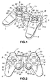
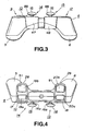
- An actuating device 1 for the game machine includes a main body unit 4 made up of an upper half 2 and a lower half 3 abutted and connected to each other by fasteners, such as set screws, as shown in Fig.1. From one side of ends of the main body unit 4 are protruded a first grip 5 and a second grip 6 which are held by left and right palms when the device 1 is connected to the main body unit of the game machine for executing the game. There first and second grips 5, 6 are protruded towards the lower side of the main body unit 4 as they are flared and spaced apart from each other towards their distal ends, as shown in Figs.2 to 4.
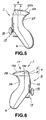
- these grips are tapered from the connecting sides to the main body unit 4 towards the distal ends, while being arcuately contoured in peripheral surfaces and at the distal ends, as shown in Figs.2, 5 and 6.
- first actuating unit 9 On one end of the main body unit 4 is provided a first actuating unit 9, having first to fourth thrusting actuators 8a, 8b, 8c, 8d protruded on the upper surface side of the main body unit 4, as shown in Figs. 1 and 2.
- the first to fourth thrusting actuators 8a to 8d making up the first actuating unit 9 are formed as-one with a rotary actuating member 10 having its center portion supported for rotation and are arrayed in mutually perpendicular directions about the center of rotation of the rotary actuating member 10. That is, the first actuating unit 9 is provided with switch elements as signal inputting elements in association with the first to fourth thrusting actuators 8a to 8d.
- the first actuating unit 9 By selectively thrusting the first to fourth thrusting actuators 8a to 8d to turn the switches associated with these thrusting actuators 8a to 8d on and off, the display character is moved in the arraying direction of the thrustingly actuated thrusting actuators 8a to 8d.
- a second actuating unit 12 having first to fourth thrusting actuators 11a, 11b, 11c, 11d protruded from the main body unit 4 and which are arranged in mutually perpendicular directions, as shown in Figs.1 and 2.
- These first to fourth thrusting actuators 11a to 11d are formed as independent members and signal inputting elements, not shown, are provided in association with the thrusting actuators 11a to 11d.
- the second actuating unit 12 operates as a function setting executing unit for setting the functions of the display character allocated to the thrusting actuators 11a to 11d or executing the functions owned by the display character by turning the switches associated with the first to fourth thrusting actuators 11 a to 11d on and off.
- the actuating device 1 includes third and fourth actuators 14, 15 mounted facing each other on the corners of the proximal ends of the first and second grips 5, 6 connecting to the main body unit 4, as shown in Figs. 1 and 2.
- These third and fourth actuators 14, 15 are provided with a rotation actuator 16 rotatable through 360° about an actuating shaft as center and a signal inputting element, such as a variable resistance element, actuated by this rotation actuator 16.
- the rotation actuator 16 is mounted at the distal end of an actuating shaft, mounted under the bias of a biasing member for restoration thereof to a neutral position, and is rotated through 360° about the center of rotation of the actuating shaft as the center of rotation.
- These third and fourth actuators 14, 15 are used an actuating unit which, by rotating the rotation actuator 16, issues a command signal for realizing analog movements, such as rotating and simultaneously moving the display character, moving the display character with a variable speed, or varying its configurations.
- fifth and sixth actuating units 17, 18 are provided with first and second thrusting actuators 19a, 19b and 20a, 20b, respectively, as shown in Fig.4. These thrusting actuators 19a, 19b and 20a, 20b are provided with associated switching elements.
- the fifth and sixth actuating units 17, 18 operate as function setting executing units for setting the functions of the display character allocated to the thrusting actuators 19a, 19b and 20a, 20b or executing the functions owned by the display character by turning on switches, not shown, associated with the first and second thrusting actuators 19a, 19b and 20a, 20b.
- a start switch 22 for commanding the start of a game
- a selection switch 23 for selecting relative facility or difficulty when starting a game, as shown in Figs. 1 and 2.
- a mode selection switch 24 for selecting the operating mode of the third and fourth actuating units 14, 15
- a display unit 25 for displaying the state of the operating modes of the third and fourth actuating units 14, 15.
- the display unit 25 is constituted by a light emitting element, such as LED.
- an operating mode enabling the inputting of a command signal from the third and fourth actuating units 14, 15 or an operating mode inhibiting the inputting of the command signal from the third and fourth actuating units 14, 15 is selected, while the command signal from the third and fourth actuating units 14, 15 is enabled to be entered and the operating mode is selected which has made a switching between the function of the first to fourth thrusting actuators 11a to 11d of the second actuating unit 12 and the function of the first and second thrusting actuators 19a, 19b and 20a, 20b of the fifth and sixth actuating units 17, 18.
- the display unit 25 is turned on and off depending on the state of these operating modes, while switching is made of the display light.
- engagement recesses 26, 27 On the lower side of the main body unit 4 are formed engagement recesses 26, 27 in which portions of hands or fingers Rf, Lf are engaged when the first grip 5 and the second grip 6 are gripped by the hands or fingers Rf, Lf, as shown in Figs.5 to 8.
- These engagement recesses 26, 27 are formed as smoothly curved reentrant recesses, as shown in Figs.5 and 6.
- finger supports 28, 29, On the front side of the main body unit 4 are formed depending finger supports 28, 29, in association with the engagement recesses 26, 27, as shown in Figs.5 and 6. Specifically, these finger supports 28, 29 are protuberantly formed from the lower ends of protrusions 31, 32 on both ends on the front surface of the main body unit 4 where the fifth and sixth actuating units 17, 18 are formed.
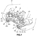
- the first and second grips 5, 6 are protuberantly provided on the main body unit 4, as described above, these first and second grips 5, 6 are held in a wrapping fashion by both palms of the hands, as shown in Fig.7, so that there is no necessity of holding the main body unit 4 by fingers, such that the actuating device 1 an be held in a state in which up to a maximum of ten and at least six fingers can be moved freely.
- thumb fingers Rf1, Lf1 of both hands can be extended over the rotation actuators 16 of the third and fourth actuating units 14, 15, over the first to fourth thrusting actuators 8a to 8d of the first actuating unit 9 and over the first to fourth thrusting actuators 11a to 11d of the second actuating unit 12 to permit selective thrusting of the rotation actuators 16 and the thrusting actuators 8a to 8d and 11a to 11d.
- the rotation actuators 16 of the third and fourth actuating units 14, 15 are arranged facing each other on the proximal ends of the first and second grips 5, 6 corresponding to the connecting portions to the main body unit 4, the rotation actuators 16 are closest to the thumb fingers Rf1, Lf1 ofboth hands when the first and second grips 5, 6 are gripped by the hands, so that the rotation actuators 16 can be easily rotated by both thumb fingers Rf1, Lf1.
- index fingers Rf2, Lf2 and middle fingers Rf3, Lf3 of both hands can be extended to such positions as to enable selective thrusting of the first and second thrusting actuators 19a, 19b, 20a, 20b of the fifth and sixth actuating units 17, 18.
- finger supports 28, 29 can be held as the first and second grips 5, 6 are wrapped in the palms of the hands, while fourth fingers Rf4, Lf4 of both hands and/or little fingers Rf5, Lf5 are engaged in the engagement recesses 26, 27, so that the main body unit 4 can be held at fixed positions relative to the fingers of the hands of the user. That is, the fingers can be correctly positioned in association with the first to sixth actuating units 9, 12, 14, 15, 17 and 18, thus realizing reliable actuation.
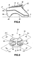
- the actuating device 1 can also be set on a planar setting surface S, such as a table, as shown in Fig.8. If the actuating device 1 is set on the setting surface S, with the distal ends of the first and second grips 5, 6 and those of the finger supports 28, 29 as supports, the actuating surfaces of the first to fourth thrusting actuators 8a to 8d of the first actuating unit 9, the first to fourth thrusting actuators 11a to 11d of the second actuating unit 12 and the rotation actuators 16 of the third and fourth actuating units 14, 15 are substantially parallel to the setting surface S, as shown in Fig.8.
- the actuating device 1 of the present invention can be set on the planar setting surface S and the hands placed on the setting surface S, with the first and second grips 5, 6 being supported by the palms to actuate the first to sixth actuating units 9, 12, 14, 15, 17 and 18.
- the first actuating unit 9 of the actuating device 1 is explained in further detail.
- the first to fourth thrusting actuators 8a to 8d are protuberantly formed on the rotary actuating member 10 within the substantially cross-shaped recess 30 on one end side on the upper surface of the main body unit 4.
- On the upper and lower and left and right ends of the cross-shaped recess 30 are provided direction indicators 31a, 31b, 31c, 31d towards the inner sides of which four apertures 32 are formed in mutually perpendicular directions for allowing the first to fourth thrusting actuators 8a to 8d to be protruded from the upper surface side of the main body unit 4, respectively.
- the center area surrounded by these apertures 32 is formed as a central supporting projection 33 for supporting the center portion on the upper surface side of the main body unit 4, as shown in Fig. 10.
- This central supporting projection 33 is formed as-one with the upper inner surface of the main body unit 4.
- the central supporting projection 33 is faced by an elastic member 35 having four movable contacts 34 thrust by the first to fourth thrusting actuators 8a to 8d.
- a spherically-shaped fulcrum member 36 such as a steel ball, adapted for supporting the center on the low surface side of the rotary actuating member 10.
- the elastic member 35 is faced by a circuit substrate 38 including four stationary contacts 37 adapted for being contacted with and disengaged from the movable contacts 34.
- the rotary actuating member 10 constituting the first actuating unit 9 is made up of a circular-shaped base 39, first to fourth thrusting actuators 8a to 8d formed as-one with the upper part of the base 39, a spherically-shaped first recess 41 in the lower surface of the center portion of the base 39, adapted for engaging in the spherical surface of a spherically-shaped fulcrum member 36, a spherically-shaped second recess 42 in the upper center surface portion of the base 39 adapted for engaging with the central supporting projection 33 and a contact guide 43 protuberantly formed on the lower side of the base 39 for thrusting the back surface of the movable contacts 34 of the elastic member 35, as shown in Figs.9 and 10.
- the four first to fourth thrusting actuators 8a to 8d formed as-one with the rotary actuating member 10, are formed on the upper side of the base 39 so that the thrusting actuators 8a to 8d are tapered in a direction towards an imaginary converging point and so that the thrusting actuators 8a to 8d are increased in thickness in a direction from the center towards the outer ends, as shown in Fig.9.
- the thrusting actuators 8a to 8d are protruded via apertures 32 from the upper surface of the main body unit 4, as shown in Fig.9.
- the elastic member 35 is sandwiched between a circuit substrate 38 and the rotary actuating member 10 and is provided with a number of movable contacts 34, such as ruber contacts, corresponding to the number of the first to fourth thrusting actuators 8a to 8d.
- a fulcrum member 36 is spherically-shaped and is arranged at a mid portion of the rotary actuating member 10 in register with the central supporting projection 33.
- the fulcrum member 36 is engaged in a first recess 41 formed at the center of the rotary actuating member 10.
- the first to fourth thrusting actuators 8a to 8d are arranged radially, about the central supporting projection 33 as center, and are progressively increased in height from the imaginary converging side ends towards the opposite outer ends.
- the relative position can be easily discriminated by the tactile feeling at the end of the finger, due to the step difference between the center portion and the first to fourth thrusting actuators 8a to 8d, such that, when the finger end is shifted for switch actuation from the center towards the outer side of the recess 30, which of the first to fourth thrusting actuators 8a to 8d is being thrust can be easily discriminated based solely on the tactile feeling.
- the rotary actuating member 10, formed as-one with the first to fourth thrusting actuators 8a to 8d, are formed by molding a synthetic resin material of a relatively high toughness. The result is that the first to fourth thrusting actuators 8a to 8d of increased toughness are thrust by the hand or finger such that the operational feeling is not optimum.
- a top layer 7 formed of a soft flexible material is formed as-one with the upper surfaces of the first to fourth thrusting actuators 8a to 8d acted on by the hand or finger, as shown in Figs. 10 and 11.
- the top layer 7 is formed of a material exhibiting rubber-like elasticity.
- the top layer 7 is molded in two colors and formed as-one with the first to fourth thrusting actuators 8a to 8d.
- the top layer 7 is slightly swollen out at the mid portion for improving the tactile feeling.
- the top layer 7 of a soft flexible material is provided on the first to fourth thrusting actuators 8a to 8d, it is possible to relieve the impact otherwise applied to the hand or finger on thrusting actuation thus improving the operational feeling on actuation with the hand or finger. Since the elastomer of the top layer 7 has large friction, it operates for inhibiting the slip of the hand or finger on thrusting actuation of the first to fourth thrusting actuators 8a to 8d.
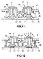
- the rotary actuating member 10 is uplifted by the contact guide 43, under the bias of the elastic member 35, as shown in Fig.11, with the central supporting projection 33 engaging in the spherically-shaped second recess 42 of the rotary actuating member 10. Simultaneously, the peripheral end of the circular-shaped base 39 is retained by the end of the aperture 32, the rotary actuating member 10 being then retained in an initial position, with the first to fourth thrusting actuators 8a to 8d being projected to outside or on the upper surface side of the main body unit 4.
- the third thrusting actuators 8c is thrust in the direction indicated by arrow A or B in Fig.12, the rotary actuating member 10 is rotated in the direction indicated by arrow R1 or towards right in Fig. 12.
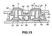
- the third thrusting actuators 8c thrusts the elastic member 35 downwards. If the third thrusting actuators 8c is thrust further, the rotary actuating member 10 is rotated in the direction indicated by arrow R1 in Fig. 13, about the fulcrum member 36 as the center of rotation, until the movable contacts 34 are contacted with the stationary contacts 37 to establish the electrical connection.
- the third thrusting actuator 8c is rotated in the direction indicated by arrow R2 in Fig. 13 to separate the movable contacts 34 from the stationary contacts 37. If the third thrusting actuator 8c is rotated further in the direction indicated by arrow R2 in Fig. 13 until the central supporting projection 33 is engaged in the second recess 42, the rotary actuating member 10 is reset to the initial position shown in Fig.11.
- the elastic member 35 is deformed against the force of elasticity.
- the first thrusting actuators 8a is moved in the direction indicated by arrow C in Fig. 10, as the first recess 41 is rotated on the spherical surface of the fulcrum member 36, so that the movable contacts 34 are contacted with the stationary contacts 37 by way of switching.
- the movable contacts 34 and the stationary contacts 37 make up a switch element, which is turned on and off by the contacts 34, 37 being in or out of contact with each other, in order to permit the inputting of a designating signal of moving the display character.
- the operational fulcrum point for the first to fourth thrusting actuators 8a to 8d of the first actuating unit 9 is constituted by relative engagement between the spherically-shaped fulcrum member 36 and the spherically-shaped first recess 41, relative contact between the spherical surfaces can be exploited to change the stroke of the rotary actuating member 10 to perform the switching operation.
- the thrusting actuators 8a to and are discretely provided on the main body unit 4 there is no limitation to the thrusting direction of the first to fourth thrusting actuators 8a to 8d, so that a smooth omnidirectional switching operation can be realized, thus improving operability by prevention of sporadic movements, deviation of the center position or distortion of the rotary actuating member 10.
- the second actuating unit 12 of the actuating device 1 of the present invention is explained in further detail.
- the second actuating unit 12 has a substantially cross-shaped recess 51 towards the opposite side end on the upper surface of the main body unit 4, and apertures 52 in upper and lower and lest and right ends of the recess 51, as shown in Figs. 1 and 2.
- the second actuating unit 12 is constituted by first to fourth thrusting actuators 11a to 11d arranged on the main body unit 4 so that distal ends of the thrusting actuators are protruded towards the upper surface side of the main body unit 4.
- Within the main body unit 4 are arranged switch elements thrust by the first to fourth thrusting actuators 11a to 11d. These switch elements are turned on and off by thrusting actuation of the thrusting actuators 11a to 11d to input command signals of setting the operational functions or executing the operation of the display character.
- first to fourth thrusting actuators a to 11d On the end faces of the first to fourth thrusting actuators a to 11d are inscribed symbols indicating the functions of the thrusting actuators 11a to 11d, such as ⁇ , X, ⁇ or ⁇ .
- the symbols ⁇ , ⁇ , X and ⁇ are affixed to the first, second, third and fourth thrusting actuators 11a to 11d, respectively.
- the third and fourth thrusting actuators 11c, 11d that are positioned towards the second grip 6 and hence can be acted on easily by the thumb finger when the second grip 6 is held by hand, are set to enter command signals "YES" and "NO" frequently used in prosecuting the game.
- the first to fourth thrusting actuators 11a to 11d may also be designed to indicate the various functions by different colors. That is, the functions of the thrusting actuators 11a to 11d may be indicated by respective different colors.
- the first to fourth thrusting actuators 11a to 11d may be integrally provided on the upper sides thereof contacted by the hand or finger with a top layer formed of the elastomer exhibiting rubber-like elasticity. This top layer is effective to improve contact feeling of hand or finger with the first to fourth thrusting actuators 11a to 11d and hence the operability of the devices.
- the third and fourth actuating units 14, 15 are hereinafter explained. These third and fourth actuating units 14, 15 are mounted on substantially cylindrically-shaped mounting portions 47, 48 at corner portions of the connecting sides of the first and second grips 5, 6 to the main body unit 4 for facing each other, as shown in Fig.1.
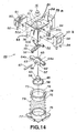
- the third actuating unit 14 has a multi-directional input device 49, as shown in Fig. 14.
- This multi-directional input device 49 has a box-shaped upper frame 50 and an arched first interlock type member 51, as shown in Fig. 14.
- the first interlock type member 51 is rotatably carried by the upper frame 50 by having a warped end portion 52 engaged with a rotary shaft 54 of a first variable resistor 53a operating as a rotary detector secured to a lateral side 50a of the upper frame 50 and by having a lug 55 of the opposite side warped end portion 52 loosely fitted in an opening 56 formed in a lateral side 50b opposite to the lateral side 50a of the frame 50.
- an actuating shaft 57 having a saucer-like operating portion 58 on its lower end and a disc 59 at a mid portion.
- This disc 59 has an orifice 60.
- the upper portion of the actuating shaft 57 is mounted to the rotation actuator 16.
- the second interlock type member 62 for extending at right angles to the actuating shaft 57.
- the second interlock type member 62 has a ball 63 at its center and a pair of arms 64a, 64b extending horizontally with respect to the ball 63.
- the ball 63 has a groove 65 extending from its upper side to its lower side.
- a pin 67 is inserted into the hole 66 and the orifice 60 and the actuating shaft 57 is mounted on the second interlock type member 62 for rotation along the groove 65 with the pin 67 as a supporting shaft.
- the second interlock type member 62 is projected outwards from the lateral side 50c of the upper frame 50 by a rotary shaft 54 of a second variable resistor 53b secured to the lateral side 50c of the upper frame 50 engaging with the end of the arm 64a and by the end of the opposite side arm 64b fitting in an elongated hole 70 formed in the lateral side 50d of the upper frame 50.
- the actuating shaft 57 is passed through the groove 71 of the first interlock type member 51 and subsequently projected outwards via an opening 72 formed in the upper surface of the upper frame 50.
- the actuating shaft 57 is supported on a restoration member 73 which has a saucer-like operating member 58 rotatably housed in its upper surface side recess 74.
- a lower frame 75 is mounted on the lower end of the upper frame 50.
- a supporting wall section 77 for vertically movably housing a flange 76 of the restoration member 73.
- a restoration spring 79 biasing the restoration member 73 upwards.
- the end of the arm 64b of the second interlock type member 62 is caused to compress against the upper edge of the elongated hole 70 in the lateral side 50d of the upper frame 50.
- the second interlock type member 62 is rotatably mounted on the upper frame 50 in a direction perpendicular to the first interlock type member 51 below the first interlock type member 51.
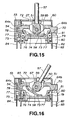
- a thrust type switch element 80 On the lateral side 50d of the upper frame 50 is mounted a thrust type switch element 80 which is changed over by thrusting the spring-biased thrusting actuators 81 against spring bias.
- the thrusting actuators 81 faces the end of the arm 64b of the second interlock type member 62. Its end 82 is projected in the same direction as a mounting leg 83 provided on the lower edge of the upper frame 50 and terminals 84 of the first and second variable resistors 53a, 53b.
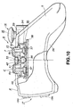
- the operating state of the multi-directional input device 50 is hereinafter explained.
- the actuating shaft 57 is rotated about the point of intersection of the second interlock type member 62 with the pin 67 as the center of rotation. With rotation of the actuating shaft 57, the first interlock type member 51 and the second interlock type member 62 run in rotation.
- the rotary shafts of the first and second variable resistors 53a, 53b are also run n rotation to adjust resistance values.
- the actuating shaft 57 is set upright from the opening 72 in the upper surface of the upper frame 50, with the bottom surface of the operating member 58 compressing against the inner bottom surface of the restoration member 73 by the restoration spring 79.
- the flange 85 having an arcuate portion the radius of curvature of which is progressively increased towards outside of the operating member 58 thrusts the restoration member 73 downwards along the supporting wall section 77 of the lower frame 75 against the elasticity of the restoration spring 79. If the operating pressure on the actuating shaft 57 is relinquished, the neutral state shown in Fig. 15 is restored, that is the actuating shaft 57 is restored to its upstanding state, under the boas of the restoration spring 79.
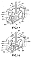
- the actuating shaft 57 in the non-operative state is at a position shown in Fig. 17, in which the end of the arm 64b of the second interlock type member 62 is spaced apart from the thrusting actuators 81 of the switch element 80 and the end of the arm 64b compresses against the upper edge of the elongated opening 70 of the lateral surface 50d of the upper frame 50.
- the end of the arm 64b of the second interlock type member 62 is moved downwards, along the elongated hole 70, against the bias of the restoration spring 79, with the engagement point of the arm 64a with the rotary shaft 54 of the first variable resistor 53a as a fulcrum point, until the end of the arm 64b is retained by the lower edge of the elongated opening 70 operating as a stop.
- the end of the arm 64b thrusts the thrusting actuators 81 of the switch element 80 downwards to change over the state of the switch element 80. If the actuating shaft 57 ceases to be thrust, the end of the arm 64b is restored to the state shown in Fig.
- the third and fourth actuating units 14, 15 can issue the command information of continuously moving the display character, rotating and simultaneously advancing the display character or changing its line of sight.
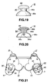
- the rotation actuators 16 for actuating the third and fourth actuating units 14, 15 are provided with a main actuator body portion 86 mounted on the distal end of the actuating shaft 57, as shown in Figs. 19 and 20.
- the main actuator body portion 86 is molded integrally from a synthetic resin material of higher toughness to inhibit deformation.
- the main actuator body portion 86 has a shank portion 86a on the distal end of which an ellipsoidally-shaped head 86b is protuberantly formed and on the proximal end of which a tubular fitting projection 86c is formed so as to serve for mounting the actuating shaft 57.
- a fitting hole 86d extending from the fitting projection 86c to the mid portion of the shank portion 86a and in which is fitted the actuating shaft 57.
- a semi-spherically-shaped flange 86e On the outer rim of the proximal end of the shank portion 86a is protuberantly formed a semi-spherically-shaped flange 86e.
- a top layer 88 formed of a flexible material, as shown in Figs. 19 and 20.
- the material of the top layer 88 may be an elastomer exhibiting rubber-like elasticity.
- the top layer 88 is formed by two-color molding on the head 86b of the main actuator body portion 86.
- the upper surface side of the top layer 88 is arcuately formed towards above for improving the tactile feeling.
- the rotation actuators 16 having the top layer 88 of a flexible material on its portion touched by hand or finger, it is possible to reduce the impact otherwise applied to the hand orb finger when the actuators are thrust, thus improving the operating feeling on acting on the actuators 16.
- the elastomer of the top layer 88 operates as anti-slip in case of actuation of the rotation actuators 16.
- the top layer 88 is integrally formed with the main actuator body portion 86 by two-color molding, the top layer can be positively affixed to the main actuator body portion 86 to prevent exfoliation on repeated thrusting operations.
- the head 86b may also be formed of an elastomer similar to that of the top layer 88.
- the fifth and sixth actuating units 17, 18, provided on the front side of the main body unit 4, are hereinafter explained.
- the first and second thrusting actuators 19a, 19b and 20a, 20b are arranged so that the distal ends of the fifth and sixth actuating units 17, 18 are protruded from the front side of the main body unit 4 via paired upper and lower parallel openings 91 formed in the front sides of the main body unit 4.
- Within the main body unit 4 are provided switch elements in association with the thrusting actuators 19a, 19b and 20a, 20b.
- the portions of the thrusting actuators 19a, 19b and 20a contacted by the hand or finger may similarly be provided with a top layer formed of elastomer.
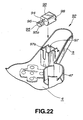
- the actuating device 1 of the present invention is provided with vibration-imparting units 92, 92 for imparting vibration to the user to realize more vivid play feeling.
- These vibration-imparting units 92, 92 are provided on the proximal ends of the first and second grips 5, 6 held by the hand or finger of the user gripping the actuating device 1, as shown in Fig.21.
- These vibration-imparting units 92, 92 are made up of a driving motor 93 driven by driving command signals sent from the main body unit of the game machine and an eccentric member 95 mounted on a driving shaft 94 of the driving motor 93.
- the eccentric member 95 is constituted by a metal member of a large weight mass and a semi-circular weight 95a offset relative to the fitting hole 96 engaged by the driving shaft 94 and which is offset relative to the fitting hole 96.
- the driving motor 93 having the eccentric member 95 mounted on the driving shaft 94 is mounted by having a motor housing 98 fitted in a tubular fitting recess 97 of a rectangular cross-section formed on the inner side of the first grip 5, as shown in Fig.23.
- the driving motor 93 is actuated to run the eccentric member 95 in rotation so that the driving motor 93 is vibrated.
- the vibrations of the driving motor 93 are transmitted via a peripheral wall section 97a of the fitting recess 97 to the first grip 5 to transmit the vibrations to the hand or finger holding the grip 5.
- the driving motors 93 of the vibration-imparting units 92, 92 differ in power rating so that, when the vibration-imparting units 92, 92 are driven by a constant driving voltage, the driving motors differ in rotational speeds such that the eccentric members 95 are rotated at differential speeds to produce vibrations of different frequencies.
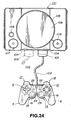
- the actuating device 1 of the game machine according to the present invention is connected to the main body unit 4 of the game machine as shown in Fig.24.
- the actuating device 1 is connected to the main body unit of the game machine 101 via a connection cord 102 pulled out from a mid portion on the front side of the main body unit 4.
- the connection cord 102 has an end connector 103 which is connected to a jack 104 provided on a lateral surface of the main body unit 101 to connect the actuating device 1 to the main body unit of the game machine 101.
- the main body unit of the game machine 101 has plural jacks 104 to enable connection thereof to plural actuating devices 1.
- the main body unit of the game machine 101 has, enclosed therein, a disc driving unit 105 for reproducing an optical disc having a game program recorded thereon, and a picture processing device for displaying the display character, along with the background picture, on the screen of the television receiver in accordance with the game program recorded on the optical disc.
- the main body unit of the game machine 101 also has a reset switch 106 for resetting the game being executed, a power switch 107 and a lid opening button 109 for opening a lid 108 adapted for opening/closing the disc loading unit of the disc driving unit 105.
- the main body unit of the game machine 101 is connected to a television receiver as a display device for displaying the display character along with the background picture.
- the first to sixth actuating units 9, 12, 14, 15, 17 and 18 can be actuated using up to a maximum of 10 fingers, as the first and second grips 5, 6 are held with both hands.
- the actuating device 1 can also be actuated using only one of the first and second grips 5, 6.
- the display character can perform complex movements to execute a game program with a vivid play feeling. It is possible, for example, to realize a game in which an aircraft or a submarine performs a complex movement through a three-dimensional space for play performance along three axes of movements.
Claims (5)
- Dispositif de commande pour une console de jeux comprenant :des première et seconde poignées (5, 6) dépassant depuis un côté de chaque extrémité d'une unité de corps principale (4) du dispositif ;une première unité de commande (9) fournie sur une extrémité de l'unité de corps principale et ayant une pluralité de boutons d'action (8a, 8b, 8c, 8d) dépassant sur un côté de surface supérieure de l'unité de corps principale (4) et une pluralité d'éléments d'entrée de signal (34, 37) actionnés par lesdits boutons d'action ;une deuxième unité de commande (12) fournie sur l'autre extrémité de l'unité de corps principale (4) et ayant une pluralité de boutons d'action (11a, 11b, 11c, 11d) dépassant sur un côté de surface supérieure de l'unité de corps principale et une pluralité d'éléments d'entrée de signal actionnés par lesdits boutons d'action ;caractérisé en ce que
des troisième et quatrième unités de commande (14, 15) agencées l'une face à l'autre sur les extrémités proximales desdites première et seconde poignées (5, 6),
lesdits troisième et quatrième unités de commande (14, 15) étant munies d'un bouton de rotation (16) pouvant tourner sur 360 degrés par rapport à un arbre de commande (57) en tant que centre et un élément d'introduction de signal (80, 53a, 53b) actionné par ce bouton de rotation,
lesdits boutons de rotation (16) ayant chacun une partie de corps de bouton de commande principale (86) en résine synthétique et une couche supérieure (88) en matériau flexible étant formée d'un seul tenant avec ladite partie de corps de bouton de commande principale (86) sur son côté de surface supérieure. - Dispositif de commande pour une console de jeux selon la revendication 1, dans lequel la partie corps de bouton de commande principale (86) et la partie supérieure (88) se composent d'une pièce obtenue par moulage bicolore.
- Dispositif de commande pour une console de jeux selon la revendication 1 dans lequel les surfaces supérieures des boutons d'action (8a, 8b, 8c, 8d) sont formées d'un seul tenant avec les parties supérieures (7) en matériau flexible.
- Dispositif de commande pour une console de jeux selon la revendication 1 dans lequel les unités de transmission de vibrations (92) comprennent chacune un moteur d'entraînement (93) et un excentrique (95) montés sur un arbre d'entraînement (94) du moteur d'entraînement.
- Dispositif de commande pour une console de jeux selon la revendication 4 dans lequel les unités de transmission de vibrations (92) fournies dans les première et seconde poignées (5, 6) sont de configurations de transmission de vibrations différentes.
Applications Claiming Priority (3)
| Application Number | Priority Date | Filing Date | Title |
|---|---|---|---|
| JP25721697 | 1997-09-22 | ||
| JP9257216A JPH1190042A (ja) | 1997-09-22 | 1997-09-22 | ゲーム機用操作装置 |
| JP257216/97 | 1997-09-22 |
Publications (3)
| Publication Number | Publication Date |
|---|---|
| EP0903659A2 EP0903659A2 (fr) | 1999-03-24 |
| EP0903659A3 EP0903659A3 (fr) | 2003-10-29 |
| EP0903659B1 true EP0903659B1 (fr) | 2006-11-29 |
Family
ID=17303286
Family Applications (1)
| Application Number | Title | Priority Date | Filing Date |
|---|---|---|---|
| EP98117834A Expired - Lifetime EP0903659B1 (fr) | 1997-09-22 | 1998-09-21 | Dispositif de commande pour une console de jeux |
Country Status (13)
| Country | Link |
|---|---|
| US (1) | US6394906B1 (fr) |
| EP (1) | EP0903659B1 (fr) |
| JP (1) | JPH1190042A (fr) |
| KR (1) | KR100627768B1 (fr) |
| CN (1) | CN1139417C (fr) |
| AU (1) | AU752420B2 (fr) |
| CA (1) | CA2247718C (fr) |
| DE (1) | DE69836525T2 (fr) |
| ES (1) | ES2273389T3 (fr) |
| HK (1) | HK1017746A1 (fr) |
| MY (1) | MY125892A (fr) |
| SG (1) | SG68688A1 (fr) |
| TW (1) | TW369431B (fr) |
Families Citing this family (63)
| Publication number | Priority date | Publication date | Assignee | Title |
|---|---|---|---|---|
| US6222525B1 (en) | 1992-03-05 | 2001-04-24 | Brad A. Armstrong | Image controllers with sheet connected sensors |
| US8674932B2 (en) | 1996-07-05 | 2014-03-18 | Anascape, Ltd. | Image controller |
| CN1132646C (zh) * | 1996-10-11 | 2003-12-31 | 索尼计算机娱乐株式会社 | 游戏机用操作装置 |
| JP2000084250A (ja) * | 1998-09-16 | 2000-03-28 | Taito Corp | ゲーム機の衝撃感発生装置 |
| JP2001137544A (ja) * | 1999-08-27 | 2001-05-22 | Sony Computer Entertainment Inc | エンタテインメントシステム、エンタテインメント装置、記録媒体及びプログラム |
| DE20080209U1 (de) | 1999-09-28 | 2001-08-09 | Immersion Corp | Steuerung von haptischen Empfindungen für Schnittstellenvorrichtungen mit Vibrotaktiler Rückkopplung |
| JP2001113048A (ja) * | 1999-10-14 | 2001-04-24 | Sony Corp | ゲーム機用操作装置 |
| JP2001143556A (ja) * | 1999-11-12 | 2001-05-25 | Sony Computer Entertainment Inc | 操作装置 |
| JP3260348B2 (ja) * | 2000-02-17 | 2002-02-25 | 株式会社アスキー | コントローラ用アタッチメントおよびゲーム機 |
| JP3428564B2 (ja) * | 2000-05-17 | 2003-07-22 | 日本電気株式会社 | 折り畳み式携帯通信装置 |
| JP2002095863A (ja) * | 2000-07-03 | 2002-04-02 | Sony Computer Entertainment Inc | プログラム実行システム、プログラム実行装置、記録媒体及びプログラム、並びに視点を切り換える方法及び照準を切り換える方法 |
| US7084854B1 (en) | 2000-09-28 | 2006-08-01 | Immersion Corporation | Actuator for providing tactile sensations and device for directional tactile sensations |
| WO2002027705A1 (fr) * | 2000-09-28 | 2002-04-04 | Immersion Corporation | Retroaction tactile directionnelle destinee a des dispositifs d'interface a retroaction haptique |
| US6641480B2 (en) | 2001-01-29 | 2003-11-04 | Microsoft Corporation | Force feedback mechanism for gamepad device |
| JP3608726B2 (ja) * | 2001-04-19 | 2005-01-12 | 株式会社ソニー・コンピュータエンタテインメント | コントローラ |
| US6524188B2 (en) * | 2001-06-26 | 2003-02-25 | Yung-Chung Wang | Game controller with a monitor |
| US6888537B2 (en) * | 2002-02-13 | 2005-05-03 | Siemens Technology-To-Business Center, Llc | Configurable industrial input devices that use electrically conductive elastomer |
| JP3457305B1 (ja) * | 2002-09-19 | 2003-10-14 | 株式会社コナミコンピュータエンタテインメント東京 | ゲーム装置、ゲーム制御方法及びプログラム |
| US20060148374A1 (en) * | 2003-01-17 | 2006-07-06 | Nikko Co., Ltd. | Transmitter for wireless control |
| EP1560238B1 (fr) * | 2004-01-27 | 2007-02-28 | Hsien-Ta Huang | Dispositif de commande portatif absorbant les chocs |
| US20050174337A1 (en) * | 2004-02-11 | 2005-08-11 | Nielsen Paul S. | Electronic handheld drawing and gaming system using television monitor |
| US7167159B2 (en) * | 2004-07-01 | 2007-01-23 | Geltabz, Inc. | Joystick cover |
| US7535464B1 (en) * | 2004-08-30 | 2009-05-19 | Microsoft Corporation | Navigation wheel having discrete switches |
| US7859514B1 (en) | 2005-07-19 | 2010-12-28 | Young Park | Multi-functional user interface for electronic devices |
| CN101278244B (zh) * | 2005-10-06 | 2012-05-30 | Abb股份有限公司 | 用于工业机器人的控制系统和示教盒 |
| US8108092B2 (en) | 2006-07-14 | 2012-01-31 | Irobot Corporation | Autonomous behaviors for a remote vehicle |
| US7843431B2 (en) | 2007-04-24 | 2010-11-30 | Irobot Corporation | Control system for a remote vehicle |
| US20090225028A1 (en) * | 2008-02-26 | 2009-09-10 | Clem Abrams | Point and click device for computer |
| US8014148B2 (en) * | 2008-02-28 | 2011-09-06 | Panasonic Corporation | Electronic device |
| JP2012120716A (ja) * | 2010-12-09 | 2012-06-28 | Pilot Ink Co Ltd | 絵合せ玩具及び絵合せ玩具セット |
| US8803803B2 (en) | 2011-01-25 | 2014-08-12 | Sony Corporation | Operation member provided in electronic device, and electronic device |
| CN102671375B (zh) * | 2011-03-09 | 2015-06-03 | 台达电子工业股份有限公司 | 按键控制器 |
| US8641525B2 (en) * | 2011-06-17 | 2014-02-04 | Ironburg Inventions Ltd. | Controller for video game console |
| CN102274635A (zh) * | 2011-07-30 | 2011-12-14 | 周海涛 | 一种游戏控制器 |
| JP5941276B2 (ja) * | 2011-12-09 | 2016-06-29 | アルプス電気株式会社 | 多方向入力装置 |
| WO2013136960A1 (fr) * | 2012-03-13 | 2013-09-19 | 株式会社ソニー・コンピュータエンタテインメント | Dispositif d'actionnement |
| CN104205278B (zh) | 2012-03-13 | 2017-03-08 | 索尼电脑娱乐公司 | 操作设备 |
| JP6063201B2 (ja) | 2012-10-15 | 2017-01-18 | 株式会社ソニー・インタラクティブエンタテインメント | 操作デバイス |
| US9690392B2 (en) | 2012-10-15 | 2017-06-27 | Sony Corporation | Operating device including a touch sensor |
| KR102249208B1 (ko) * | 2012-10-15 | 2021-05-10 | 주식회사 소니 인터랙티브 엔터테인먼트 | 조작 디바이스 |
| US10328344B2 (en) | 2013-10-11 | 2019-06-25 | Valve Corporation | Game controller systems and methods |
| KR101397457B1 (ko) * | 2014-02-28 | 2014-05-21 | 강신권 | 게임 조정장치 |
| DE102015102317A1 (de) * | 2015-02-18 | 2016-08-18 | Elobau Gmbh & Co. Kg | Joystick |
| JP6209575B2 (ja) * | 2015-04-24 | 2017-10-04 | 任天堂株式会社 | 多方向入力装置 |
| US9921652B2 (en) * | 2015-06-29 | 2018-03-20 | Apple Inc. | Input with haptic feedback |
| US9971407B2 (en) | 2015-09-30 | 2018-05-15 | Apple Inc. | Haptic feedback for rotary inputs |
| US10503258B2 (en) | 2016-03-04 | 2019-12-10 | Apple Inc. | Input mechanism with force and rotation inputs and haptic feedback |
| WO2017212663A1 (fr) * | 2016-06-10 | 2017-12-14 | 任天堂株式会社 | Dispositif de commande de jeu |
| JP6782567B2 (ja) | 2016-06-10 | 2020-11-11 | 任天堂株式会社 | ゲームコントローラ |
| JP6677580B2 (ja) | 2016-06-10 | 2020-04-08 | 任天堂株式会社 | ゲームコントローラ |
| JP7083226B2 (ja) | 2016-06-10 | 2022-06-10 | 任天堂株式会社 | ゲームコントローラ |
| EP3254739B1 (fr) | 2016-06-10 | 2020-03-25 | Nintendo Co., Ltd. | Contrôleur de jeu |
| JP6893763B2 (ja) | 2016-06-10 | 2021-06-23 | 任天堂株式会社 | ゲームコントローラ |
| US10406431B2 (en) | 2016-08-11 | 2019-09-10 | Valve Corporation | Hand-held controller with a back shell and underlying force sensitive resistors |
| US10722786B2 (en) | 2016-08-11 | 2020-07-28 | Valve Corporation | Video game controller with unitary back shell for button control and battery access |
| US11794094B2 (en) | 2016-10-17 | 2023-10-24 | Aquimo Inc. | Method and system for using sensors of a control device for control of a game |
| WO2019032042A1 (fr) | 2017-08-11 | 2019-02-14 | Razer (Asia-Pacific) Pte. Ltd. | Extension de hauteur de stick analogique |
| CN108766122B (zh) * | 2018-06-22 | 2020-06-05 | 常州轻工职业技术学院 | 一种用触觉提高英语发音质量的装置 |
| CA201150S (en) | 2021-02-08 | 2022-10-19 | Collective Minds Gaming Co Ltd | Adapter for a video game controller |
| USD983200S1 (en) | 2021-02-08 | 2023-04-11 | Collective Minds Gaming Co. Ltd. | Stop for a trigger button of a video game controller |
| WO2023047472A1 (fr) | 2021-09-21 | 2023-03-30 | 株式会社ソニー・インタラクティブエンタテインメント | Dispositif d'entrée possédant une poignée réglable |
| WO2023171225A1 (fr) * | 2022-03-08 | 2023-09-14 | アルプスアルパイン株式会社 | Dispositif d'entrée multidirectionnel |
| USD978970S1 (en) * | 2022-10-31 | 2023-02-21 | Lisong Qiu | Game controller |
Family Cites Families (15)
| Publication number | Priority date | Publication date | Assignee | Title |
|---|---|---|---|---|
| US4486629A (en) * | 1983-07-18 | 1984-12-04 | Coleco Industries, Inc. | Joystick controller |
| JPS6244339U (fr) * | 1985-08-31 | 1987-03-17 | ||
| JPS62194389A (ja) | 1986-02-21 | 1987-08-26 | ミクストン株式会社 | 回転昇降扉 |
| JP2615607B2 (ja) * | 1987-04-07 | 1997-06-04 | ソニー株式会社 | 入力操作装置 |
| US5701142A (en) * | 1990-07-24 | 1997-12-23 | In-Control Solutions, Inc. | Pointing stick with tripod actuator for cursor control in a computer keyboard |
| US5468924A (en) * | 1993-07-01 | 1995-11-21 | Sumitomo Wiring Systems, Ltd. | Joy stick support structure for multi-directional switch |
| US5555004A (en) * | 1993-08-30 | 1996-09-10 | Hosiden Corporation | Input control device |
| JPH0788252A (ja) | 1993-09-22 | 1995-04-04 | Sony Corp | ゲーム機用操作装置 |
| JP2533285B2 (ja) | 1993-10-14 | 1996-09-11 | コナミ株式会社 | テレビゲ―ム機の光線銃 |
| US5473126A (en) * | 1994-01-31 | 1995-12-05 | Wu; Donald | Joystick switch assembly |
| US6004134A (en) * | 1994-05-19 | 1999-12-21 | Exos, Inc. | Interactive simulation including force feedback |
| JP4036246B2 (ja) * | 1994-08-02 | 2008-01-23 | 任天堂株式会社 | ゲーム機用操作装置 |
| US5670955A (en) * | 1995-01-31 | 1997-09-23 | Microsoft Corporation | Method and apparatus for generating directional and force vector in an input device |
| CN1149465C (zh) * | 1995-10-09 | 2004-05-12 | 任天堂株式会社 | 三维图像显示游戏机系统和三维图像处理方法 |
| US5801918A (en) * | 1996-07-12 | 1998-09-01 | Hand Held Products, Inc. | Ergonomic housing for a micro computer |
-
1997
- 1997-09-22 JP JP9257216A patent/JPH1190042A/ja active Pending
-
1998
- 1998-09-15 TW TW087115357A patent/TW369431B/zh not_active IP Right Cessation
- 1998-09-15 AU AU84242/98A patent/AU752420B2/en not_active Expired
- 1998-09-17 SG SG1998003709A patent/SG68688A1/en unknown
- 1998-09-21 EP EP98117834A patent/EP0903659B1/fr not_active Expired - Lifetime
- 1998-09-21 MY MYPI98004340A patent/MY125892A/en unknown
- 1998-09-21 ES ES98117834T patent/ES2273389T3/es not_active Expired - Lifetime
- 1998-09-21 KR KR1019980039000A patent/KR100627768B1/ko not_active IP Right Cessation
- 1998-09-21 DE DE69836525T patent/DE69836525T2/de not_active Expired - Lifetime
- 1998-09-21 CA CA002247718A patent/CA2247718C/fr not_active Expired - Lifetime
- 1998-09-22 CN CNB981195415A patent/CN1139417C/zh not_active Expired - Lifetime
- 1998-09-22 US US09/158,062 patent/US6394906B1/en not_active Expired - Lifetime
-
1999
- 1999-07-02 HK HK99102800A patent/HK1017746A1/xx not_active IP Right Cessation
Also Published As
| Publication number | Publication date |
|---|---|
| US6394906B1 (en) | 2002-05-28 |
| CN1220905A (zh) | 1999-06-30 |
| CA2247718C (fr) | 2008-01-29 |
| EP0903659A3 (fr) | 2003-10-29 |
| JPH1190042A (ja) | 1999-04-06 |
| AU752420B2 (en) | 2002-09-19 |
| KR19990029997A (ko) | 1999-04-26 |
| DE69836525D1 (de) | 2007-01-11 |
| HK1017746A1 (en) | 1999-11-26 |
| EP0903659A2 (fr) | 1999-03-24 |
| DE69836525T2 (de) | 2007-12-13 |
| KR100627768B1 (ko) | 2007-07-09 |
| CA2247718A1 (fr) | 1999-03-22 |
| CN1139417C (zh) | 2004-02-25 |
| ES2273389T3 (es) | 2007-05-01 |
| TW369431B (en) | 1999-09-11 |
| MY125892A (en) | 2006-08-30 |
| SG68688A1 (en) | 1999-11-16 |
| AU8424298A (en) | 1999-04-15 |
Similar Documents
| Publication | Publication Date | Title |
|---|---|---|
| EP0903659B1 (fr) | Dispositif de commande pour une console de jeux | |
| US6231444B1 (en) | Operating device for game machine | |
| US6171191B1 (en) | Actuating device and system exploiting the actuating device | |
| JP3628358B2 (ja) | ゲーム機用コントローラ | |
| US6589118B1 (en) | Analog input device to input multi directional signals | |
| US5012230A (en) | Input device for digital processor based apparatus | |
| JPH08180770A (ja) | ゲーム機用操作装置 | |
| JP2001143556A (ja) | 操作装置 | |
| JPH06139878A (ja) | テレビゲーム機用コントローラ | |
| JP3380233B2 (ja) | ゲーム機用コントローラ | |
| JP3453263B2 (ja) | ゲーム機用操作装置 | |
| AU9707001A (en) | Operating device for game machine | |
| MXPA98007711A (en) | Drive device for thread machine | |
| JPH0975544A (ja) | ゲーム機用コントローラ | |
| JPH1085455A (ja) | ゲームシステム |
Legal Events
| Date | Code | Title | Description |
|---|---|---|---|
| PUAI | Public reference made under article 153(3) epc to a published international application that has entered the european phase |
Free format text: ORIGINAL CODE: 0009012 |
|
| AK | Designated contracting states |
Kind code of ref document: A2 Designated state(s): AT BE CH CY DE DK ES FI FR GB GR IE IT LI LU MC NL PT SE |
|
| AX | Request for extension of the european patent |
Free format text: AL;LT;LV;MK;RO;SI |
|
| PUAL | Search report despatched |
Free format text: ORIGINAL CODE: 0009013 |
|
| AK | Designated contracting states |
Kind code of ref document: A3 Designated state(s): AT BE CH CY DE DK ES FI FR GB GR IE IT LI LU MC NL PT SE |
|
| AX | Request for extension of the european patent |
Extension state: AL LT LV MK RO SI |
|
| 17P | Request for examination filed |
Effective date: 20040329 |
|
| 17Q | First examination report despatched |
Effective date: 20040518 |
|
| AKX | Designation fees paid |
Designated state(s): DE ES FR GB IT NL |
|
| GRAP | Despatch of communication of intention to grant a patent |
Free format text: ORIGINAL CODE: EPIDOSNIGR1 |
|
| GRAS | Grant fee paid |
Free format text: ORIGINAL CODE: EPIDOSNIGR3 |
|
| GRAA | (expected) grant |
Free format text: ORIGINAL CODE: 0009210 |
|
| AK | Designated contracting states |
Kind code of ref document: B1 Designated state(s): DE ES FR GB IT NL |
|
| REG | Reference to a national code |
Ref country code: GB Ref legal event code: FG4D |
|
| REF | Corresponds to: |
Ref document number: 69836525 Country of ref document: DE Date of ref document: 20070111 Kind code of ref document: P |
|
| REG | Reference to a national code |
Ref country code: HK Ref legal event code: GR Ref document number: 1017746 Country of ref document: HK |
|
| REG | Reference to a national code |
Ref country code: ES Ref legal event code: FG2A Ref document number: 2273389 Country of ref document: ES Kind code of ref document: T3 |
|
| ET | Fr: translation filed | ||
| PLBE | No opposition filed within time limit |
Free format text: ORIGINAL CODE: 0009261 |
|
| STAA | Information on the status of an ep patent application or granted ep patent |
Free format text: STATUS: NO OPPOSITION FILED WITHIN TIME LIMIT |
|
| 26N | No opposition filed |
Effective date: 20070830 |
|
| REG | Reference to a national code |
Ref country code: FR Ref legal event code: PLFP Year of fee payment: 19 |
|
| REG | Reference to a national code |
Ref country code: FR Ref legal event code: PLFP Year of fee payment: 20 |
|
| PGFP | Annual fee paid to national office [announced via postgrant information from national office to epo] |
Ref country code: NL Payment date: 20170814 Year of fee payment: 20 |
|
| PGFP | Annual fee paid to national office [announced via postgrant information from national office to epo] |
Ref country code: IT Payment date: 20170925 Year of fee payment: 20 Ref country code: FR Payment date: 20170810 Year of fee payment: 20 Ref country code: GB Payment date: 20170920 Year of fee payment: 20 Ref country code: DE Payment date: 20170912 Year of fee payment: 20 |
|
| PGFP | Annual fee paid to national office [announced via postgrant information from national office to epo] |
Ref country code: ES Payment date: 20171005 Year of fee payment: 20 |
|
| REG | Reference to a national code |
Ref country code: DE Ref legal event code: R071 Ref document number: 69836525 Country of ref document: DE |
|
| REG | Reference to a national code |
Ref country code: NL Ref legal event code: MK Effective date: 20180920 |
|
| REG | Reference to a national code |
Ref country code: GB Ref legal event code: PE20 Expiry date: 20180920 |
|
| PG25 | Lapsed in a contracting state [announced via postgrant information from national office to epo] |
Ref country code: GB Free format text: LAPSE BECAUSE OF EXPIRATION OF PROTECTION Effective date: 20180920 |
|
| REG | Reference to a national code |
Ref country code: ES Ref legal event code: FD2A Effective date: 20220127 |
|
| PG25 | Lapsed in a contracting state [announced via postgrant information from national office to epo] |
Ref country code: ES Free format text: LAPSE BECAUSE OF EXPIRATION OF PROTECTION Effective date: 20180922 |