EP0903654A2 - Steuerungssystem für insbesondere Palettieranlagen mit Robotern - Google Patents
Steuerungssystem für insbesondere Palettieranlagen mit Robotern Download PDFInfo
- Publication number
- EP0903654A2 EP0903654A2 EP98116930A EP98116930A EP0903654A2 EP 0903654 A2 EP0903654 A2 EP 0903654A2 EP 98116930 A EP98116930 A EP 98116930A EP 98116930 A EP98116930 A EP 98116930A EP 0903654 A2 EP0903654 A2 EP 0903654A2
- Authority
- EP
- European Patent Office
- Prior art keywords
- control
- robot
- control component
- functions
- plc
- Prior art date
- Legal status (The legal status is an assumption and is not a legal conclusion. Google has not performed a legal analysis and makes no representation as to the accuracy of the status listed.)
- Granted
Links
Images


Classifications
-
- G—PHYSICS
- G05—CONTROLLING; REGULATING
- G05B—CONTROL OR REGULATING SYSTEMS IN GENERAL; FUNCTIONAL ELEMENTS OF SUCH SYSTEMS; MONITORING OR TESTING ARRANGEMENTS FOR SUCH SYSTEMS OR ELEMENTS
- G05B19/00—Program-control systems
- G05B19/02—Program-control systems electric
- G05B19/418—Total factory control, i.e. centrally controlling a plurality of machines, e.g. direct or distributed numerical control [DNC], flexible manufacturing systems [FMS], integrated manufacturing systems [IMS] or computer integrated manufacturing [CIM]
-
- B—PERFORMING OPERATIONS; TRANSPORTING
- B65—CONVEYING; PACKING; STORING; HANDLING THIN OR FILAMENTARY MATERIAL
- B65G—TRANSPORT OR STORAGE DEVICES, e.g. CONVEYORS FOR LOADING OR TIPPING, SHOP CONVEYOR SYSTEMS OR PNEUMATIC TUBE CONVEYORS
- B65G57/00—Stacking of articles
- B65G57/02—Stacking of articles by adding to the top of the stack
- B65G57/03—Stacking of articles by adding to the top of the stack from above
-
- B—PERFORMING OPERATIONS; TRANSPORTING
- B25—HAND TOOLS; PORTABLE POWER-DRIVEN TOOLS; MANIPULATORS
- B25J—MANIPULATORS; CHAMBERS PROVIDED WITH MANIPULATION DEVICES
- B25J13/00—Controls for manipulators
- B25J13/06—Control stands, e.g. consoles, switchboards
-
- G—PHYSICS
- G05—CONTROLLING; REGULATING
- G05B—CONTROL OR REGULATING SYSTEMS IN GENERAL; FUNCTIONAL ELEMENTS OF SUCH SYSTEMS; MONITORING OR TESTING ARRANGEMENTS FOR SUCH SYSTEMS OR ELEMENTS
- G05B19/00—Program-control systems
- G05B19/02—Program-control systems electric
- G05B19/18—Numerical control [NC], i.e. automatically operating machines, in particular machine tools, e.g. in a manufacturing environment, so as to execute positioning, movement or co-ordinated operations by means of program data in numerical form
- G05B19/414—Structure of the control system, e.g. common controller or multiprocessor systems, interface to servo, programmable interface controller
-
- Y—GENERAL TAGGING OF NEW TECHNOLOGICAL DEVELOPMENTS; GENERAL TAGGING OF CROSS-SECTIONAL TECHNOLOGIES SPANNING OVER SEVERAL SECTIONS OF THE IPC; TECHNICAL SUBJECTS COVERED BY FORMER USPC CROSS-REFERENCE ART COLLECTIONS [XRACs] AND DIGESTS
- Y02—TECHNOLOGIES OR APPLICATIONS FOR MITIGATION OR ADAPTATION AGAINST CLIMATE CHANGE
- Y02P—CLIMATE CHANGE MITIGATION TECHNOLOGIES IN THE PRODUCTION OR PROCESSING OF GOODS
- Y02P90/00—Enabling technologies with a potential contribution to greenhouse gas [GHG] emissions mitigation
- Y02P90/02—Total factory control, e.g. smart factories, flexible manufacturing systems [FMS] or integrated manufacturing systems [IMS]
Definitions
- the invention relates to a control system for robots, in particular for palletizing systems with robots, one robot and palletizing system components via a data transmission device are connected to a control device.
- Control systems for in particular palletizing systems with robots are well known.
- the control device consists of three different ones Assemblies, namely a robot sequence control system, one PLC unit and an external control panel.
- the link of these three modules with each other and the connection of the same to a data transmission device requires one great effort as well as human resources, because the three assemblies above laboriously wired together on the hardware side Need to become.
- the constant data exchange between them three modules (hardware) is also very time consuming and limited thus the performance of the palletizing system.
- Another disadvantage is that different assemblies as well Mastered and maintained programming languages for these modules Need to become.
- the present invention has the problem the basis, a maintainable with little effort as well as maintainable control system that furthermore increased flexibility with regard to the number of the packing samples to be processed.
- control system is used to solve this problem characterized in that the control device as a microprocessor system, especially as an industrial personal computer, is formed, the microprocessor system all control device functions, in particular Functions of a robot sequence control, a PLC and one Control panels, implemented to control the palletizing systems.
- the storage space of the control system becomes the control device significantly increased because of the storage capacity not due to the finite memory size of individual hardware modules is restricted. It can therefore be almost any number of packing samples can be processed.
- the microprocessor system all control device functions, in particular the functions of the robot sequence control, the PLC and the control panel, in software realized, only needs one assembly, namely that Microprocessor system, wired to the data transmission device become. As a result, the control system is less Effort can be put into operation, maintained and maintained.
- the functions of the robot sequence control and are preferably the control panel together as a first control component implemented in software on the microprocessor system.
- the PLC functions are part of a second control component also implemented in software on the microprocessor system. It follows that on the microprocessor system only mastered two control components implemented as software and need to be taken care of. This also simplifies this the commissioning, care and maintenance of the control system considerably.
- FIG. 1 schematically shows the hardware concept of a control system 10 for a palletizing system with robots, such as in US 5 348 440 and US 5 232 332.
- Palletizing robot 11 is via a data transmission device 12 connected to a control device 13.
- 1 is the palletizing robot 11, namely its motor control 14, via an I / O module (input / output module) 15 on the Data transmission device 12 coupled.
- the control device 13 is also connected via an I / O module 16 the data transmission device 12 coupled.
- a gripper 17 of the palletizing robot 11 via a corresponding I / O module 18 coupled to the data transmission device 12.
- the control device 13 of the control system 10 is according to the invention as a microprocessor system, namely as an industrial personal computer 23, trained.
- the industrial personal computer 23 implements all control device functions for controlling the palletizing system with the palletizing robot 11. This includes functions of a robot sequence control, a programmable logic controller (PLC) and a control panel. These functions are on the industrial personal computer 23 all implemented in software.
- PLC programmable logic controller
- the industrial personal computer 23 replaces those required in previously known control systems three separate assemblies robot sequence control, PLC unit and external control panel.
- Fig. 2 shows a schematic block diagram for the on the industrial personal computer 23 realized as software Functions for controlling the palletizing system.
- a first Control components 24 are on the industrial personal computer 23 together the functions of the robot sequence control as well of the control panel.
- the functions of the PLC, however are part of a second control component 25 on the industrial personal computer 23 realized.
- First control component 24 and second control component 25 are on the Industrial personal computer 23 implemented independently of one another.
- the core of the first control component 24 is a robot programming language interpreter, especially an IRL interpreter 26.
- the Industrial Robot Language Interpreter (IRL) implements functions of robot sequence control and of the control panel in software.
- the IRL interpreter has a control panel module 27.
- the functions of the robot sequence control are by a positioning module 28 and a module 29 for additional functions realized. With the help of module 29 for the additional functions
- the palletizing robot 11 can be time-optimized be positioned.
- the second control component 25 is a Real-time platform, which therefore works in real time. part the second control component 25 is a PLC compiler 30, of the functions of the PLC.
- Both the IRL interpreter 26 and the PLC compiler 30 are via files to the palletizing robot 11 to be specifically controlled customizable.
- the PLC compiler is the PLC file 31.
- the IRL interpreter is the files 32, 33.
- File 32 is also referred to as an IRL program file, the file 33, however, as a control panel file.
- First control component 24 and second control component 25 communicate via appropriate software interfaces.
- a PLC task 34 generated by the PLC compiler 30 is executed by a separate PLC module 35 of the IRL interpreter 26 called.
- the PLC task 34 of the second control component 25 and the PLC module 35 of the first control component 24 swap here Data from.
- Another data exchange between the first Control component 24 and the second control component 25 takes place between the positioning module 28 of the first Control component 24 and a positioning task 36 of the second control component 25.
- the module 29 for additional functions of the first control component 24 a suitable interface data to a module 37 of the second Transfer control component 25 back and forth.
- the PLC task 34 With the help of the PLC task 34 generated by the PLC compiler 30 all peripheral components of the palletizing system namely the Gripper 17, the feed table 19 and the tilting device 20 etc. controlled. Furthermore, for example, the emergency stop circuit monitored for the feed table 19 and the gripper 17.
- the PLC task 34 becomes cyclical in an adjustable real-time cycle run through.
- the IRL interpreter generates function calls for PLC task 34 and positioning task 36. Functions of the control panel are as control panel module 27 in the IRL interpreter realized. After each IRL command, the control panel is called.
- FIG. 4 shows.
- the PLC functions are always independent of the through functions performed by the IRL interpreter 26.
- the IRL interpreter 26 of the first control component 24 works all IRL commands by the positioning module 28 and the Module 29 for additional functions continuously.
- the positioning task 36 or module 37 the accept the commands generated by the IRL interpreter 26 and real-time control commands for the palletizing robot 11 to generate.
- From the real-time positioning task 36 are the positioning commands via the I / O module (Input / output module) 15 to the motor control 14 of the Palletizing robot 11 handed over.
- the PLC task 34 generates analogously real-time control commands for the gripper 17 of the palletizing robot 11 and for the feed table 19 and the tilting device 20.
- the data transfer takes place via the I / O modules 18, 21 and 22.
- a file 38 which is also referred to as a configuration file, machine data the palletizing system to be controlled including the robot 11, its gripper 17, the feed table 19 and the tilting device 20 set.
- a second A corresponding PLC program is written in the step in the PLC file 31.
- the files 31, 38 are therefore used for configuration the second control component 25, which operates in real time.
- the file 32 namely in an appropriate IRL program is created for the IRL program file. Only after this is a fourth step in the File 33 made a configuration for the control panel.
- the Machine data set in the file 38 for the machine to be controlled Palletizing robot 11 and the peripheral components of the Plant will be the second via a suitable interface Control component 25 passed and in a corresponding Module 39 of the same ready for further processing.
- the adaptation of the control system to that of the one to be controlled Palletizing robots 11 packing patterns to be handled are usually carried out via a third control component 40 it is preferably an external personal computer.
- the third control component 40 includes one from the end user freely programmable palletizing system 41, with the help of it a file 42 for packing patterns can be generated.
- the third Control component is an external PC with an off-line palletizing system.
- the file 42 for the packing pattern is from a data memory assigned to the IRL interpreter 26 43 read. Since the IRL interpreter 26 as before shown several times on an industrial personal computer is realized, the data memory 43 has a very large capacity, so that almost any number of Files 42 for packing patterns are stored and processed can.
- file 42 in the teach process to generate directly on the IRL interpreter 26.
- Fig. 2 block diagram shown is for one by its nature Operating system not capable of multitasking (e.g. DOS) or a Single-task operating system designed. From targeting such a single-task operating system results in a monolithic Structure of the software with limited changeability and scalability of the software in terms of certain Conditions.
- Operating system not capable of multitasking e.g. DOS
- Single-task operating system designed From targeting such a single-task operating system results in a monolithic Structure of the software with limited changeability and scalability of the software in terms of certain Conditions.
- the first control component 24 according to FIG. 2 is in FIG. 5 divided into an interpreter module 26 together with a module for additional functions 29, positioning module 28 and PLC module 35, and a Robot control module 44.
- COM Component Object Model
- the control module 44 is designed as a tool for technicians, which retract or put the machine into operation. It is used to display user output and program errors. These tasks are performed according to the single task based system Fig. 2 executed by the IRL module.
- the evaluation or preprocessing of the from IRL module 26 sent motion commands made on what the single-task-based system according to FIG. 2 in the second Control component 25 takes place. This evaluation of the movement commands is used to prepare for movement and is used as Control module 44 arranged block 44a shown the data receives via the interface 46.
- the one in the control module Block 44b arranged 44 represents a user interface represents the data between control module 44 and interface 46 exchanges.
- a block 44c is also in the control module 44 integrated, which represents a PLC module that data the PLC task 34 is transmitted.
- the robot control module 44 is also the only module (next to the visualization module or control panel 47) that with communicates with a real-time task. Acting in the real-time task z. B. the positioning task 36 or the PLC task 34.
- the visualization module or control panel 47 also runs independently Program. This makes you not like single-task based Control, to a specific, specially coordinated Control panel software instructed. Rather you can on use any (standard) program packages.
- the visualization module or control panel 47 receives configuration data from a file 33. It is contrary to that shown in Fig. 2 System detached from the first control component 24 as fourth control component realizes and communicates with the first control component 24 via the software interface 46.
- Real-time software is used for the multi-task-based Rotoberober Entry used. It is possible to have several PLC tasks to run in parallel. Due to the opposite of that in FIG. 2 shown modified structure of the real-time software results the possibility of the structure of that shown in Fig. 2 Position module to change.
- 6 module shown for the multi-task system according to FIG. 5 only in the form of a universally usable basic functionality embedded in the real-time core 48.
- Linear method 49 PTP (point to point) method 50 or other method 51, as additional PLC tasks 52 implemented.
- PTP point to point
- This enables a developer to only without a modification to the real-time core 48 Change a positioning program to a PLC program change and add. Since the positioning of the axes as independent PLC program is running in its own task nevertheless an encapsulation compared to the "normal", for control given the necessary PLC program.
- FIG. 6 also shows a second PLC task 53 for the system control 54.
- This system controller 54 communicates with the Real-time core 48 with real-time module 55.
- control device 13 With increased functionality and Speed of the palletizing robot 11 three previously separate Hardware components replaced. Accordingly, the entire palletizing system programmed from a central control device and be controlled. By using the industrial personal computer 23 stands as control device 13 Furthermore, an almost unlimited storage capacity is available. There can therefore be a large number of files about packing patterns be kept ready. This will make the control system very flexible. Furthermore, it should be noted that the industrial personal computer simply and quickly to the data transmission device 12, especially the fiber optic bus leaves. The wiring effort and commissioning effort of the control system 10 is accordingly small.
Landscapes
- Engineering & Computer Science (AREA)
- General Physics & Mathematics (AREA)
- Automation & Control Theory (AREA)
- Mechanical Engineering (AREA)
- Manufacturing & Machinery (AREA)
- Physics & Mathematics (AREA)
- Human Computer Interaction (AREA)
- Robotics (AREA)
- General Engineering & Computer Science (AREA)
- Quality & Reliability (AREA)
- Numerical Control (AREA)
- Manipulator (AREA)
- Programmable Controllers (AREA)
- General Factory Administration (AREA)
- Control By Computers (AREA)
Abstract
Description
- Fig. 1
- eine schematisierte Darstellung einer Palettier-Anlage aus Steuerungseinrichtung, Palettier-Roboter mit Greifer sowie Zuführtisch mit Kippeinrichtung,
- Fig. 2
- ein schematisiertes Blockschaltbild eines Steuerungssystems für die Palettier-Anlage, inklusive des Palettier-Roboters,
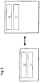
- Fig. 3
- ein schematisiertes Blockdiagramm für die Konfiguration des Steuerungssystems,
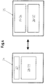
- Fig. 4
- ein schematisiertes Blockdiagramm für das Laufzeitverhalten des Steuerungssystems,
- Fig. 5
- ein weiteres schematisiertes Blockschaltbild eines Steuerungssystems für die Palettier-Anlage, inklusive des Palettier-Roboters, und
- Fig. 6
- ein schematisiertes Blockschaltbild zweier SPS-Tasks sowie eines Echtzeitkerns.
- 10
- Steuerungssystem
- 11
- Palettier-Roboter
- 12
- Datenübertragungseinrichtung
- 13
- Steuerungseinrichtung
- 14
- Motoransteuerung
- 15
- I/O-Modul
- 16
- I/O-Modul
- 17
- Greifer
- 18
- I/O-Modul
- 19
- Zuführtisch
- 20
- Kippeinrichtung
- 21
- I/O-Modul
- 22
- I/O-Modul
- 23
- Industrie-Personalcomputer
- 24
- Steuerungskomponente
- 25
- Steuerungskomponente
- 26
- IRL-Interpreter
- 27
- Bedienpult-Modul
- 28
- Positionierungs-Modul
- 29
- Modul
- 30
- SPS-Compiler
- 31
- Datei
- 32
- Datei
- 33
- Datei
- 34
- SPS-Task
- 35
- SPS-Modul
- 36
- Positionierungs-Task
- 37
- Modul
- 38
- Datei
- 39
- Modul
- 40
- Steuerungskomponente
- 41
- Palettiersystem
- 42
- Datei
- 43
- Datenspeicher
- 44
- Steuerungsmodul
- 44a
- Bewegungsvorbereitung
- 44b
- Benutzeroberfläche
- 44c
- SPS-Modul
- 46
- standardisierte Software-Schnittstelle
- 47
- Visualisierungsmodul bzw. Bedienpult
- 48
- Echtzeitkern
- 49
- Linearverfahren
- 50
- PTP-Verfahren
- 51
- anderes Verfahren
- 52
- SPS-Task
- 53
- SPS-Task
- 54
- Anlagensteuerung
- 55
- Echtzeitmodul
Claims (12)
- Steuerungssystem für Roboter, insbesondere für Palettieranlagen mit Robotern, wobei ein Roboter (11) und Palettieranlagenkomponenten (17, 19, 20) über eine Datenübertragungseinrichtung (12) mit einer Steuerungseinrichtung (13) verbunden sind, dadurch gekennzeichnet, daß die Steuerungseinrichtung (13) als ein Microprozessorsystem, insbesondere als ein Industrie-Personalcomputer (23), ausgebildet ist, wobei das Microprozessorsystem sämtliche Steuerungseinrichtungs-Funktionen, insbesondere Funktionen einer Roboterablaufsteuerung, einer SPS und eines Bedienpults, zur Steuerung der Palettieranlage realisiert.
- Steuerungssystem nach Anspruch 1, dadurch gekennzeichnet, daß Funktionen der Roboterablaufsteuerung und des Bedienpults gemeinsam als eine erste Steuerungskomponente (24) auf dem Microprozessorsystem realisiert sind.
- Steuerungssystem nach Anspruch 1 oder 2, dadurch gekennzeichnet, daß Funktionen der SPS als Teil einer zweiten Steuerungskomponente (25) auf dem Microprozessorsystem realisiert sind.
- Steuerungssystem nach einem der Ansprüche 1 bis 3, dadurch gekennzeichnet, daß die erste Steuerungskomponente (24) und die zweite Steuerungskomponente (25) auf dem Microprozessorsystem unabhängig voneinander realisiert sind.
- Steuerungssystem nach einem der Ansprüche 1 bis 4, dadurch gekennzeichnet, daß die zweite Steuerungskomponente (25) in einem Echtzeittakt realisiert ist.
- Steuerungssystem nach einem der Ansprüche 1 bis 5, dadurch gekennzeichnet, daß die erste Steuerungskomponente (24) über Schnittstellen mit der zweiten Steuerungskomponente (25) kommuniziert, wobei die zweite Steuerungskomponente (25) echtzeitfähige Steuerungsbefehle für den Roboter (11) generiert.
- Steuerungssystem nach einem der Ansprüche 1 bis 6, dadurch gekennzeichnet, daß die erste Steuerungskomponente (24) und die zweite Steuerungskomponente (25) über Dateien (31, 32, 33, 38) an die zu steuernde Palettieranlage mit Roboter (11) anpaßbar sind.
- Steuerungssystem nach einem der Ansprüche 1 bis 7, gekennzeichnet durch eine dritte Steuerungskomponente (40), wobei die dritte Steuerungskomponente (40) über eine Schnittstelle mit der ersten Steuerungskomponente (24) kommuniziert.
- Steuerungssystem nach einem der Ansprüche 1 bis 8, dadurch gekennzeichnet, daß die erste Steuerungskomponente (24) über die dritte Steuerungskomponente (40) an die von der zu steuernden Palettieranlage handzuhabenden Packmuster oder dergleichen anpaßbar ist.
- Steuerungssystem nach Anspruch 1 oder einem der Ansprüche 3 bis 9, dadurch gekennzeichnet, daß Funktionen der Roboterablaufsteuerung als erste Steuerungskomponente (24) auf dem Microprozessorsystem und Funktionen des Bedienpults als vierte Steuerungskomponente (47) realisiert sind.
- Steuerungssystem nach einem der Ansprüche 1 bis 10, dadurch gekennzeichnet, daß alle Steuerungskomponenten (24, 25, 40, 47) unabhängig voneinander realisiert sind.
- Steuerungssystem nach einem der Ansprüche 1 bis 11, dadurch gekennzeichnet, daß es eine standardisierte Software-Schnittstelle (46) aufweist.
Applications Claiming Priority (2)
| Application Number | Priority Date | Filing Date | Title |
|---|---|---|---|
| DE19740775A DE19740775A1 (de) | 1997-09-17 | 1997-09-17 | Steuerungssystem für insbesondere Palettieranlagen mit Robotern |
| DE19740775 | 1997-09-17 |
Publications (3)
| Publication Number | Publication Date |
|---|---|
| EP0903654A2 true EP0903654A2 (de) | 1999-03-24 |
| EP0903654A3 EP0903654A3 (de) | 2000-08-30 |
| EP0903654B1 EP0903654B1 (de) | 2004-11-24 |
Family
ID=7842564
Family Applications (1)
| Application Number | Title | Priority Date | Filing Date |
|---|---|---|---|
| EP98116930A Expired - Lifetime EP0903654B1 (de) | 1997-09-17 | 1998-09-08 | Steuerungssystem für eine Palettieranlage |
Country Status (6)
| Country | Link |
|---|---|
| EP (1) | EP0903654B1 (de) |
| JP (1) | JPH11165285A (de) |
| KR (1) | KR19990029847A (de) |
| CN (1) | CN1070103C (de) |
| BR (1) | BR9803464A (de) |
| DE (2) | DE19740775A1 (de) |
Cited By (4)
| Publication number | Priority date | Publication date | Assignee | Title |
|---|---|---|---|---|
| WO2003023527A3 (de) * | 2001-09-12 | 2003-12-24 | Rexroth Indramat Gmbh | Verfahren zur steuerung und/oder regelung von industriellen prozessen |
| EP1400882A3 (de) * | 2002-09-20 | 2005-08-24 | Siemens Aktiengesellschaft | Vorrichtung zur Automatisierung und/oder Steuerung von Werkzeug-oder Produktionsmaschinen |
| US7035710B2 (en) | 2003-02-06 | 2006-04-25 | Siemens Aktiengesellschaft | Device for automating and/or controlling of machine tools or production machines |
| EP1906284A1 (de) * | 2006-09-28 | 2008-04-02 | Abb Ab | Steuervorrichtung zur Steuerung eines Industrieroboters |
Families Citing this family (9)
| Publication number | Priority date | Publication date | Assignee | Title |
|---|---|---|---|---|
| DE10021838A1 (de) * | 2000-05-05 | 2001-11-08 | Focke & Co | Vorrichtung zum Herstellen von Produkten und Verfahren zum Steuern einer derartigen Vorrichtung |
| DE10307332A1 (de) * | 2003-02-17 | 2004-09-02 | Siemens Ag | Elektrisches Automatisierungsgerät und Verfahren zum Einstellen der Funktionen des Elektrischen Automatisierungsgerätes |
| JP2007038326A (ja) * | 2005-08-01 | 2007-02-15 | Toyota Motor Corp | ロボット制御システム |
| KR100919115B1 (ko) * | 2007-10-31 | 2009-09-25 | 한국기계연구원 | 듀얼 암 로봇 제어장치 |
| EP2711142B1 (de) * | 2012-09-20 | 2014-09-17 | Comau S.p.A. | Industrieroboter mit am Roboter verteilten Motortreibern |
| CN103358309B (zh) * | 2013-07-12 | 2016-06-08 | 杭州金人自动控制设备有限公司 | 一种基于以太网的机械手运动控制系统 |
| RU2578759C2 (ru) * | 2013-09-06 | 2016-03-27 | Общество С Ограниченной Ответственностью "Кибернетические Технологии" | Устройство управления в киберфизических системах, преимущественно для управления мобильными роботами и/или беспилотными летательными аппаратами |
| CN104786221B (zh) * | 2015-04-13 | 2016-12-07 | 浙江工业大学 | 一种基于以太网的开放式机械手控制方法 |
| KR101969727B1 (ko) * | 2017-10-24 | 2019-04-17 | 주식회사 로보스타 | 다관절 로봇을 조작하기 위한 장치 및 그 방법 |
Family Cites Families (15)
| Publication number | Priority date | Publication date | Assignee | Title |
|---|---|---|---|---|
| JPS60198605A (ja) * | 1984-03-22 | 1985-10-08 | Fanuc Ltd | アナログ入力制御方式 |
| NL8502525A (nl) * | 1985-09-16 | 1987-04-16 | Groot R Holding Laag Zuthem Bv | Manipulator. |
| US5032975A (en) * | 1987-08-07 | 1991-07-16 | Canon Kabushiki Kaisha | Controller for automatic assembling apparatus |
| JP2518331B2 (ja) * | 1988-01-11 | 1996-07-24 | トヨタ自動車株式会社 | ロボット動作時間の分析装置 |
| US5193973A (en) * | 1988-12-31 | 1993-03-16 | System Gmbh | Palletizing system |
| JPH04229308A (ja) * | 1990-12-27 | 1992-08-18 | Fanuc Ltd | パレタイジングの教示方法 |
| JPH04324698A (ja) * | 1991-04-24 | 1992-11-13 | Fujitsu Ltd | 異形smd搭載機 |
| US5636966A (en) * | 1992-10-07 | 1997-06-10 | Hk Systems, Inc. | Case picking system |
| JP2574983B2 (ja) * | 1993-04-06 | 1997-01-22 | 本田技研工業株式会社 | マルチタスク制御システム |
| JPH0724665A (ja) * | 1993-07-05 | 1995-01-27 | Yamatake Honeywell Co Ltd | 自動組立装置 |
| JPH0811074A (ja) * | 1994-06-29 | 1996-01-16 | Fanuc Ltd | ロボットシステム |
| JPH08179807A (ja) * | 1994-12-22 | 1996-07-12 | Toppan Printing Co Ltd | 製造ライン管理システム |
| JPH0964599A (ja) * | 1995-08-22 | 1997-03-07 | Ricoh Co Ltd | 多品種製造装置のデータ管理システム |
| JP3536547B2 (ja) * | 1995-09-19 | 2004-06-14 | 三菱電機株式会社 | モニタシステムおよびモニタ方法 |
| WO1997012304A1 (en) * | 1995-09-26 | 1997-04-03 | Omron Corporation | Method and apparatus for information processing |
-
1997
- 1997-09-17 DE DE19740775A patent/DE19740775A1/de not_active Withdrawn
-
1998
- 1998-09-08 DE DE59812295T patent/DE59812295D1/de not_active Expired - Lifetime
- 1998-09-08 EP EP98116930A patent/EP0903654B1/de not_active Expired - Lifetime
- 1998-09-16 BR BR9803464-2A patent/BR9803464A/pt not_active Application Discontinuation
- 1998-09-16 KR KR1019980038230A patent/KR19990029847A/ko not_active Withdrawn
- 1998-09-17 JP JP10263582A patent/JPH11165285A/ja active Pending
- 1998-09-17 CN CN98119278A patent/CN1070103C/zh not_active Expired - Fee Related
Cited By (6)
| Publication number | Priority date | Publication date | Assignee | Title |
|---|---|---|---|---|
| WO2003023527A3 (de) * | 2001-09-12 | 2003-12-24 | Rexroth Indramat Gmbh | Verfahren zur steuerung und/oder regelung von industriellen prozessen |
| US7228185B2 (en) | 2001-09-12 | 2007-06-05 | Rexroth Indramat Gmbh | Method for controlling and/or regulating industrial processes |
| EP1400882A3 (de) * | 2002-09-20 | 2005-08-24 | Siemens Aktiengesellschaft | Vorrichtung zur Automatisierung und/oder Steuerung von Werkzeug-oder Produktionsmaschinen |
| US7035710B2 (en) | 2003-02-06 | 2006-04-25 | Siemens Aktiengesellschaft | Device for automating and/or controlling of machine tools or production machines |
| EP1906284A1 (de) * | 2006-09-28 | 2008-04-02 | Abb Ab | Steuervorrichtung zur Steuerung eines Industrieroboters |
| WO2008037567A1 (en) * | 2006-09-28 | 2008-04-03 | Abb Ab | A control device for controlling an industrial robot |
Also Published As
| Publication number | Publication date |
|---|---|
| DE59812295D1 (de) | 2004-12-30 |
| CN1211492A (zh) | 1999-03-24 |
| KR19990029847A (ko) | 1999-04-26 |
| EP0903654B1 (de) | 2004-11-24 |
| JPH11165285A (ja) | 1999-06-22 |
| DE19740775A1 (de) | 1999-03-18 |
| EP0903654A3 (de) | 2000-08-30 |
| BR9803464A (pt) | 1999-11-23 |
| CN1070103C (zh) | 2001-08-29 |
Similar Documents
| Publication | Publication Date | Title |
|---|---|---|
| EP1184759B1 (de) | Flow Chart Programmierung für industrielle Steuerungen, insbesondere Bewegungssteuerungen | |
| EP0875023B1 (de) | Automatisierungsgerät | |
| DE3151752C2 (de) | Verfahren und Anordnung zur Steuerung eines Roboters | |
| DE20004370U1 (de) | Industrielle Produktionsanlage mit WEB-Steuersystem | |
| EP0903654B1 (de) | Steuerungssystem für eine Palettieranlage | |
| DE4411426B4 (de) | Multitask-Steuersystem | |
| DE3806966C2 (de) | ||
| DE4431315A1 (de) | Steuerungsverfahren und Steuerungsvorrichtung für Fabrik-Automatisierungssystem | |
| DE3236320A1 (de) | Vorrichtung zum bewegen eines werkzeugmittelpunktes eines funktionselementes, insbesondere eines roboterarms | |
| WO2002065223A2 (de) | Steuerungs- und überwachungsanlage von maschinen und/oder anlagen mit aktionskomponenten unterschiedlicher aktionsgruppen | |
| EP0553621B1 (de) | Programmierbare Computersteuerung für eine Werkzeugmaschine | |
| DE2338880A1 (de) | Verfahren und vorrichtungen zur steuerung der beweglichen teile einer werkzeugmaschine durch ein numerisches umriss- oder punkt-fuer-punkt-steuerungssystem, wobei zwei teile der maschine unabhaengig voneinander entlang einer gemeinsamen achse bewegt werden koennen | |
| EP0838054B1 (de) | Verfahren und steuereinrichtung für eine graphische steuerung von abläufen in einem netzwerkmanagementsystem | |
| DE10359251A1 (de) | Vorrichtung zur Automatisierung von Werkzeug- oder Produktionsmaschinen | |
| EP1217476A2 (de) | Vorrichtung und Verfahren zur Inbetriebnahme und Diagnose von Steuerungssystemen | |
| DE112021005212T5 (de) | Numerik-Steuersystem und Verfahren zur Steuerung einer Industriemaschine | |
| DE10296995T5 (de) | Verfahren zum Abstimmen und Synchronisieren der Bewegung von Servounterstützten Achsen | |
| EP3132319B1 (de) | Verfahren zum betrieb einer automatisierungsanordnung | |
| DE112021005374T5 (de) | Numerik-Steuervorrichtung und Numerik-Steuersystem | |
| DE3500806C2 (de) | Steuerung für einen Industrie-Schweißroboter | |
| DE10038441B4 (de) | "Flow Chart Programmierung für industrielle Steuerungen, insbesondere Bewegungssteuerungen" | |
| EP1183577B1 (de) | Verfahren zur erzeugung eines steuerbausteins und steuerbaustein | |
| DE10038439B4 (de) | Vorrichtung, zumindest umfassend ein Computersystem und eine industrielle Steuerung, für das Debuggen von Programmen für industrielle Steuerungen | |
| EP1393139B1 (de) | Programmierwerkzeug und verfahren zur erstellung von programmen, insbesondere der automatisierungstechnik | |
| DE3706275C2 (de) |
Legal Events
| Date | Code | Title | Description |
|---|---|---|---|
| PUAI | Public reference made under article 153(3) epc to a published international application that has entered the european phase |
Free format text: ORIGINAL CODE: 0009012 |
|
| AK | Designated contracting states |
Kind code of ref document: A2 Designated state(s): CH DE FR GB IT LI NL |
|
| AX | Request for extension of the european patent |
Free format text: AL;LT;LV;MK;RO;SI |
|
| PUAL | Search report despatched |
Free format text: ORIGINAL CODE: 0009013 |
|
| AK | Designated contracting states |
Kind code of ref document: A3 Designated state(s): AT BE CH CY DE DK ES FI FR GB GR IE IT LI LU MC NL PT SE |
|
| AX | Request for extension of the european patent |
Free format text: AL;LT;LV;MK;RO;SI |
|
| AKX | Designation fees paid | ||
| 17P | Request for examination filed |
Effective date: 20001124 |
|
| RBV | Designated contracting states (corrected) |
Designated state(s): CH DE FR GB IT LI NL |
|
| 17Q | First examination report despatched |
Effective date: 20030702 |
|
| GRAP | Despatch of communication of intention to grant a patent |
Free format text: ORIGINAL CODE: EPIDOSNIGR1 |
|
| RTI1 | Title (correction) |
Free format text: CONTROL SYSTEM FOR A PALLETISATION INSTALLATION |
|
| RTI1 | Title (correction) |
Free format text: CONTROL SYSTEM FOR A PALLETISATION INSTALLATION |
|
| GRAS | Grant fee paid |
Free format text: ORIGINAL CODE: EPIDOSNIGR3 |
|
| GRAA | (expected) grant |
Free format text: ORIGINAL CODE: 0009210 |
|
| RAP1 | Party data changed (applicant data changed or rights of an application transferred) |
Owner name: FOCKE & CO. (GMBH & CO. KG) |
|
| AK | Designated contracting states |
Kind code of ref document: B1 Designated state(s): CH DE FR GB IT LI NL |
|
| REG | Reference to a national code |
Ref country code: GB Ref legal event code: FG4D Free format text: NOT ENGLISH |
|
| REG | Reference to a national code |
Ref country code: CH Ref legal event code: EP |
|
| REF | Corresponds to: |
Ref document number: 59812295 Country of ref document: DE Date of ref document: 20041230 Kind code of ref document: P |
|
| REG | Reference to a national code |
Ref country code: CH Ref legal event code: NV Representative=s name: R. A. EGLI & CO. PATENTANWAELTE |
|
| GBT | Gb: translation of ep patent filed (gb section 77(6)(a)/1977) |
Effective date: 20041214 |
|
| PLBE | No opposition filed within time limit |
Free format text: ORIGINAL CODE: 0009261 |
|
| STAA | Information on the status of an ep patent application or granted ep patent |
Free format text: STATUS: NO OPPOSITION FILED WITHIN TIME LIMIT |
|
| 26N | No opposition filed |
Effective date: 20050825 |
|
| ET | Fr: translation filed | ||
| PGFP | Annual fee paid to national office [announced via postgrant information from national office to epo] |
Ref country code: CH Payment date: 20110913 Year of fee payment: 14 |
|
| PGFP | Annual fee paid to national office [announced via postgrant information from national office to epo] |
Ref country code: FR Payment date: 20110922 Year of fee payment: 14 |
|
| PGFP | Annual fee paid to national office [announced via postgrant information from national office to epo] |
Ref country code: NL Payment date: 20110922 Year of fee payment: 14 |
|
| REG | Reference to a national code |
Ref country code: NL Ref legal event code: V1 Effective date: 20130401 |
|
| REG | Reference to a national code |
Ref country code: CH Ref legal event code: PL |
|
| REG | Reference to a national code |
Ref country code: FR Ref legal event code: ST Effective date: 20130531 |
|
| PG25 | Lapsed in a contracting state [announced via postgrant information from national office to epo] |
Ref country code: CH Free format text: LAPSE BECAUSE OF NON-PAYMENT OF DUE FEES Effective date: 20120930 Ref country code: LI Free format text: LAPSE BECAUSE OF NON-PAYMENT OF DUE FEES Effective date: 20120930 |
|
| PG25 | Lapsed in a contracting state [announced via postgrant information from national office to epo] |
Ref country code: FR Free format text: LAPSE BECAUSE OF NON-PAYMENT OF DUE FEES Effective date: 20121001 Ref country code: NL Free format text: LAPSE BECAUSE OF NON-PAYMENT OF DUE FEES Effective date: 20130401 |
|
| PGFP | Annual fee paid to national office [announced via postgrant information from national office to epo] |
Ref country code: GB Payment date: 20140903 Year of fee payment: 17 |
|
| PGFP | Annual fee paid to national office [announced via postgrant information from national office to epo] |
Ref country code: IT Payment date: 20140915 Year of fee payment: 17 |
|
| PGFP | Annual fee paid to national office [announced via postgrant information from national office to epo] |
Ref country code: DE Payment date: 20140930 Year of fee payment: 17 |
|
| REG | Reference to a national code |
Ref country code: DE Ref legal event code: R119 Ref document number: 59812295 Country of ref document: DE |
|
| PG25 | Lapsed in a contracting state [announced via postgrant information from national office to epo] |
Ref country code: IT Free format text: LAPSE BECAUSE OF NON-PAYMENT OF DUE FEES Effective date: 20150908 |
|
| GBPC | Gb: european patent ceased through non-payment of renewal fee |
Effective date: 20150908 |
|
| PG25 | Lapsed in a contracting state [announced via postgrant information from national office to epo] |
Ref country code: DE Free format text: LAPSE BECAUSE OF NON-PAYMENT OF DUE FEES Effective date: 20160401 Ref country code: GB Free format text: LAPSE BECAUSE OF NON-PAYMENT OF DUE FEES Effective date: 20150908 |