EP0903540A1 - Brûleur pour la mise en oeuvre d'un générateur de chaleur - Google Patents
Brûleur pour la mise en oeuvre d'un générateur de chaleur Download PDFInfo
- Publication number
- EP0903540A1 EP0903540A1 EP97810687A EP97810687A EP0903540A1 EP 0903540 A1 EP0903540 A1 EP 0903540A1 EP 97810687 A EP97810687 A EP 97810687A EP 97810687 A EP97810687 A EP 97810687A EP 0903540 A1 EP0903540 A1 EP 0903540A1
- Authority
- EP
- European Patent Office
- Prior art keywords
- burner
- flow
- burner according
- fuel
- swirl generator
- Prior art date
- Legal status (The legal status is an assumption and is not a legal conclusion. Google has not performed a legal analysis and makes no representation as to the accuracy of the status listed.)
- Granted
Links
Images


Classifications
-
- F—MECHANICAL ENGINEERING; LIGHTING; HEATING; WEAPONS; BLASTING
- F23—COMBUSTION APPARATUS; COMBUSTION PROCESSES
- F23C—METHODS OR APPARATUS FOR COMBUSTION USING FLUID FUEL OR SOLID FUEL SUSPENDED IN A CARRIER GAS OR AIR
- F23C7/00—Combustion apparatus characterised by arrangements for air supply
- F23C7/002—Combustion apparatus characterised by arrangements for air supply the air being submitted to a rotary or spinning motion
-
- F—MECHANICAL ENGINEERING; LIGHTING; HEATING; WEAPONS; BLASTING
- F23—COMBUSTION APPARATUS; COMBUSTION PROCESSES
- F23D—BURNERS
- F23D11/00—Burners using a direct spraying action of liquid droplets or vaporised liquid into the combustion space
- F23D11/36—Details
- F23D11/40—Mixing tubes; Burner heads
- F23D11/402—Mixing chambers downstream of the nozzle
-
- F—MECHANICAL ENGINEERING; LIGHTING; HEATING; WEAPONS; BLASTING
- F23—COMBUSTION APPARATUS; COMBUSTION PROCESSES
- F23D—BURNERS
- F23D17/00—Burners for combustion simultaneously or alternately of gaseous or liquid or pulverulent fuel
- F23D17/002—Burners for combustion simultaneously or alternately of gaseous or liquid or pulverulent fuel gaseous or liquid fuel
-
- F—MECHANICAL ENGINEERING; LIGHTING; HEATING; WEAPONS; BLASTING
- F23—COMBUSTION APPARATUS; COMBUSTION PROCESSES
- F23C—METHODS OR APPARATUS FOR COMBUSTION USING FLUID FUEL OR SOLID FUEL SUSPENDED IN A CARRIER GAS OR AIR
- F23C2900/00—Special features of, or arrangements for combustion apparatus using fluid fuels or solid fuels suspended in air; Combustion processes therefor
- F23C2900/07002—Premix burners with air inlet slots obtained between offset curved wall surfaces, e.g. double cone burners
-
- F—MECHANICAL ENGINEERING; LIGHTING; HEATING; WEAPONS; BLASTING
- F23—COMBUSTION APPARATUS; COMBUSTION PROCESSES
- F23D—BURNERS
- F23D2210/00—Noise abatement
Definitions
- the invention relates to a burner for operating a heat generator according to Preamble of claim 1.
- a burner which is made on the inflow side a swirl generator, the flow formed therein seamlessly into one Mixing section is transferred. This is done using one at the beginning of the mixing section flow geometry formed for this purpose, which consists of transition channels exists, which is sectoral, according to the number of acting partial bodies of the swirl generator, grasp the end face of the mixing section and in the direction of flow twisted. On the outflow side of these transition channels Mixing section on a number of filming holes, which increase the Ensure flow velocity along the pipe wall. Then follows a combustion chamber, the transition between the mixing section and the Combustion chamber is formed by a cross-sectional jump, in the plane of which forms a backflow zone or backflow bubble.
- the swirl strength in the swirl generator is selected so that the bursting of the Vortex does not occur within the mixing section, but further downstream, as above executed in the area of the cross-sectional jump.
- the length of the mixing section is like this dimensioned to ensure sufficient mix quality for all types of fuel is.
- the invention seeks to remedy this.
- the invention as set out in the claims is characterized, the task is based on a burner of the type mentioned To propose kind of precautions which would strengthen the flame stability and an adaptation of the flame to the given combustion chamber geometry effect without diminishing in any way the other advantages of this burner.
- the one acting on the head and the swirl generator of the burner belonging fuel nozzle which is preferably on the axis of the swirl generator or the burner and which is usually with a liquid Fuel is fed, surrounded by an annular spaced jacket, in which holes are made in the circumferential direction, through which a Air volume flows around the fuel nozzle.
- additional injectors which are preferably with a gaseous Fuel operated. A small amount of fuel is generated by this Injectors injected into the air volume for flushing around the fuel nozzle, in such a way that the center of the burner flow, which is important for the stability of the flame, always is supplied to the right extent.
- Another advantage of the invention can be seen in the fact that the purge air through the above Openings in the area of the fuel nozzle wetting the inner wall of the conical swirl generator prevented by the injected liquid fuel.
- Fig. 1 shows the overall structure of a burner.
- a swirl generator is 100 effective, the design of which is shown in more detail in the following FIGS. 3-6 and is described.
- This swirl generator 100 is a conical one Formation that is tangential several times from a tangentially flowing combustion air flow 115 is applied.
- the current that forms here is based on a transition geometry provided downstream of the swirl generator 100 transitioned seamlessly into a transition piece 200 such that there are none Detachment areas can occur.
- the configuration of this transition geometry is described in more detail in Fig. 6.
- This transition piece 200 is on the outflow side the transition geometry extended by a mixing tube 20, both Parts form the actual mixing section 220.
- the mixing section 220 consist of a single piece, i.e.
- Transition piece 200 and mixing tube 20 created from two parts these are connected by a bushing ring 10, the same bushing ring 10 on the head side serves as anchoring surface for the swirl generator 100.
- Such a bushing ring 10 also has the advantage that different mixing tubes are used can.
- the actual combustion chamber is located on the outflow side of the mixing tube 20 30, which is only symbolized here by a flame tube.
- the Mixing section 220 largely fulfills the task that is downstream of the swirl generator 100 a defined route is provided, in which a perfect premix of different types of fuel can be achieved.
- This mixing section so ostensibly the mixing tube 20, furthermore enables lossless flow guidance, so that it is also in operative connection with the transition geometry initially cannot form a backflow zone or backflow bubble, which means that Length of the mixing section 220 influences the quality of the mixture for all types of fuel can be exercised.
- This mixing section 220 has yet another property, which consists of the fact that the axial velocity profile is in it has a pronounced maximum on the axis, so that the Flame from the combustion chamber is not possible. However, it is true that at in such a configuration, this axial velocity drops towards the wall.
- the mixing tube 20 in Flow and circumferential direction with a number of regular or irregular distributed holes 21 of different cross sections and directions, through which an amount of air flows into the interior of the mixing tube 20, and along the wall in the sense of a filming an increase in the flow rate induce.
- These holes 21 can also be designed in such a way that the inner wall of the mixing tube 20 at least additionally an effusion cooling sets.
- Another possibility is to increase the speed of the mixture To achieve within the mixing tube 20 is that Flow cross-section on the downstream side of the transition channels 201, which already have the called transition geometry form, undergoes a narrowing, whereby the entire speed level within the mixing tube 20 is raised.
- these bores 21 run at an acute angle with respect to the Burner axis 60.
- the outlet corresponds to the transition channels 201 the narrowest flow cross-section of the mixing tube 20.
- the transition channels mentioned 201 accordingly bridge the respective cross-sectional difference, without negatively influencing the flow formed. If the chosen one Precautions when guiding the pipe flow 40 along the mixing pipe 20 causes intolerable pressure loss, this can be remedied, by a diffuser, not shown in the figure, at the end of this mixing tube is provided.
- a combustion chamber then closes at the end of the mixing tube 20 30 on, between the two flow cross-sections by a Burner front 70 formed cross-sectional jump is present.
- FIG. 2 shows a schematic view of the burner according to FIG. 1, in particular here on the washing around a centrally arranged fuel nozzle 103 and the effect of fuel injectors 170 is pointed out.
- the fuel nozzle 103 is covered with a spaced ring 190, in which a number of holes 161 are provided in the circumferential direction, through which an amount of air 160 flows into an annular chamber 180 and there the Around the fuel lance. These holes 161 are oblique laid out in front such that an adequate axial component on the Burner axis 60 is created.
- Fuel injectors 170 are provided, which preferably a certain amount enter a gaseous fuel into the respective air volume 160, such that there is a uniform fuel concentration in the mixing tube 20 150 sets over the flow cross-section, as the representation in the figure symbolize want. Exactly this uniform fuel concentration 150, in particular the strong concentration on the burner axis 60 ensures that a Stabilization of the flame front at the exit of the burner sets, with which emerging Combustion chamber pulsations can be avoided.
- FIG. 4 is used at the same time as FIG. 3. The following will 3 in the description of FIG.
- the first part of the burner according to FIG. 1 forms the swirl generator shown in FIG. 3 100.
- This consists of two high conical partial bodies 101, 102 which are nested staggered.
- the number of conical part bodies can of course be greater than two, as shown in Figures 5 and 6; this depends on, as will be explained in more detail below the operating mode of the entire burner. It is with certain operating constellations not excluded, a swirl generator consisting of a single spiral to provide.
- the offset of the respective central axis or longitudinal symmetry axes 101b, 102b (see FIG. 4) of the tapered partial bodies 101, 102 to one another creates one on each of the neighboring walls in a mirror-image arrangement tangential channel, i.e.
- the conical shape of the partial bodies 101, 102 shown in Flow direction has a certain fixed angle. Of course, ever after operational use, the partial bodies 101, 102 can increase in the direction of flow or have decreasing cone inclination, similar to a trumpet resp. Tulip. The last two forms are not included in the drawing as they are for the expert can be easily understood.
- the two conical partial bodies 101, 102 each have a cylindrical annular starting part 101a. In the area this cylindrical starting part is the fuel nozzle already mentioned in FIG. 2 103 housed, which preferably with a liquid fuel 112 is operated.
- the injection 104 of this fuel 112 coincides with that narrowest cross-section of the conical cavity formed by the conical partial bodies 101, 102 114 together.
- the injection capacity and the type of this fuel nozzle 103 depends on the given parameters of the respective burner.
- the tapered partial bodies 101, 102 further each have a fuel line 108, 109, which are arranged along the tangential air inlet slots 119, 120 and are provided with injection openings 117, through which preferably a gaseous fuel 113 is injected into the combustion air 115 flowing through there is how the arrows 116 symbolize this.
- These fuel lines 108, 109 are preferably at the latest at the end of the tangential inflow Entry into the cone cavity 114, arranged, this for an optimal Obtain air / fuel mixture.
- fuel 112 is normally a liquid Fuel, forming a mixture with another medium, for example with a recirculated flue gas, is easily possible. That fuel 112 is at a preferably very acute angle in the cone cavity 114 injected. A conical fuel spray thus forms from the fuel nozzle 103 105, the rotating combustion air flowing in tangentially 115 enclosed and dismantled. The concentration is then in the axial direction of the injected fuel 112 continuously through the inflowing combustion air 115 degraded to mix in the direction of evaporation.
- the construction of the swirl generator 100 is furthermore excellently suitable, the size of the tangential Air inlet slots 119, 120 to change, so without changing the overall length of the swirl generator 100 covers a relatively large operational bandwidth can be.
- the partial bodies 101, 102 are also in another Plane displaceable relative to one another, which even provides for an overlap thereof can be. It is also possible to pass through the partial bodies 101, 102 to interleave a counter-rotating movement in a spiral. Consequently it is possible to change the shape, size and configuration of the tangential air inlet slots 119, 120 to vary as desired, with which the swirl generator 100 without change its overall length can be used universally.
- FIG. 4 shows, among other things, the geometric configuration of optional ones Baffles 121a, 121b. They have a flow initiation function these, according to their length, the respective end of the tapered partial body 101, 102 extend in the direction of flow towards the combustion air 115.
- the channeling of the combustion air 115 into the cone cavity 114 can be done by Open or close the guide plates 121a, 121b by one in the area of the entrance of this channel in the cone cavity 114 pivot point 123 optimized this is particularly necessary if the original gap size of the tangential air inlet slots 119, 120 should be changed dynamically, for example to change the speed of the combustion air 115 to reach.
- these dynamic arrangements can also be static can be provided by using a fixed component as required form the tapered partial bodies 101, 102.
- the swirl generator 100 now consists of four partial bodies 130, 131, 132, 133 is constructed.
- the associated longitudinal symmetry axes for each sub-body are marked with the letter a.
- This configuration can be said that they are due to the lower twist strength generated with it and in combination with a correspondingly enlarged slot width is suitable for the bursting of the vortex flow on the downstream side of the swirl generator To prevent the mixing tube, so that the mixing tube best fulfills its intended role can meet.
- FIG. 6 differs from FIG. 5 in that the partial bodies 140, 141, 142, 143 have a blade profile shape which is used to provide a certain Flow is provided. Otherwise the mode of operation of the swirl generator is remained the same.
- the admixture of fuel 116 in the combustion air flow 115 happens from the inside of the blade profiles, i.e. the fuel line 108 is now integrated in the individual blades. They are here too Longitudinal axes of symmetry to the individual partial bodies marked with the letter a.
- the transition geometry is corresponding for a swirl generator 100 with four partial bodies 5 or 6, built. Accordingly, the transition geometry points as Natural extension of the upstream part of the four transition channels 201 on, whereby the conical quarter area of the partial bodies is extended until it cuts the wall of the mixing tube.
- the same considerations also apply if the swirl generator is based on a principle other than that described under FIG. 3, is constructed.
- the downward surface of the individual Transition channels 201 have a spiral in the flow direction Form, which describes a crescent-shaped course, according to the The fact that in the present case the flow cross section of the transition piece 200 flared in the direction of flow.
- the twist angle of the transition channels 201 in the flow direction is selected so that the pipe flow then up to for the cross-sectional jump at the combustion chamber inlet there is still a sufficiently large distance remains to achieve a perfect premix with the injected fuel. Furthermore, the measures mentioned above also increase the Axial speed on the mixing tube wall downstream of the swirl generator. The transition geometry and the measures in the area of the mixing tube cause one significant increase in the axial speed profile to the center of the mixing tube so that the danger of early ignition is decisively counteracted.
- the flow cross-section of the tube 20 receives a transition radius in this area R, the size of which basically depends on the flow within the Tube 20 depends.
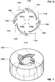
- This radius R is chosen so that the flow adjusts to the Puts on the wall and so the swirl number increases sharply. It can be quantified Define the size of the radius R so that it is> 10% of the inside diameter d of the tube is 20. Compared to a flow without a radius increases now the backflow bladder 50 tremendous.
- This radius R extends to the exit plane of the tube 20, the angle ⁇ between the beginning and end of the curvature ⁇ 90 ° is.
- the tear-off edge A ins runs along one leg of the angle ⁇ Interior of the tube 20 and thus forms a demolition step S compared to the front Point of the tear-off edge A, the depth of which is> 3 mm.
- the here running parallel to the exit plane of the tube 20 edge using a curved Are brought back to the exit level.
- the angle ⁇ ' the between the tangent of the tear-off edge A and perpendicular to the exit plane of the pipe 20 is the same size as the angle ⁇ .
Landscapes
- Engineering & Computer Science (AREA)
- Chemical & Material Sciences (AREA)
- Combustion & Propulsion (AREA)
- Mechanical Engineering (AREA)
- General Engineering & Computer Science (AREA)
- Spray-Type Burners (AREA)
- Pressure-Spray And Ultrasonic-Wave- Spray Burners (AREA)
Priority Applications (5)
| Application Number | Priority Date | Filing Date | Title |
|---|---|---|---|
| DE59709791T DE59709791D1 (de) | 1997-09-19 | 1997-09-19 | Brenner für den Betrieb eines Wärmeerzeugers |
| EP97810687A EP0903540B1 (fr) | 1997-09-19 | 1997-09-19 | Brûleur pour la mise en oeuvre d'un générateur de chaleur |
| US09/153,269 US5944511A (en) | 1997-09-19 | 1998-09-14 | Burner for operating a heat generator |
| CNB981192939A CN1143077C (zh) | 1997-09-19 | 1998-09-18 | 用于运行热发生器的燃烧器 |
| JP26681698A JP4155635B2 (ja) | 1997-09-19 | 1998-09-21 | 熱発生器を稼働させるためのバーナ |
Applications Claiming Priority (1)
| Application Number | Priority Date | Filing Date | Title |
|---|---|---|---|
| EP97810687A EP0903540B1 (fr) | 1997-09-19 | 1997-09-19 | Brûleur pour la mise en oeuvre d'un générateur de chaleur |
Publications (2)
| Publication Number | Publication Date |
|---|---|
| EP0903540A1 true EP0903540A1 (fr) | 1999-03-24 |
| EP0903540B1 EP0903540B1 (fr) | 2003-04-09 |
Family
ID=8230395
Family Applications (1)
| Application Number | Title | Priority Date | Filing Date |
|---|---|---|---|
| EP97810687A Expired - Lifetime EP0903540B1 (fr) | 1997-09-19 | 1997-09-19 | Brûleur pour la mise en oeuvre d'un générateur de chaleur |
Country Status (5)
| Country | Link |
|---|---|
| US (1) | US5944511A (fr) |
| EP (1) | EP0903540B1 (fr) |
| JP (1) | JP4155635B2 (fr) |
| CN (1) | CN1143077C (fr) |
| DE (1) | DE59709791D1 (fr) |
Families Citing this family (11)
| Publication number | Priority date | Publication date | Assignee | Title |
|---|---|---|---|---|
| ATE244380T1 (de) * | 1997-11-21 | 2003-07-15 | Alstom | Brenner für den betrieb eines wärmeerzeugers |
| ATE237101T1 (de) * | 1998-01-23 | 2003-04-15 | Alstom Switzerland Ltd | Brenner für den betrieb eines wärmeerzeugers |
| DE19914666B4 (de) * | 1999-03-31 | 2009-08-20 | Alstom | Brenner für einen Wärmeerzeuger |
| WO2001077182A1 (fr) * | 2000-04-07 | 2001-10-18 | Matsushita Electric Industrial Co., Ltd. | Complexe anticorps-porteur, procede de production, methode de controle de la reaction antigene-anticorps par ledit complexe et procede de dosage immunologique |
| US6769903B2 (en) * | 2000-06-15 | 2004-08-03 | Alstom Technology Ltd | Method for operating a burner and burner with stepped premix gas injection |
| DE10051221A1 (de) * | 2000-10-16 | 2002-07-11 | Alstom Switzerland Ltd | Brenner mit gestufter Brennstoff-Eindüsung |
| US20050065136A1 (en) * | 2003-08-13 | 2005-03-24 | Roby Russell R. | Methods and compositions for the treatment of infertility using dilute hormone solutions |
| US20050239757A1 (en) * | 2004-04-21 | 2005-10-27 | Roby Russell R | Hormone treatment of macular degeneration |
| US20060025390A1 (en) * | 2004-07-28 | 2006-02-02 | Roby Russell R | Treatment of hormone allergy and related symptoms and disorders |
| US9441543B2 (en) * | 2012-11-20 | 2016-09-13 | Niigata Power Systems Co., Ltd. | Gas turbine combustor including a premixing chamber having an inner diameter enlarging portion |
| US9261852B2 (en) | 2014-02-27 | 2016-02-16 | Ricoh Company, Ltd. | Acoustic device, and electronic device and image forming apparatus incorporating same |
Citations (6)
| Publication number | Priority date | Publication date | Assignee | Title |
|---|---|---|---|---|
| WO1995023316A1 (fr) * | 1994-02-24 | 1995-08-31 | United Technologies Corporation | Buse d'injection de carburant a entree tangentielle |
| EP0710797A2 (fr) * | 1994-11-05 | 1996-05-08 | Abb Research Ltd. | Procédé et dispositif de mise en oeuvre d'un brûleur à prémélange |
| EP0778445A2 (fr) * | 1995-12-05 | 1997-06-11 | Asea Brown Boveri Ag | Brûleur à prémélange |
| EP0780629A2 (fr) | 1995-12-21 | 1997-06-25 | ABB Research Ltd. | Brûleur pour un générateur de chaleur |
| EP0780630A2 (fr) * | 1995-12-21 | 1997-06-25 | Abb Research Ltd. | Brûleur pour un générateur de chaleur |
| DE19548851A1 (de) * | 1995-12-27 | 1997-07-03 | Asea Brown Boveri | Vormischbrenner |
Family Cites Families (2)
| Publication number | Priority date | Publication date | Assignee | Title |
|---|---|---|---|---|
| DE4435266A1 (de) * | 1994-10-01 | 1996-04-04 | Abb Management Ag | Brenner |
| DE19547914A1 (de) * | 1995-12-21 | 1997-06-26 | Abb Research Ltd | Vormischbrenner für einen Wärmeerzeuger |
-
1997
- 1997-09-19 DE DE59709791T patent/DE59709791D1/de not_active Expired - Lifetime
- 1997-09-19 EP EP97810687A patent/EP0903540B1/fr not_active Expired - Lifetime
-
1998
- 1998-09-14 US US09/153,269 patent/US5944511A/en not_active Expired - Lifetime
- 1998-09-18 CN CNB981192939A patent/CN1143077C/zh not_active Expired - Fee Related
- 1998-09-21 JP JP26681698A patent/JP4155635B2/ja not_active Expired - Fee Related
Patent Citations (6)
| Publication number | Priority date | Publication date | Assignee | Title |
|---|---|---|---|---|
| WO1995023316A1 (fr) * | 1994-02-24 | 1995-08-31 | United Technologies Corporation | Buse d'injection de carburant a entree tangentielle |
| EP0710797A2 (fr) * | 1994-11-05 | 1996-05-08 | Abb Research Ltd. | Procédé et dispositif de mise en oeuvre d'un brûleur à prémélange |
| EP0778445A2 (fr) * | 1995-12-05 | 1997-06-11 | Asea Brown Boveri Ag | Brûleur à prémélange |
| EP0780629A2 (fr) | 1995-12-21 | 1997-06-25 | ABB Research Ltd. | Brûleur pour un générateur de chaleur |
| EP0780630A2 (fr) * | 1995-12-21 | 1997-06-25 | Abb Research Ltd. | Brûleur pour un générateur de chaleur |
| DE19548851A1 (de) * | 1995-12-27 | 1997-07-03 | Asea Brown Boveri | Vormischbrenner |
Also Published As
| Publication number | Publication date |
|---|---|
| EP0903540B1 (fr) | 2003-04-09 |
| JPH11148618A (ja) | 1999-06-02 |
| DE59709791D1 (de) | 2003-05-15 |
| US5944511A (en) | 1999-08-31 |
| JP4155635B2 (ja) | 2008-09-24 |
| CN1143077C (zh) | 2004-03-24 |
| CN1212347A (zh) | 1999-03-31 |
Similar Documents
| Publication | Publication Date | Title |
|---|---|---|
| EP0780629B1 (fr) | Brûleur pour un générateur de chaleur | |
| EP0704657B1 (fr) | Brûleur | |
| EP0780630B1 (fr) | Brûleur pour un générateur de chaleur | |
| EP0918191B1 (fr) | Brûleur pour la mise en oeuvre d'un générateur de chaleur | |
| EP0918190A1 (fr) | Brûleur pour la mise en oeuvre d'un générateur de chaleur | |
| EP0833105B1 (fr) | Brûleur à prémélange | |
| EP0899508B1 (fr) | Brûleur pour un dispositif à chaleur | |
| EP0777081B1 (fr) | Brûleur à prémélange | |
| EP0718561B1 (fr) | Brûleur | |
| EP0797051B1 (fr) | Brûleur pour un générateur de chaleur | |
| DE19757189B4 (de) | Verfahren zum Betrieb eines Brenners eines Wärmeerzeugers | |
| EP0916894B1 (fr) | Brûleur pour la mise en oeuvre d'un générateur de chaleur | |
| EP0994300B1 (fr) | Brûleur pour la conduite d'un générateur de chaleur | |
| EP0909921B1 (fr) | Brûleur pour la mise en oeuvre d'un générateur de chaleur | |
| EP0903540B1 (fr) | Brûleur pour la mise en oeuvre d'un générateur de chaleur | |
| EP0919768B1 (fr) | Brûleur pour la mise en oeuvre d'un générateur de chaleur | |
| EP0751351A1 (fr) | Chambre de combustion | |
| EP0833104B1 (fr) | Brûleur pour le fonctionnement d'une chambre de combustion | |
| DE19537636B4 (de) | Kraftwerksanlage | |
| EP0740108A2 (fr) | Brûleur | |
| EP0913630B1 (fr) | Brûleur pour la mise en oeuvre d'un générateur de chaleur | |
| EP0730121A2 (fr) | Brûleur à prémélange | |
| DE19737998A1 (de) | Brennervorrichtung | |
| DE19914666A1 (de) | Brenner für einen Wärmeerzeuger | |
| DE10042315A1 (de) | Brenner für einen Wärmeerzeuger |
Legal Events
| Date | Code | Title | Description |
|---|---|---|---|
| PUAI | Public reference made under article 153(3) epc to a published international application that has entered the european phase |
Free format text: ORIGINAL CODE: 0009012 |
|
| AK | Designated contracting states |
Kind code of ref document: A1 Designated state(s): DE FR GB IT |
|
| 17P | Request for examination filed |
Effective date: 19990429 |
|
| AKX | Designation fees paid |
Free format text: DE FR GB IT |
|
| RAP1 | Party data changed (applicant data changed or rights of an application transferred) |
Owner name: ALSTOM |
|
| 17Q | First examination report despatched |
Effective date: 20020306 |
|
| GRAH | Despatch of communication of intention to grant a patent |
Free format text: ORIGINAL CODE: EPIDOS IGRA |
|
| RAP1 | Party data changed (applicant data changed or rights of an application transferred) |
Owner name: ALSTOM (SWITZERLAND) LTD |
|
| GRAH | Despatch of communication of intention to grant a patent |
Free format text: ORIGINAL CODE: EPIDOS IGRA |
|
| GRAA | (expected) grant |
Free format text: ORIGINAL CODE: 0009210 |
|
| AK | Designated contracting states |
Designated state(s): DE FR GB IT |
|
| REG | Reference to a national code |
Ref country code: GB Ref legal event code: FG4D Free format text: NOT ENGLISH |
|
| GBT | Gb: translation of ep patent filed (gb section 77(6)(a)/1977) | ||
| ET | Fr: translation filed | ||
| PLBE | No opposition filed within time limit |
Free format text: ORIGINAL CODE: 0009261 |
|
| STAA | Information on the status of an ep patent application or granted ep patent |
Free format text: STATUS: NO OPPOSITION FILED WITHIN TIME LIMIT |
|
| 26N | No opposition filed |
Effective date: 20040112 |
|
| REG | Reference to a national code |
Ref country code: DE Ref legal event code: R082 Ref document number: 59709791 Country of ref document: DE Representative=s name: UWE ROESLER, DE |
|
| REG | Reference to a national code |
Ref country code: GB Ref legal event code: 732E Free format text: REGISTERED BETWEEN 20120802 AND 20120808 |
|
| REG | Reference to a national code |
Ref country code: DE Ref legal event code: R082 Ref document number: 59709791 Country of ref document: DE Representative=s name: ROESLER, UWE, DIPL.-PHYS.UNIV., DE Effective date: 20120713 Ref country code: DE Ref legal event code: R081 Ref document number: 59709791 Country of ref document: DE Owner name: GENERAL ELECTRIC TECHNOLOGY GMBH, CH Free format text: FORMER OWNER: ALSTOM (SWITZERLAND) LTD., BADEN, CH Effective date: 20120713 Ref country code: DE Ref legal event code: R081 Ref document number: 59709791 Country of ref document: DE Owner name: ALSTOM TECHNOLOGY LTD., CH Free format text: FORMER OWNER: ALSTOM (SWITZERLAND) LTD., BADEN, CH Effective date: 20120713 |
|
| REG | Reference to a national code |
Ref country code: FR Ref legal event code: TP Owner name: ALSTOM TECHNOLOGY LTD., CH Effective date: 20120918 |
|
| REG | Reference to a national code |
Ref country code: DE Ref legal event code: R082 Ref document number: 59709791 Country of ref document: DE Representative=s name: ROESLER, UWE, DIPL.-PHYS.UNIV., DE Ref country code: DE Ref legal event code: R081 Ref document number: 59709791 Country of ref document: DE Owner name: GENERAL ELECTRIC TECHNOLOGY GMBH, CH Free format text: FORMER OWNER: ALSTOM TECHNOLOGY LTD., BADEN, CH |
|
| REG | Reference to a national code |
Ref country code: FR Ref legal event code: PLFP Year of fee payment: 20 |
|
| PGFP | Annual fee paid to national office [announced via postgrant information from national office to epo] |
Ref country code: GB Payment date: 20160920 Year of fee payment: 20 Ref country code: DE Payment date: 20160921 Year of fee payment: 20 |
|
| PGFP | Annual fee paid to national office [announced via postgrant information from national office to epo] |
Ref country code: FR Payment date: 20160921 Year of fee payment: 20 |
|
| REG | Reference to a national code |
Ref country code: FR Ref legal event code: CD Owner name: ALSTOM TECHNOLOGY LTD, CH Effective date: 20161110 |
|
| PGFP | Annual fee paid to national office [announced via postgrant information from national office to epo] |
Ref country code: IT Payment date: 20160922 Year of fee payment: 20 |
|
| REG | Reference to a national code |
Ref country code: DE Ref legal event code: R071 Ref document number: 59709791 Country of ref document: DE |
|
| REG | Reference to a national code |
Ref country code: GB Ref legal event code: 732E Free format text: REGISTERED BETWEEN 20170824 AND 20170830 |
|
| REG | Reference to a national code |
Ref country code: GB Ref legal event code: PE20 Expiry date: 20170918 |
|
| REG | Reference to a national code |
Ref country code: FR Ref legal event code: TP Owner name: ANSALDO ENERGIA SWITZERLAND AG, CH Effective date: 20170914 |
|
| PG25 | Lapsed in a contracting state [announced via postgrant information from national office to epo] |
Ref country code: GB Free format text: LAPSE BECAUSE OF EXPIRATION OF PROTECTION Effective date: 20170918 |