EP0903320B1 - CIP-System zur Reinigung einer Abfüllanlage - Google Patents
CIP-System zur Reinigung einer Abfüllanlage Download PDFInfo
- Publication number
- EP0903320B1 EP0903320B1 EP98202703A EP98202703A EP0903320B1 EP 0903320 B1 EP0903320 B1 EP 0903320B1 EP 98202703 A EP98202703 A EP 98202703A EP 98202703 A EP98202703 A EP 98202703A EP 0903320 B1 EP0903320 B1 EP 0903320B1
- Authority
- EP
- European Patent Office
- Prior art keywords
- cleaning
- rotary valve
- line
- valve flap
- suction line
- Prior art date
- Legal status (The legal status is an assumption and is not a legal conclusion. Google has not performed a legal analysis and makes no representation as to the accuracy of the status listed.)
- Expired - Lifetime
Links
- 238000004140 cleaning Methods 0.000 title claims description 245
- XLYOFNOQVPJJNP-UHFFFAOYSA-N water Substances O XLYOFNOQVPJJNP-UHFFFAOYSA-N 0.000 claims description 83
- 239000000945 filler Substances 0.000 claims description 73
- 239000013505 freshwater Substances 0.000 claims description 23
- 239000000645 desinfectant Substances 0.000 claims description 16
- 238000010438 heat treatment Methods 0.000 claims description 15
- 239000012459 cleaning agent Substances 0.000 claims description 13
- 239000002253 acid Substances 0.000 claims description 10
- 230000004913 activation Effects 0.000 claims description 2
- 239000008237 rinsing water Substances 0.000 claims description 2
- HEMHJVSKTPXQMS-UHFFFAOYSA-M sodium hydroxide Inorganic materials [OH-].[Na+] HEMHJVSKTPXQMS-UHFFFAOYSA-M 0.000 description 26
- 239000006260 foam Substances 0.000 description 20
- 239000007921 spray Substances 0.000 description 18
- 230000001105 regulatory effect Effects 0.000 description 14
- 235000011121 sodium hydroxide Nutrition 0.000 description 12
- 239000000047 product Substances 0.000 description 11
- 238000000034 method Methods 0.000 description 9
- 238000010586 diagram Methods 0.000 description 7
- 230000002378 acidificating effect Effects 0.000 description 6
- 238000013461 design Methods 0.000 description 6
- 238000005259 measurement Methods 0.000 description 6
- 238000010327 methods by industry Methods 0.000 description 5
- 230000002906 microbiologic effect Effects 0.000 description 5
- 239000000243 solution Substances 0.000 description 5
- 230000009471 action Effects 0.000 description 4
- 238000006243 chemical reaction Methods 0.000 description 4
- 238000010276 construction Methods 0.000 description 4
- 230000003068 static effect Effects 0.000 description 4
- 238000007872 degassing Methods 0.000 description 3
- 230000000249 desinfective effect Effects 0.000 description 3
- 238000011161 development Methods 0.000 description 3
- 239000000654 additive Substances 0.000 description 2
- 235000013405 beer Nutrition 0.000 description 2
- 230000000694 effects Effects 0.000 description 2
- 238000002347 injection Methods 0.000 description 2
- 239000007924 injection Substances 0.000 description 2
- DNHVXYDGZKWYNU-UHFFFAOYSA-N lead;hydrate Chemical compound O.[Pb] DNHVXYDGZKWYNU-UHFFFAOYSA-N 0.000 description 2
- 239000007788 liquid Substances 0.000 description 2
- 238000012544 monitoring process Methods 0.000 description 2
- 230000008569 process Effects 0.000 description 2
- 230000009467 reduction Effects 0.000 description 2
- 239000000523 sample Substances 0.000 description 2
- 239000000126 substance Substances 0.000 description 2
- 238000011144 upstream manufacturing Methods 0.000 description 2
- 230000000996 additive effect Effects 0.000 description 1
- 230000004075 alteration Effects 0.000 description 1
- 230000000712 assembly Effects 0.000 description 1
- 238000000429 assembly Methods 0.000 description 1
- 238000009529 body temperature measurement Methods 0.000 description 1
- 230000015556 catabolic process Effects 0.000 description 1
- 230000008878 coupling Effects 0.000 description 1
- 238000010168 coupling process Methods 0.000 description 1
- 238000005859 coupling reaction Methods 0.000 description 1
- 239000012530 fluid Substances 0.000 description 1
- 238000005187 foaming Methods 0.000 description 1
- 239000004088 foaming agent Substances 0.000 description 1
- 235000013305 food Nutrition 0.000 description 1
- 235000011389 fruit/vegetable juice Nutrition 0.000 description 1
- 230000001939 inductive effect Effects 0.000 description 1
- 229910052500 inorganic mineral Inorganic materials 0.000 description 1
- 239000000314 lubricant Substances 0.000 description 1
- 235000010755 mineral Nutrition 0.000 description 1
- 239000011707 mineral Substances 0.000 description 1
- 230000007935 neutral effect Effects 0.000 description 1
- 230000037452 priming Effects 0.000 description 1
- 238000007670 refining Methods 0.000 description 1
- 239000012487 rinsing solution Substances 0.000 description 1
- 238000000926 separation method Methods 0.000 description 1
- 239000013589 supplement Substances 0.000 description 1
- 238000013022 venting Methods 0.000 description 1
- 238000005406 washing Methods 0.000 description 1
Images


Classifications
-
- B—PERFORMING OPERATIONS; TRANSPORTING
- B67—OPENING, CLOSING OR CLEANING BOTTLES, JARS OR SIMILAR CONTAINERS; LIQUID HANDLING
- B67C—CLEANING, FILLING WITH LIQUIDS OR SEMILIQUIDS, OR EMPTYING, OF BOTTLES, JARS, CANS, CASKS, BARRELS, OR SIMILAR CONTAINERS, NOT OTHERWISE PROVIDED FOR; FUNNELS
- B67C3/00—Bottling liquids or semiliquids; Filling jars or cans with liquids or semiliquids using bottling or like apparatus; Filling casks or barrels with liquids or semiliquids
- B67C3/001—Cleaning of filling devices
-
- B—PERFORMING OPERATIONS; TRANSPORTING
- B08—CLEANING
- B08B—CLEANING IN GENERAL; PREVENTION OF FOULING IN GENERAL
- B08B9/00—Cleaning hollow articles by methods or apparatus specially adapted thereto
- B08B9/02—Cleaning pipes or tubes or systems of pipes or tubes
- B08B9/027—Cleaning the internal surfaces; Removal of blockages
- B08B9/032—Cleaning the internal surfaces; Removal of blockages by the mechanical action of a moving fluid, e.g. by flushing
- B08B9/0321—Cleaning the internal surfaces; Removal of blockages by the mechanical action of a moving fluid, e.g. by flushing using pressurised, pulsating or purging fluid
- B08B9/0325—Control mechanisms therefor
Definitions
- the invention relates to a plant for cleaning a filling plant having a filler and conveyor, which plant comprises a CIP cleaning system for the filler and the conveyor as well as a filler external cleaning system and a hot water flooding system.
- the filling plant namely the filler from which the containers are filled, and specifically from the inside as well as from the outside, as well as the conveying device for the containers to and from the filler, which device is also designated as a conveyor.
- these cleaning operations are carried out in or on the filling plant itself, without there being any requirement to undertake noteworthy alterations thereof for the purposes of cleaning.
- the cleaning solutions including rinsing solutions, are moved past the surfaces to be cleaned by means of pumps, or are sprayed on via suitable spray units (heads). This type of cleaning has become known as CIP cleaning (cleaning in place).
- filling plants are provided with the devices necessary for the cleaning operations, which devices are an integral component of the filling plant.
- a filling plant typically possesses four cleaning systems in four different parts of the plant, namely a
- CIP systems consist of:
- the plant systems form, so to speak, the supply station.
- a CIP plant further includes:
- the object of the invention is to refine the initially designated plant for cleaning a filling plant in such a way that the expenditure on equipment can be kept small and, in terms of process engineering, the plants can be operated in a better fashion, and also, in terms of microbiology, no "gaps in the cleaning" occur.
- the object is achieved by a plant for cleaning a filling plant having a filler (1) and conveyor (2), which plant comprises a CIP cleaning system (3,4,5) for the filler (1) and the conveyor (2) as well as a filler external cleaning system (6,7), and a hot water flooding system (8,9), as specified in claim 1.
- the advantages attained by the plant according to the invention are both of an application-engineering and process-engineering nature and also of a microbiological nature, associated with a considerable reduction in overheads as a consequence of the drastic reduction of the plant investment costs which are generated by the use of only one supply station (in place of four individual supply stations), a combined control system (in place of four individual control systems) and only one line system, which can be used in part for all cleaning components.
- the cleaning products which are used for CIP cleaning can also be used for external cleaning.
- the plant according to the invention must cover a capacity range of approximately 1 m 3 to approximately 50 m 3 /h (the filler CIP requires a maximum of approximately 50 m 3 /h, the filler external cleaning a minimum of 1 m 3 /h), it is possible to incorporate process-engineering components for the purpose of achieving this.
- process-engineering components for the purpose of achieving this.
- microbiological advantages reside in that, using this plant, no "gaps in the cleaning" occur any longer in the filler region which is difficult to clean in hygienic fashion, but it is possible to speak of a microbiological universality.
- the initially cited DE 44 34 407 A1 has indeed already disclosed a cleaning plant for a filling plant which serves to clean the containers fed to the filler and at the same time to clean the filler itself.
- the plant serves primarily to clean the containers and concerns secondarily the internal cleaning of the filler
- the invention does not concern the cleaning of the containers but the cleaning of the complete filling plant with internal and external cleaning of the filler and of the conveyor, i.e. a cleaning system in the case of which entirely different boundary conditions and problems are present as compared with the known case.
- the common cleaning circuit has a central lead pump with a central suction line and a central cleaning lead line conducted via the heating station, there being connectable to the central suction line on the one hand the fresh water container, which can be supplied, via a valve arrangement, alternatively with cold or warm water, with its drainage via a rotary valve flap and, on the other hand, the storage containers with four stored media lye, hot water, acid and return water with their drainages in each instance via associated rotary valve flaps, a common first suction line, a further rotary valve flap and a rotary valve flap decoupling the connection of the fresh water container from that of the storage tanks, and the central cleaning lead line being connectable via a rotary valve flap to the cleaning lead of the filler CIP cleaning, via a rotary valve flap to a collecting line with downstream rotary valve flaps of the CIP cleaning system of the conveyor and via a rotary valve flap to a collecting line with downstream rotary valve flaps of the hot water flooding system.
- a second cleaning lead line which is connectable via a valve to the central cleaning lead line, and which is connectable via a rotary valve flap to the collecting line with downstream rotary valve flaps of the filler external cleaning system.
- the cleaning return of the filler CIP cleaning is expediently connected via a rotary valve flap to a third suction line, to which the storage inlets of the storage containers are connectable in each instance via rotary valve flaps.
- a central dosing station for cleaning agents and disinfecting agents which is connectable alternatively via valves to the central suction line of the pump and, on the other hand, directly via valves to the second cleaning lead line.
- a rotary valve flap switching system via which a connection is switchable between the central cleaning lead line and the cleaning return of the filler CIP cleaning.
- a circuit connection for the storage container containing the hot water can be created, so that a large quantity of hot water is available for flooding. It is also possible to activate a self-cleaning of the storage containers using the cleaning agents from the central cleaning lead line.
- a second suction line which forms a bypass for the return of the stored media into the storage containers.
- the first suction line a leakage rotary valve flap with a downstream outlet and, in the same way, there is provided for the second and third suction lines in each instance a rotary valve flap with a downstream outlet.
- Figure 1 shows, in a highly diagrammatic block diagram, the plant according to the invention for cleaning a filling plant, which consists of a filler 1 and a conveyor 2,which, in a known manner, conveys the containers to be filled to the filler 1 and hereafter away from it.
- a cleaning plant for such a filling plant typically consists of four cleaning systems, namely a CIP cleaning system for the filler 1, which system serves for the internal cleaning of the filler and, in Figure 1, is symbolically represented by the line 3, as well as a CIP cleaning system for the conveyor 2, which system is symbolically represented by the line 4 with the spray head 5.
- the CIP cleaning system for the conveyor 2 may advantageously be formed by the cleaning device according to the initially cited DE 19 508 357 A1, to the disclosure content of which reference is hereby made.
- a CIP cleaning system for the filler has been disclosed, for example, by the initially cited DE 44 34 407 A1.
- the plant for cleaning the filling plant has a filler external cleaning system, symbolically represented by the line 6 with the spray head 7, and a hot water flooding system, symbolically represented by the line 8 and the spray head 9.
- a common line can be provided for both systems.
- the spray head 9 for the hot water has a greater throughput than the spray head 7. Accordingly, the nozzles are different.
- a common supply station 10 which typically consists of a fresh water lead container and storage container, a heating station and a dosing station, as will be stated in detail with reference to Figure 2, which shows the construction of the supply station 10.
- the individual components of the supply station 10 can in this case selectively be switched into and out of the cleaning circuit via valves or rotary valve flaps, referred to in the text which follows for the sake of simplicity as flaps.
- a programme control system 11 which possesses programme parts both for a sequential and also for a partially parallel activation of the described partial cleaning system.
- this control system is constructed in modular fashion. It may be a central control system, but it can also be associated, in a design which is the same in terms of hardware, on a decentralized basis with partial cleaning systems.
- an example would be one for the filler external cleaning and the CIP conveyor on the filler and one on the CIP cleaning for the filler.
- the modular construction only the programmes are different - they are exchangeable in the event of a breakdown - if the pertinent programme is loaded.
- a common partial line system is provided for the entire plant for cleaning the filling plant.
- the cleaning system 8, 9 of the hot water flooding is in principle likewise a system for the external cleaning of the filler 1. It represents a supplement to the filler external cleaning system 3 for parts of the filler which are to come into contact alternately with foaming agents.
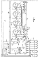
- Figure 2 shows the supply station of the cleaning plant according to the invention for a filling plant with filler and conveyor with four different cleaning systems, which are formed by selective connection and disconnection of the individual components via valves or flaps to or from the respective cleaning circuit on the basis of control signals of the central programme control unit 11, in part operating in parallel.
- the cleaning plant has as central component a fresh water container 12, designed as a static foot, as well as storage containers 13, 14, 15, 16, with the storage container 13 for caustic soda (NaOH), the storage container 14 for hot water, the storage container 15 for acid and the storage container 16 for return water.
- a fresh water container 12 designed as a static foot
- storage containers 13, 14, 15, 16 with the storage container 13 for caustic soda (NaOH), the storage container 14 for hot water, the storage container 15 for acid and the storage container 16 for return water.
- the containers 12-14 have filling connections, return connections and lead connections to draw off the liquids situated in the containers.
- the line 19 for warm water and the line 20 for cold water are connectable, via a three-way valve 12b, alternatively to the fresh water container 12.
- the line 19 is, in this case, connectable via a flap 14d, also to the container 14 for hot water.
- the plant has a dosing station for these cleaning agents in the form of dosing pumps which are generally designated by 27 and which are associated in each instance with an inlet 21-26 and which are connectable, via regulating valves 28, in a manner which will be explained later, selectively into the cleaning circuit.
- dosing pumps which are generally designated by 27 and which are associated in each instance with an inlet 21-26 and which are connectable, via regulating valves 28, in a manner which will be explained later, selectively into the cleaning circuit.
- the cleaning plant according to Figure 2 further has a heating unit with the following assemblies:
- the heating unit is a unit closed in itself and can, depending upon the requirements, be switched into the individual process steps in the differing cleaning systems.
- the heating of the media takes place in the circuit or on a once and for all basis in the course of passage with the predetermination of theoretical temperature via the temperature regulator 32.
- the steam/hot water valve 30 opens and closes while being regulated via the stipulation of the temperature regulator 32.
- the condensate separator 33 is effective in the case of steam heating.
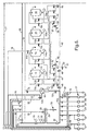
- the parts of the filling plant which are to be cleaned are shown diagrammatically in block form in the right-hand part of Figure 2.
- the block T-CIP symbolizes the conveyor 2 (Figure 1) to be cleaned, with, by way of example, four lines which can be connected and disconnected in each instance via a flap 34 and which lead to the spray heads 5 ( Figure 1) and which are fed from the cleaning lead which still remains to be described.
- the block CIP with the partial blocks tank-CIP, mixer-CIP, tube-CIP and filler-CIP symbolize the filling station 1 according to Figure 1, to which a cleaning lead 3a and a cleaning return 3b are connected.
- the block filler external cleaning symbolizes by way of example four external regions of the filler which are to be cleaned, namely within the subblock 35 the region “sealer; discharge star sealer", within the subblock 36 the region “inlet/discharge star filler”, within the subblock 37 the region “filler silhouette” and within the block 38 the region “rotaflow”. All regions 35-38 together with their associated spray heads 7 are selectively connectable and disconnectable via separate lines with flaps 39, which are fed from the collecting line 6 according to Figure 1.
- a pump 40 is provided, with which there are associated a suction line 41, a second suction line 42 and a third suction line 43.
- the first suction line 41 is connected, via separately activatable flaps 44, in each instance to the lower lead connections of the containers 13-16 and is connected via a flap 45 to a drainage outlet 46 and via a flap 47 to the second suction line 42.
- a drainage outlet 51 via a flap 50, as well as the fresh water container 12 via a flap 12c.
- the third suction line 43 is connected via separately activatable flaps 52 and alternatively actuated flaps 13b,c-16b,c to upper connections of the containers 13-14, the function of which will be further explained later.
- a drainage outlet 54 is further connectable to the third suction line via a flap 53.
- the third suction line is connectable to the second suction line via a flap 55.
- the second suction line is directly connected to the cleaning return 3b, which can be interrupted by means of the flap 56.
- the pump circuit is closed by means of a cleaning lead line 57, which opens into the cleaning lead 3a via flaps 58 and 59, i.e. can be disconnected from the direct cleaning lead 3a.
- the connecting line to the cleaning return 3b is provided upstream of the flap 58 via a flap 60.
- a connecting line to the cleaning return 3b is provided downstream of the flap 58 via a flap 61; in this case, a further flap 56 is connected between the openings of the connecting lines into the cleaning return. With the aid of these flaps, it is possible inter alia to create a short circuit between the cleaning lead 3a or the cleaning lead line 57 and the cleaning return 3b, as will further be explained later.
- the collecting line 4 of the CIP cleaning system for the conveyor 2 (block 34) is connected to the cleaning lead line 57 via a flap 62.
- the recording of the temperature does indeed take place in the cleaning lead and in the cleaning return.
- the temperature measurement point 31 is provided in the lead to monitor an occurring excess temperature, whilst the regulation of the temperature for reasons based on application engineering takes place via the temperature measuring system 65 installed in the cleaning return.
- the supply station according to Figure 2 also has a second cleaning lead line 66, which is connectable via a flap 67 to the collecting line 6 for the filler external cleaning or the hot water flooding.
- This collecting line 6 is also connected via a flap 68 to the cleaning lead line 57 and via a flap 69 to the compressed-air-carrying line 17.
- the second lead line 66 is connectable upstream via regulating valves 70 to the dosing station 37 and is also connected, via a throughflow meter 71 and a valve 72, to the cleaning lead line 57, into which a throughflow meter 73 is also inserted.
- the throughflow quantity meters 71 and 73 serve to monitor the throughflow in the cleaning lead and are preferably designed as magnetically inductive systems.
- the cleaning connection of the fresh water container 12 is further connectable via a flap 74 to the cleaning lead line 57; in this case, the small circle symbolizes a spray head, just as in the case of the containers 13-16.
- the pump 40 passes via the valve 12b from the lines 20 or 19 via the fresh water container 12 and the open flap 12c, when the flap 48 is closed, to the pump 40.
- the pump is preferably frequency-regulated, and conveys as a function of the throughflow quantity predetermined at the throughflow meter 73.
- the valve 72 is closed, so that the cleaning lead line 57 is switched into the circuit.
- the flaps 56, 59, 60 and 61 are closed, whilst the flaps 58 and 62 are open, so that the cleaning lead line 57 is connected to the collecting line 4 leading to the conveyor.
- the flaps 34 in the spray arrangement of the conveyor open one after the other.
- cleaning agents are added by direct injection into the suction line of the pump 40 via the valves 28, and specifically alkaline foam cleansers are added via the inlets 21, acidic foam cleansers via the inlets 22 and disinfecting agents via the inlet 26.
- the dosing of the cleaning agents takes place via the respectively associated dosing pumps 27.
- the respective conveying media of the pump can be heated in the heating unit 29, 30.
- the programme control system 11 ( Figure 1) provides for the following process steps for the cleaning sequence of the CIP cleaning of the conveyor: Process step No.: Designation Step No. 1: Pre-rinsing with water Step No. 2: Apply foam product Step No. 3: Time for action Step No. 4: Rinsing away with water Step No. 5: Apply disinfecting agents Step No. 6: Time for action Step No. 7: Rinsing away with water Step No. 8: Apply belt lubricants
- the foam product can be precisely dosed into the water stream by switching in the valve 28.
- the associated valve 70 is closed, so that no liquid passes into the second cleaning lead line 66.
- the disinfecting agent is dosed in via the inlet and the associated pump 27 and by switching in the associated valve 28, into the water stream in the central suction line 40a.
- the complete disinfecting agent line is vented via the valve 70 prior to a dosing.
- a sufficient intermixing of the substances is accomplished on the one hand by the turbulence in the impeller of the pump 40 and through the stream which is maintained in a turbulent condition in the cleaning lead line 57.
- a further cleaning system is the mentioned "hot water flooding" for the external cleaning of the regions 35-38 of the filler via the collecting line 6 and the flaps 39.
- a hot water flooding is advisable only in circumstances in which a sufficiently large quantity of hot water which is applied in flooding fashion is conducted to the filler within a short period of time.
- temperatures of ⁇ 90°C must be run, in order to achieve a germ-destroying effect.
- hot water stored in the container 14 runs via the associated open flap 44 and the flaps 47, 48 to the pump 40; subsequently, the hot water is additionally heated in the heat exchanger 29 of the heater station, which heat exchanger is heated with hot water/steam via the valve 30 and the line 18.
- a circuit arrangement is created by the control system 11.
- the flap 60 is opened and the flaps 56 and 58 are closed, in order in this way to create a short circuit between the cleaning lead and the cleaning return.
- the hot water - in the circuit - passes via the open flap 55, the third suction line 43 and the associated open flap 52 as well as the open flap 14b at the hot water container 14, back into the container 14. In this way, the complete hot water container 14 is kept to temperature.
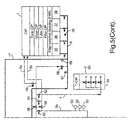
- a third cleaning system is the filler external cleaning in the regions 35-38 via the collecting line 6 and the flaps 39.
- Figure 2 which serve for the supply for this cleaning are described in the text which follows as marked in Figure 5.
- cold/warm water passes via the valve 12b from the lines 20 or 19 via the fresh water container 12 and the open flap 12c, when the flap 48 is closed, to the central suction line 40a of the pump 40.
- the pump 40 is set to a fixed value and the open regulating valve 72 regulates the throughput as a function of the throughflow quantity which is fixedly predetermined at the throughflow measuring system 71.
- the flap 58 is closed, so that the cleaning lead is implemented only via the lead line 66 and not via the lead line 57.
- the flaps 56, 60, 61, 62 are closed in the short circuit arrangement.
- the flap 67 is open, so that the cleaning lead line 66 is connected to the collecting line 6 of the filler external cleaning. Via this collecting line, the respective media are successively utilized at the application regions 35-38 via the flaps 39. In specified process steps, air from the supply line 17 is admitted via the valve 69.
- cleaning agents are likewise added, but by direct injection into the cleaning lead line 66 via the valves 70, and specifically
- the dosing of the cleaning agents takes place in each instance via the associated dosing pump 27.
- the respective media being conveyed can be heated in the heating station.
- the programme control system 11 ( Figure 1) provides for the following steps for the cleaning sequence in the case of the "hot water flooding": Process step No.: Designation Step No. 1: Pre-rinsing with water Step No. 2: Apply foam product + air Step No. 3: Time for action Step No. 4: Rinsing away with water Step No. 5: Apply disinfecting agent Step No. 6: Time for action Step No. 7: Rinsing away with water
- these media are conducted as precisely as possible using the scraper principle ahead of the flaps 39 prior to commencement of the step, i.e., by way of example, the foam product is already being conveyed in the pipeline, but the current application is still in the step "Pre-rinsing with water”.
- the two pumps 27 associated with the foam cleaning tracks 21 and 22 are regulated in their conveying capacity. Via the stipulation of a theoretical concentration and conversion of the total mixing quantity at the throughflow quantity meter 71, the foam product can be dosed precisely into the water stream by switching in the valves 70 associated with the alkaline foam cleanser and the acidic foam cleanser.
- the disinfecting solution is dosed in directly into the water stream flowing to the pump 40 in the central aspiration tube 40a, via the associated pump 27 and through switching in the associated valve 28.
- the complete disinfecting agent line is vented via the valve 75 prior to a dosing.
- a sufficient mixing of the substances is accomplished on the one hand by the turbulence in the impeller of the pump and through the stream which is maintained in a turbulent condition in the cleaning lead tube 66.
- step No. 2 "Apply foam product”
- a quantity of air which is freely adjustable for each area of application is added via the same regulable valve 69 to the foam product premixed in water.
- the fourth cleaning system is the CIP cleaning - marked in Figure 6 - of the filling station, which can be used for the
- This CIP cleaning has the following process steps: Process step No.: Designation Step No. 1: Pre-rinsing with return water from the storage tank Step No. 2: Cleaning under alkaline conditions in the circuit Step No. 3: Intermediate rinsing with fresh water Step No. 4: Return storage in the lye Step No. 5: Cleaning under acidic conditions in the circuit Step No. 6: Return storage of the acid Step No. 7: Intermediate rinsing with fresh water Step No. 8: Cleaning, disinfecting in the circuit Step No. 9: Cleaning, disinfecting with hot water
- cold or warm water passes via the valve 12b from the lines 20 or 19 via the fresh water container 12 and the open flap 12c, when the flap 48 is closed, to the central suction line 40a of the pump 40.
- the stored media lye (in the container 13), acid (in the container 14), hot water (in the container 15) and return water (in the container 16) pass via the flap 44 which is in each case open in the first suction line 41 and via the flaps 47 and 48 to the central suction line 40a of the pump 40.
- the leakage flap 45 Via the leakage flap 45, the residual quantity of product is discharged into the drainage outlet 46 between the individual steps, in order to prevent mixing and reaction between the different stored media.
- the neutral position of the flaps 58 and 60 sets the path via the open flap 49 for the CIP cleaning.
- the path settings within the applications are carried out by the respective external control and are transmitted by means of a clearance signal to the central unit.
- the pump 40 is frequency-regulated and conveys as a function of the throughflow quantity predetermined at the throughflow measuring system 73.
- the respective media being conveyed can be heated via the heating unit.
- the valve 72 is closed.
- the cleaning return can be switched via the flaps
- the supply station is equipped with the second suction line 42 for the reason that on this basis it is possible to circumvent the storage tank in the course of cleaning.
- This volume may be many times the required circuit volume.
- the third suction line 43 is installed; this makes it possible, when a fresh water buffer is produced and with acid from the storage tank 15, to return the lye of the lye circuit to storage in the storage tank 13 for lye via the associated (left-hand) flap 52.
- the stored media lye, acid, return water and hot water can be conducted into the corresponding storage tank 13-16 via the flap 52 which is in each instance open in the third suction line 43 together with the associated flaps 13b, 14b, 15b and 16b in the tank infeed.
- the leakage flap 53 Via the leakage flap 53, the residual quantity of product of the respective stored medium is drained off into the drainage outlet 54 between the individual steps, in order to prevent mixing and reaction between the different stored media.
- the third suction line 43 additionally makes it possible to prime the quantity contained in a lye or acid storage tank 13 or 15, independently of cleaning.
- the flap 60 is opened and the flaps 58 and 56 are closed, in order to create a short circuit between cleaning lead and cleaning return.
- the quantity in the respective storage tank is irrelevant, since via a continuous filling level measurement the precise quantity is known to the programme control system 11 ( Figure 1), which then computes the corresponding quantity of the respective storage medium, which is required for priming to a concentration X.
- the conductivity of the medium, which conductivity is required for this purpose is determined via the temperature compensated conductivity probe 63 in the cleaning return 3b.
- the flaps 13c, 14c, 15c and 16c are to be opened in each instance.
- the cleaning of the fresh water container 12 likewise takes place via a spray head represented symbolically by a circle, but the container is cleaned via the cleaning lead 57.
- the flap 74 is open and the flaps 60 and 58 are closed.
- the complete disinfecting agent line is vented via the valve 75 prior to a dosing.
Landscapes
- Engineering & Computer Science (AREA)
- Mechanical Engineering (AREA)
- Cleaning By Liquid Or Steam (AREA)
- Cleaning In General (AREA)
- Filling Of Jars Or Cans And Processes For Cleaning And Sealing Jars (AREA)
Claims (10)
- Anlage zum Reinigen einer Abfüllanlage mit einer Füllvorrichtung (1) und Förderer (2), welche Anlage ein CIP-Reinigungssystem (3, 4, 5) für die Füllvorrichtung (1) und den Förderer (2) sowie ein Füllvorrichtungsaußenreinigungssystem (6, 7) und ein Heißwasserflutungssystem (8, 9) umfasst, dadurch gekennzeichnet, dass für alle Teilreinigungssysteme vorgesehen sind:in einem gemeinsamen zentralen Reinigungskreislauf (40a, 57) eine gemeinsame Versorgungsstation (10), umfassend die Komponentenwelche mit Hilfe von Ventilen und Drehschieberklappen wahlweise in den Reinigungskreis zugeschaltet und von diesem abgetrennt werden können,Frischwasserbehälter (12)Speicherbehälter (13-16) für Reinigungslösungen oder Spülwasser;eine Erhitzungsstation (29) zum Erhitzen der Reinigungslösungen und zum Erzeugen von Heißwasser;eine Dosierstation (27) zum Dosieren der jeweiligen Reinigungslösung und zum Wiederverwenden von gespeicherten Lösungen,ein Programmsteuerungssystem (11), das Programmteile sowohl für eine aufeinanderfolgende als auch für eine teilweise parallele Aktivierung der Teilreinigungssysteme besitzt, undein gemeinsames Teilleitungssystem, um es teilweise für alle Reinigungskomponenten zu verwenden.
- Anlage nach Anspruch 1, dadurch gekennzeichnet, dass der gemeinsame zentrale Reinigungskreislauf eine zentrale Vorlaufpumpe (40) mit einer zentralen Saugleitung (40a) und eine über die Erhitzungsstation (29) geführte zentrale Reinigungsvorlaufleitung (57) aufweist, dass mit der zentralen Saugleitung (40a) einerseits der Frischwasserbehälter (12), der über eine Ventilanordnung (12b) alternativ mit kaltem oder warmem Wasser gespeist werden kann, mit seiner Vorlauföffnung über eine Drehschieberklappe (12c) und andererseits die Speicherbehälter (13-16) mit vier gespeicherten Medien Lauge, Heißwasser, Säure und Rücklaufwasser mit ihren Vorlauföffnungen jeweils über zugehörige Drehschieberklappen (44), eine gemeinsame erste Saugleitung (41), eine Drehschieberklappe (47) und eine den Anschluss des Frischwasserbehälters (12) von den Speichertanks (13-16) abkoppelnde Drehschieberklappe (48) verbindbar sind, und dass die zentrale Reinigungsvorlaufleitung (57) über eine Drehschieberklappe (59) mit dem Reinigungsvorlauf (3a) der Füllvorrichtungs-CIP-Reinigung sowie über eine Drehschieberklappe (62) mit einer Sammelleitung (4) mit stromabwärts angeordneten Drehschieberklappen (34) des CIP-Reinigungssystems (4, 5) des Förderers (2) und über eine Drehschieberklappe (68) mit einer Sammelleitung (6) mit stromabwärts angeordneten Drehschieberklappen (39) des Heißwasserflutungssystems verbindbar ist.
- Anlage nach Anspruch 2, dadurch gekennzeichnet, dass eine zweite Reinigungsvorlaufleitung (66) vorgesehen ist, die über ein Ventil (72) mit der zentralen Reinigungsvorlaufleitung (57) verbindbar ist und die über eine Drehschieberklappe (67) mit der Sammelleitung (6) mit stromabwärts angeordneten Drehschieberventilklappen (39) des Füllvorrichtungsaußenreinigungssystems verbindbar ist.
- Anlage nach Anspruch 2 oder 3, dadurch gekennzeichnet, dass der Reinigungsrücklauf (3b) der Füllvorrichtungs-CIP-Reinigung über eine Drehschieberklappe (55) mit einer dritten Saugleitung (43) verbindbar ist, mit der die Speichereinlässe der Speicherbehälter (13-16) jeweils über Drehschieberventilklappen (52, 13b-16b) verbindbar sind.
- Anlage nach einem der Ansprüche 3 oder 4, dadurch gekennzeichnet, dass die gemeinsame Dosierstation (27) für Reinigungsmittel und Desinfektionsmittel einerseits über Ventile (28) mit der zentralen Saugleitung (40a) der Pumpe (40) und andererseits über Ventile (70) mit der zweiten Reinigungsvorlaufleitung (66) verbindbar ist.
- Anlage nach einem der Ansprüche 2 bis 5, dadurch gekennzeichnet, dass eine Drehschieberklappenschaltanordnung (56, 58, 60, 61) vorgesehen ist, über die eine Verbindung zwischen der zentralen Reinigungsvorlaufleitung (57) und dem Reinigungsrücklauf (3b) der Füllvorrichtungs-CIP-Reinigung schaltbar ist.
- Anlage nach einem der Ansprüche 4 bis 6, dadurch gekennzeichnet, dass zwischen der Verbindung von der dritten Saugleitung (43) mit der Drehschieberklappe (55) zum Reinigungsrücklauf (3b) und der Verbindung von der ersten Saugleitung (41) mit der Drehschieberklappe (47) zur zentralen Saugleitung (40a) der Pumpe (40) eine zweite Saugleitung (42) eingefügt ist, die einen Bypass für den Rücklauf der gespeicherten Medien in die Speicherbehälter (13-16) bildet.
- Anlage nach den Ansprüchen 6 und 7, dadurch gekennzeichnet, dass in der Betriebsart Heißwasserflutung die zweite Saugleitung (42) über eine Drehschieberklappe (49) abgetrennt ist, und die dritte Saugleitung (43), die mit der zweiten Reinigungsvorlaufleitung (57) verbunden ist, über die Drehschieberklappe (55) sowie die mit dem Heißwasserbehälter (14) verbundene Drehschieberklappe (52, 14b) aktiviert ist, um einen Kreislauf für das Heißwasser zu bilden.
- Anlage nach den Ansprüchen 6 und 7, dadurch gekennzeichnet, dass für eine Selbstreinigung der Speicherbehälter (13-16) die zweite Saugleitung (42) über eine Drehschieberklappe (49) abgetrennt und die dritte Saugleitung (43), die mit der zentralen Reinigungsvorlaufleitung (57) verbunden ist, über die Drehschieberklappe (55) sowie die mit dem jeweiligen Speicherbehälter (13-16) verbundene Drehschieberklappe (52) und die mit der jeweiligen Reinigungsleitung verbundene Drehschieberklappe (13c-16c) aktiviert wird.
- Anlage nach einem der Ansprüche 2 bis 9, dadurch gekennzeichnet, dass eine Auslaufdrehschieberklappe (45) mit einem stromabwärts angeordneten Entleerungsauslass (46) für die erste Saugleitung (41) vorgesehen ist, und in derselben Weise eins Drehschieberklappe (53) mit einem stromabwärts angeordneten Entleerungsauslass (54) für die dritte Saugleitung (43) vorgesehen ist, und eine Drehschieberklappe (50) mit einem stromabwärts angeordneten Entleerungsauslass (51) für die zweite Saugleitung (42) vorgesehen ist.
Applications Claiming Priority (2)
| Application Number | Priority Date | Filing Date | Title |
|---|---|---|---|
| DE19741242 | 1997-09-18 | ||
| DE19741242A DE19741242C1 (de) | 1997-09-18 | 1997-09-18 | Anlage zum Reinigen einer Abfüllanlage |
Publications (2)
| Publication Number | Publication Date |
|---|---|
| EP0903320A1 EP0903320A1 (de) | 1999-03-24 |
| EP0903320B1 true EP0903320B1 (de) | 2002-11-27 |
Family
ID=7842858
Family Applications (1)
| Application Number | Title | Priority Date | Filing Date |
|---|---|---|---|
| EP98202703A Expired - Lifetime EP0903320B1 (de) | 1997-09-18 | 1998-08-12 | CIP-System zur Reinigung einer Abfüllanlage |
Country Status (6)
| Country | Link |
|---|---|
| US (1) | US6014994A (de) |
| EP (1) | EP0903320B1 (de) |
| CA (1) | CA2246529C (de) |
| DE (2) | DE19741242C1 (de) |
| DK (1) | DK0903320T3 (de) |
| ES (1) | ES2187878T3 (de) |
Cited By (2)
| Publication number | Priority date | Publication date | Assignee | Title |
|---|---|---|---|---|
| EP3620426B1 (de) | 2012-11-16 | 2023-03-01 | Dai Nippon Printing Co., Ltd. | Vorrichtung zum abfüllen eines getränks mit mitteln zum reinigen und sterilisieren der vorrichtung |
| EP4119452A4 (de) * | 2020-03-12 | 2024-04-10 | Dai Nippon Printing Co., Ltd. | Sterilisationsverfahren |
Families Citing this family (41)
| Publication number | Priority date | Publication date | Assignee | Title |
|---|---|---|---|---|
| US6391122B1 (en) * | 1999-11-23 | 2002-05-21 | Diversey Lever, Inc. | Segmented process for cleaning-in-place |
| DE10103091A1 (de) * | 2001-01-24 | 2002-08-01 | Ecolab Gmbh & Co Ohg | Verfahren zur Herstellung, Förderung und Dosierung einer Lösung und Vorrichtung zur Durchführung des Verfahrens |
| DE20108017U1 (de) * | 2001-05-11 | 2002-04-18 | Zentes Unitex GmbH, 63456 Hanau | Reinigungsanlage zur Reinigung von Produktionsanlagen der Nahrungsmittel-, Getränke-, Pharma- und Kosmetikindustrie |
| ITBO20020633A1 (it) | 2002-10-08 | 2004-04-09 | Azionaria Costruzioni Acma Spa | Metodo e macchina per l'erogazione di sostanze fluide all'interno di contenitori |
| US6767408B2 (en) * | 2002-12-18 | 2004-07-27 | Hydrite Chemical Co. | Monitoring device and method for operating clean-in-place system |
| US7143793B2 (en) * | 2005-02-18 | 2006-12-05 | Johnsondiversey, Inc. | Cleaning system for a filling machine |
| US20060286676A1 (en) * | 2005-06-17 | 2006-12-21 | Van Camp James R | Fluorometric method for monitoring a clean-in-place system |
| WO2007128282A1 (de) * | 2006-05-05 | 2007-11-15 | Multivac Sepp Haggenmüller Gmbh & Co. Kg | Verpackungsmaschine |
| EP2131665A1 (de) * | 2007-03-15 | 2009-12-16 | The Coca-Cola Company | Verfahren zur hemmung von benzolbildung in getränken und auf diese weise hergestellte getränke |
| DE102007022798A1 (de) † | 2007-05-11 | 2008-11-13 | Sig Technology Ag | Verfahren und Vorrichtung zum gleichzeitigen Reinigen mehrerer Rohrleitungen oder Rohrleitungssysteme |
| US20100037984A1 (en) * | 2008-08-12 | 2010-02-18 | The Coca-Cola Company | Aseptic filling device for carbonated beverages |
| DE102009020912A1 (de) * | 2009-05-12 | 2010-11-18 | Krones Ag | Verrohrungssystem |
| DE102010038319A1 (de) | 2010-07-23 | 2012-01-26 | Krones Aktiengesellschaft | Verfahren und Vorrichtung zur Medienführung durch eine Behandlungsanlage für ein flüssiges Produkt |
| DE102011050955A1 (de) * | 2011-06-09 | 2012-12-13 | Elopak Systems Ag | Kondensatableiter und Verfahren zum Ableiten von Kondensat |
| DE102011108092A1 (de) * | 2011-07-19 | 2013-01-24 | Multivac Sepp Haggenmüller Gmbh & Co. Kg | Reinigungsverfahren und -system für Vakuumpumpe |
| JP5838720B2 (ja) | 2011-10-25 | 2016-01-06 | 大日本印刷株式会社 | 殺菌処理ライン及びその浄化方法 |
| JP2013141613A (ja) * | 2012-01-06 | 2013-07-22 | Toshiba Carrier Corp | 産業用加熱装置 |
| CN102615070B (zh) * | 2012-04-17 | 2014-12-24 | 广州轻机机械设备有限公司 | 一种全自动外部泡沫清洗系统 |
| DE102013005674B3 (de) | 2013-04-03 | 2014-06-12 | Gea Tds Gmbh | Reinigungsverfahren und Reinigungsanlage für eine heiß zu reinigende Prozessanlage |
| CN104100837B (zh) * | 2013-04-05 | 2018-01-23 | 克朗斯公司 | 为消耗器供应清洁液和/或消毒液的装置 |
| US20140299223A1 (en) * | 2013-04-05 | 2014-10-09 | Krones Ag | Device for supplying consumers with cleaning and/or disinfection fluid |
| EP2786811B1 (de) * | 2013-04-05 | 2016-06-22 | Krones AG | Vorrichtung zur Versorgung von Verbrauchern mit Reinigungs- und/oder Desinfektionsfluid |
| DE102014102529B4 (de) * | 2014-02-26 | 2017-12-07 | Netzsch-Feinmahltechnik Gmbh | Anlage zur herstellung und / oder aufbereitung von confectionery-massen und verfahren zur reinigung einer anlage zur herstellung und / oder aufbereitung von confectionery-massen |
| DE102014008968A1 (de) * | 2014-06-23 | 2015-12-24 | Robert Sporer | Waschanlage zum Reinigen von Teilen wie Maschinenteilen oder dergleichen |
| CN104096692B (zh) * | 2014-06-30 | 2017-08-25 | 吐鲁番楼兰酒庄股份有限公司 | 自动清洗装置及其清洗方法 |
| DE102015100893A1 (de) * | 2015-01-22 | 2016-07-28 | Krones Aktiengesellschaft | Vorrichtung zum Reinigen und Sterilisieren eines Füllventils einer Getränkeabfüllanlage zum Befüllen eines Behälters mit einem Füllprodukt |
| DE102015106017B4 (de) * | 2015-04-20 | 2019-02-21 | Schulz Gmbh | Vorrichtung zur Entnahme von Desinfektions- oder Reinigungsmittel-Gebrauchslösungen |
| DE102015209354A1 (de) * | 2015-05-21 | 2016-05-19 | Jürgen Löhrke GmbH | Cleaning-in-place-Verfahren |
| JP6664916B2 (ja) * | 2015-09-28 | 2020-03-13 | サントリーホールディングス株式会社 | 殺菌方法及び殺菌装置 |
| DE102015119318A1 (de) * | 2015-11-10 | 2017-05-11 | Krones Ag | Vorrichtung zum Reinigen eines zu reinigenden Anlagenteils einer Getränkeabfüllanlage |
| US10345058B1 (en) | 2015-11-18 | 2019-07-09 | Gradiant Corporation | Scale removal in humidification-dehumidification systems |
| CN107185894A (zh) * | 2016-03-14 | 2017-09-22 | 内蒙古伊利实业集团股份有限公司 | 一种应用氧化电位水对乳制品生产设备进行原位清洗的系统装置和方法 |
| US10513445B2 (en) | 2016-05-20 | 2019-12-24 | Gradiant Corporation | Control system and method for multiple parallel desalination systems |
| DE102016109504A1 (de) * | 2016-05-24 | 2017-11-30 | Lutz Pumpen Gmbh | Vorrichtung zur Reinigung von Förderaggregaten für fliessfähige Medien |
| DE102017106337A1 (de) * | 2017-03-23 | 2018-09-27 | Krones Ag | Vorrichtung zum Befüllen eines Behälters mit einem Füllprodukt |
| WO2019037842A1 (de) * | 2017-08-23 | 2019-02-28 | Siemens Aktiengesellschaft | System und verfahren zum erstellen und durchführen eines anlagenreinigungsprozesses für verfahrenstechnische anlagen |
| MY204807A (en) * | 2018-03-29 | 2024-09-14 | Dainippon Printing Co Ltd | Deodorizing method |
| DK180097B1 (en) | 2018-04-19 | 2020-04-30 | Purgatio A/S | A method for measuring an entity of interest in a stream of rinsing water |
| DE102019110665A1 (de) * | 2019-04-25 | 2020-10-29 | Khs Gmbh | Verfahren zur CIP-Reinigung eines Füllelements einer Füllmaschine und Füllmaschine |
| DE102019117084A1 (de) * | 2019-06-25 | 2020-12-31 | Dürr Systems Ag | Reinigungsanlage und Reinigungsverfahren insbesondere für Behandlungsanlagen in der Lackiertechnik |
| KR102339679B1 (ko) * | 2020-11-17 | 2021-12-16 | 씨제이제일제당 (주) | 제자리세정이 가능한 식품 처리 시스템 및 그 세척방법 |
Family Cites Families (11)
| Publication number | Priority date | Publication date | Assignee | Title |
|---|---|---|---|---|
| US3945411A (en) * | 1974-04-01 | 1976-03-23 | Mojonnier Bros. Co. | System for mixing various kinds of fluids for producing beverages, and means for cleaning the apparatus between operations |
| US4501622A (en) * | 1983-11-08 | 1985-02-26 | Marchadour Jean Charles | Apparatus and method for cleaning flowable material filling devices |
| EP0162968B1 (de) * | 1984-05-26 | 1987-12-02 | Shikoku Kakoki Co., Ltd. | Verpackungsmaschine |
| DE3924188A1 (de) * | 1989-07-21 | 1991-01-31 | Orthmann & Herbst | Aussensterilisierungsvorrichtung fuer rotierende getraenkefueller |
| US5329950A (en) * | 1993-05-14 | 1994-07-19 | Sanirab Corporation | Clean-in-place process and equipment |
| DE4326601A1 (de) * | 1993-08-07 | 1995-02-09 | Kronseder Maschf Krones | Verfahren und Vorrichtung zum sterilen Abfüllen von Getränken in Flaschen |
| DE9404610U1 (de) * | 1994-03-18 | 1994-05-19 | Khs Maschinen- Und Anlagenbau Ag, 47057 Duisburg | Vorrichtung zur Außenreinigung von Behälterbehandlungsmaschinen |
| DE4434407A1 (de) * | 1994-09-26 | 1996-03-28 | Diversey Corp | Anlage zum Reinigen und Befüllen einer Folge von Getränkebehältern |
| DE19508357A1 (de) * | 1995-03-10 | 1996-09-12 | Diversey Corp | Reinigungsvorrichtung |
| US5941290A (en) * | 1998-02-19 | 1999-08-24 | Diversey Lever, Inc. | Cleaning system for industrial uses |
| DE19808357A1 (de) * | 1998-02-27 | 1998-08-27 | Markus Hagemann | Gehrungslehre zum Schneiden von Rohrisolierung |
-
1997
- 1997-09-18 DE DE19741242A patent/DE19741242C1/de not_active Expired - Fee Related
-
1998
- 1998-08-12 EP EP98202703A patent/EP0903320B1/de not_active Expired - Lifetime
- 1998-08-12 DE DE69809668T patent/DE69809668T2/de not_active Expired - Fee Related
- 1998-08-12 ES ES98202703T patent/ES2187878T3/es not_active Expired - Lifetime
- 1998-08-12 DK DK98202703T patent/DK0903320T3/da active
- 1998-09-03 CA CA002246529A patent/CA2246529C/en not_active Expired - Lifetime
- 1998-09-14 US US09/152,781 patent/US6014994A/en not_active Expired - Lifetime
Cited By (2)
| Publication number | Priority date | Publication date | Assignee | Title |
|---|---|---|---|---|
| EP3620426B1 (de) | 2012-11-16 | 2023-03-01 | Dai Nippon Printing Co., Ltd. | Vorrichtung zum abfüllen eines getränks mit mitteln zum reinigen und sterilisieren der vorrichtung |
| EP4119452A4 (de) * | 2020-03-12 | 2024-04-10 | Dai Nippon Printing Co., Ltd. | Sterilisationsverfahren |
Also Published As
| Publication number | Publication date |
|---|---|
| EP0903320A1 (de) | 1999-03-24 |
| CA2246529C (en) | 2007-04-17 |
| ES2187878T3 (es) | 2003-06-16 |
| DE69809668D1 (de) | 2003-01-09 |
| DK0903320T3 (da) | 2003-03-24 |
| CA2246529A1 (en) | 1999-03-18 |
| DE19741242C1 (de) | 1999-07-08 |
| US6014994A (en) | 2000-01-18 |
| DE69809668T2 (de) | 2003-07-24 |
Similar Documents
| Publication | Publication Date | Title |
|---|---|---|
| EP0903320B1 (de) | CIP-System zur Reinigung einer Abfüllanlage | |
| RU2468986C2 (ru) | Система для безразборной очистки разливочных устройств для розлива напитка | |
| US5348058A (en) | Clean-in-place filling machine | |
| EP2772319B1 (de) | Sterilisationsverarbeitungslinie und verfahren zur reinigung dafür | |
| AU2005232788B2 (en) | Cleaning method and apparatus | |
| US3945411A (en) | System for mixing various kinds of fluids for producing beverages, and means for cleaning the apparatus between operations | |
| JP2022141790A (ja) | 撹拌処理内蔵式食品加工装置 | |
| MXPA06001547A (es) | Montaje higienico de mezclado y espumado de bebidas. | |
| CN102458699B (zh) | 管道系统及管道系统用的操作方法 | |
| CN112897440A (zh) | 具有cip清洁装置的用于填充容器的设备 | |
| CN106917961A (zh) | 用于uht系统的多功能进料阀组及uht系统的生产方法 | |
| CN101700077B (zh) | 一种再制奶酪可移动加工装置 | |
| AU717586B2 (en) | Fill system for primary and secondary products | |
| CN113142457A (zh) | 一种无菌型果粒碳酸饮料混比装置 | |
| CN108651687B (zh) | 一种自助式冰激凌机 | |
| Seiberling et al. | Engineering considerations for CIP/SIP systems | |
| CN208466785U (zh) | 一种冷运箱清洗装置 | |
| CN201518694U (zh) | 一种再制奶酪可移动加工装置 | |
| CN114568940B (zh) | 一种饮品机碳酸与非碳酸饮料同机柔性转换工艺 | |
| CN217997194U (zh) | 发酵装置 | |
| CN222343724U (zh) | 一种用于罐桶内部清洗的清洗系统 | |
| CN219335277U (zh) | 一种一体式电加热cip在线清洗机 | |
| CN224199119U (zh) | 灌装系统 | |
| CN220012120U (zh) | 恒温灌装系统 | |
| CN218979805U (zh) | 一种滴丸设备 |
Legal Events
| Date | Code | Title | Description |
|---|---|---|---|
| PUAI | Public reference made under article 153(3) epc to a published international application that has entered the european phase |
Free format text: ORIGINAL CODE: 0009012 |
|
| AK | Designated contracting states |
Kind code of ref document: A1 Designated state(s): CH DE DK ES FR GB IT LI NL SE |
|
| AX | Request for extension of the european patent |
Free format text: AL;LT;LV;MK;RO;SI |
|
| 17P | Request for examination filed |
Effective date: 19990218 |
|
| RAP1 | Party data changed (applicant data changed or rights of an application transferred) |
Owner name: UNILEVER PLC Owner name: UNILEVER N.V. |
|
| AKX | Designation fees paid |
Free format text: AT BE CH DE DK ES FI FR GB LI |
|
| RBV | Designated contracting states (corrected) |
Designated state(s): CH DE DK ES FR GB IT LI NL SE |
|
| 17Q | First examination report despatched |
Effective date: 20010912 |
|
| GRAG | Despatch of communication of intention to grant |
Free format text: ORIGINAL CODE: EPIDOS AGRA |
|
| GRAG | Despatch of communication of intention to grant |
Free format text: ORIGINAL CODE: EPIDOS AGRA |
|
| GRAH | Despatch of communication of intention to grant a patent |
Free format text: ORIGINAL CODE: EPIDOS IGRA |
|
| GRAH | Despatch of communication of intention to grant a patent |
Free format text: ORIGINAL CODE: EPIDOS IGRA |
|
| GRAA | (expected) grant |
Free format text: ORIGINAL CODE: 0009210 |
|
| RAP1 | Party data changed (applicant data changed or rights of an application transferred) |
Owner name: JOHNSONDIVERSEY, INC. |
|
| AK | Designated contracting states |
Kind code of ref document: B1 Designated state(s): CH DE DK ES FR GB IT LI NL SE |
|
| REG | Reference to a national code |
Ref country code: GB Ref legal event code: FG4D |
|
| REG | Reference to a national code |
Ref country code: CH Ref legal event code: EP |
|
| REF | Corresponds to: |
Ref document number: 69809668 Country of ref document: DE Date of ref document: 20030109 |
|
| REG | Reference to a national code |
Ref country code: CH Ref legal event code: NV Representative=s name: E. BLUM & CO. PATENTANWAELTE |
|
| REG | Reference to a national code |
Ref country code: DK Ref legal event code: T3 |
|
| ET | Fr: translation filed | ||
| REG | Reference to a national code |
Ref country code: ES Ref legal event code: FG2A Ref document number: 2187878 Country of ref document: ES Kind code of ref document: T3 |
|
| PLBE | No opposition filed within time limit |
Free format text: ORIGINAL CODE: 0009261 |
|
| STAA | Information on the status of an ep patent application or granted ep patent |
Free format text: STATUS: NO OPPOSITION FILED WITHIN TIME LIMIT |
|
| 26N | No opposition filed |
Effective date: 20030828 |
|
| PGFP | Annual fee paid to national office [announced via postgrant information from national office to epo] |
Ref country code: DE Payment date: 20050930 Year of fee payment: 8 |
|
| PG25 | Lapsed in a contracting state [announced via postgrant information from national office to epo] |
Ref country code: DE Free format text: LAPSE BECAUSE OF NON-PAYMENT OF DUE FEES Effective date: 20070301 |
|
| REG | Reference to a national code |
Ref country code: CH Ref legal event code: PFA Owner name: JOHNSONDIVERSEY, INC. Free format text: JOHNSONDIVERSEY, INC.#8310 16TH STREET#STURTEVANT, WISCONSIN 53177-0902 (US) -TRANSFER TO- JOHNSONDIVERSEY, INC.#8310 16TH STREET#STURTEVANT, WISCONSIN 53177-0902 (US) |
|
| REG | Reference to a national code |
Ref country code: CH Ref legal event code: PFA Owner name: DIVERSEY, INC. Free format text: JOHNSONDIVERSEY, INC.#8310 16TH STREET#STURTEVANT, WISCONSIN 53177-0902 (US) -TRANSFER TO- DIVERSEY, INC.#8310 16TH STREET - M/S 509#STURTEVANT, WI 53177-0902 (US) |
|
| REG | Reference to a national code |
Ref country code: NL Ref legal event code: TD Effective date: 20101013 |
|
| REG | Reference to a national code |
Ref country code: FR Ref legal event code: CD |
|
| REG | Reference to a national code |
Ref country code: ES Ref legal event code: PC2A Owner name: DIVERSEY, INC. Effective date: 20110429 |
|
| REG | Reference to a national code |
Ref country code: NL Ref legal event code: PLEX Effective date: 20120724 |
|
| REG | Reference to a national code |
Ref country code: FR Ref legal event code: PLFP Year of fee payment: 19 |
|
| REG | Reference to a national code |
Ref country code: FR Ref legal event code: PLFP Year of fee payment: 20 |
|
| PGFP | Annual fee paid to national office [announced via postgrant information from national office to epo] |
Ref country code: NL Payment date: 20170826 Year of fee payment: 20 |
|
| PGFP | Annual fee paid to national office [announced via postgrant information from national office to epo] |
Ref country code: GB Payment date: 20170829 Year of fee payment: 20 Ref country code: IT Payment date: 20170823 Year of fee payment: 20 Ref country code: CH Payment date: 20170827 Year of fee payment: 20 Ref country code: ES Payment date: 20170901 Year of fee payment: 20 Ref country code: FR Payment date: 20170825 Year of fee payment: 20 |
|
| PGFP | Annual fee paid to national office [announced via postgrant information from national office to epo] |
Ref country code: SE Payment date: 20170829 Year of fee payment: 20 Ref country code: DK Payment date: 20170825 Year of fee payment: 20 |
|
| REG | Reference to a national code |
Ref country code: DK Ref legal event code: EUP Effective date: 20180812 |
|
| REG | Reference to a national code |
Ref country code: CH Ref legal event code: PL Ref country code: NL Ref legal event code: MK Effective date: 20180811 |
|
| REG | Reference to a national code |
Ref country code: GB Ref legal event code: PE20 Expiry date: 20180811 |
|
| REG | Reference to a national code |
Ref country code: SE Ref legal event code: EUG |
|
| PG25 | Lapsed in a contracting state [announced via postgrant information from national office to epo] |
Ref country code: GB Free format text: LAPSE BECAUSE OF EXPIRATION OF PROTECTION Effective date: 20180811 |
|
| REG | Reference to a national code |
Ref country code: ES Ref legal event code: FD2A Effective date: 20201110 |
|
| PG25 | Lapsed in a contracting state [announced via postgrant information from national office to epo] |
Ref country code: ES Free format text: LAPSE BECAUSE OF EXPIRATION OF PROTECTION Effective date: 20180813 |