EP0903312B1 - Distributeur de ruban adhésif et son utilisation - Google Patents
Distributeur de ruban adhésif et son utilisation Download PDFInfo
- Publication number
- EP0903312B1 EP0903312B1 EP98117041A EP98117041A EP0903312B1 EP 0903312 B1 EP0903312 B1 EP 0903312B1 EP 98117041 A EP98117041 A EP 98117041A EP 98117041 A EP98117041 A EP 98117041A EP 0903312 B1 EP0903312 B1 EP 0903312B1
- Authority
- EP
- European Patent Office
- Prior art keywords
- cutting
- adhesive tape
- knife
- adhesive
- blades
- Prior art date
- Legal status (The legal status is an assumption and is not a legal conclusion. Google has not performed a legal analysis and makes no representation as to the accuracy of the status listed.)
- Expired - Lifetime
Links
- 239000002390 adhesive tape Substances 0.000 title claims description 48
- 238000005520 cutting process Methods 0.000 claims description 103
- 230000006378 damage Effects 0.000 claims description 23
- 208000027418 Wounds and injury Diseases 0.000 claims description 20
- 208000014674 injury Diseases 0.000 claims description 20
- 230000000284 resting effect Effects 0.000 claims description 7
- 229920000098 polyolefin Polymers 0.000 claims description 2
- 239000002313 adhesive film Substances 0.000 description 66
- 238000012360 testing method Methods 0.000 description 7
- 239000000853 adhesive Substances 0.000 description 5
- 230000001070 adhesive effect Effects 0.000 description 5
- 239000000463 material Substances 0.000 description 5
- 229910000831 Steel Inorganic materials 0.000 description 4
- 239000010959 steel Substances 0.000 description 4
- -1 Polypropylen Polymers 0.000 description 3
- 239000004743 Polypropylene Substances 0.000 description 3
- 239000000969 carrier Substances 0.000 description 3
- 238000012545 processing Methods 0.000 description 3
- 230000001681 protective effect Effects 0.000 description 3
- 229920006378 biaxially oriented polypropylene Polymers 0.000 description 2
- 239000011127 biaxially oriented polypropylene Substances 0.000 description 2
- 230000015572 biosynthetic process Effects 0.000 description 2
- 238000002474 experimental method Methods 0.000 description 2
- 239000002655 kraft paper Substances 0.000 description 2
- 229910052751 metal Inorganic materials 0.000 description 2
- 239000002184 metal Substances 0.000 description 2
- 239000004033 plastic Substances 0.000 description 2
- 229920003023 plastic Polymers 0.000 description 2
- 229920000139 polyethylene terephthalate Polymers 0.000 description 2
- 239000005020 polyethylene terephthalate Substances 0.000 description 2
- 229920001155 polypropylene Polymers 0.000 description 2
- 230000001012 protector Effects 0.000 description 2
- 238000012546 transfer Methods 0.000 description 2
- 206010003830 Automatism Diseases 0.000 description 1
- 229920000298 Cellophane Polymers 0.000 description 1
- 241000985128 Cladium mariscus Species 0.000 description 1
- 208000012880 Finger injury Diseases 0.000 description 1
- 241001295925 Gegenes Species 0.000 description 1
- 239000004698 Polyethylene Substances 0.000 description 1
- NRTOMJZYCJJWKI-UHFFFAOYSA-N Titanium nitride Chemical compound [Ti]#N NRTOMJZYCJJWKI-UHFFFAOYSA-N 0.000 description 1
- 230000006978 adaptation Effects 0.000 description 1
- 238000004026 adhesive bonding Methods 0.000 description 1
- 229910052782 aluminium Inorganic materials 0.000 description 1
- XAGFODPZIPBFFR-UHFFFAOYSA-N aluminium Chemical compound [Al] XAGFODPZIPBFFR-UHFFFAOYSA-N 0.000 description 1
- 230000009286 beneficial effect Effects 0.000 description 1
- YFXPPSKYMBTNAV-UHFFFAOYSA-N bensultap Chemical compound C=1C=CC=CC=1S(=O)(=O)SCC(N(C)C)CSS(=O)(=O)C1=CC=CC=C1 YFXPPSKYMBTNAV-UHFFFAOYSA-N 0.000 description 1
- 239000012876 carrier material Substances 0.000 description 1
- 229920002301 cellulose acetate Polymers 0.000 description 1
- 239000011248 coating agent Substances 0.000 description 1
- 238000000576 coating method Methods 0.000 description 1
- 229920001577 copolymer Polymers 0.000 description 1
- 210000004905 finger nail Anatomy 0.000 description 1
- 229920001519 homopolymer Polymers 0.000 description 1
- 238000002347 injection Methods 0.000 description 1
- 239000007924 injection Substances 0.000 description 1
- 238000001746 injection moulding Methods 0.000 description 1
- 230000010354 integration Effects 0.000 description 1
- 238000004519 manufacturing process Methods 0.000 description 1
- 238000000034 method Methods 0.000 description 1
- 239000000203 mixture Substances 0.000 description 1
- WXZMFSXDPGVJKK-UHFFFAOYSA-N pentaerythritol Chemical compound OCC(CO)(CO)CO WXZMFSXDPGVJKK-UHFFFAOYSA-N 0.000 description 1
- 239000007858 starting material Substances 0.000 description 1
- 238000003860 storage Methods 0.000 description 1
- 239000000758 substrate Substances 0.000 description 1
- 238000010998 test method Methods 0.000 description 1
- 125000000391 vinyl group Chemical group [H]C([*])=C([H])[H] 0.000 description 1
- 229920002554 vinyl polymer Polymers 0.000 description 1
Images
Classifications
-
- B—PERFORMING OPERATIONS; TRANSPORTING
- B65—CONVEYING; PACKING; STORING; HANDLING THIN OR FILAMENTARY MATERIAL
- B65H—HANDLING THIN OR FILAMENTARY MATERIAL, e.g. SHEETS, WEBS, CABLES
- B65H35/00—Delivering articles from cutting or line-perforating machines; Article or web delivery apparatus incorporating cutting or line-perforating devices, e.g. adhesive tape dispensers
- B65H35/0006—Article or web delivery apparatus incorporating cutting or line-perforating devices
- B65H35/002—Hand-held or table apparatus
- B65H35/0026—Hand-held or table apparatus for delivering pressure-sensitive adhesive tape
-
- B—PERFORMING OPERATIONS; TRANSPORTING
- B65—CONVEYING; PACKING; STORING; HANDLING THIN OR FILAMENTARY MATERIAL
- B65H—HANDLING THIN OR FILAMENTARY MATERIAL, e.g. SHEETS, WEBS, CABLES
- B65H35/00—Delivering articles from cutting or line-perforating machines; Article or web delivery apparatus incorporating cutting or line-perforating devices, e.g. adhesive tape dispensers
- B65H35/0006—Article or web delivery apparatus incorporating cutting or line-perforating devices
- B65H35/0073—Details
- B65H35/008—Arrangements or adaptations of cutting devices
-
- Y—GENERAL TAGGING OF NEW TECHNOLOGICAL DEVELOPMENTS; GENERAL TAGGING OF CROSS-SECTIONAL TECHNOLOGIES SPANNING OVER SEVERAL SECTIONS OF THE IPC; TECHNICAL SUBJECTS COVERED BY FORMER USPC CROSS-REFERENCE ART COLLECTIONS [XRACs] AND DIGESTS
- Y10—TECHNICAL SUBJECTS COVERED BY FORMER USPC
- Y10T—TECHNICAL SUBJECTS COVERED BY FORMER US CLASSIFICATION
- Y10T156/00—Adhesive bonding and miscellaneous chemical manufacture
- Y10T156/17—Surface bonding means and/or assemblymeans with work feeding or handling means
- Y10T156/1788—Work traversing type and/or means applying work to wall or static structure
- Y10T156/1795—Implement carried web supply
-
- Y—GENERAL TAGGING OF NEW TECHNOLOGICAL DEVELOPMENTS; GENERAL TAGGING OF CROSS-SECTIONAL TECHNOLOGIES SPANNING OVER SEVERAL SECTIONS OF THE IPC; TECHNICAL SUBJECTS COVERED BY FORMER USPC CROSS-REFERENCE ART COLLECTIONS [XRACs] AND DIGESTS
- Y10—TECHNICAL SUBJECTS COVERED BY FORMER USPC
- Y10T—TECHNICAL SUBJECTS COVERED BY FORMER US CLASSIFICATION
- Y10T225/00—Severing by tearing or breaking
- Y10T225/20—Severing by manually forcing against fixed edge
- Y10T225/205—With feed-out of predetermined length from work supply
- Y10T225/206—Including means to select or adjust feed-out length
-
- Y—GENERAL TAGGING OF NEW TECHNOLOGICAL DEVELOPMENTS; GENERAL TAGGING OF CROSS-SECTIONAL TECHNOLOGIES SPANNING OVER SEVERAL SECTIONS OF THE IPC; TECHNICAL SUBJECTS COVERED BY FORMER USPC CROSS-REFERENCE ART COLLECTIONS [XRACs] AND DIGESTS
- Y10—TECHNICAL SUBJECTS COVERED BY FORMER USPC
- Y10T—TECHNICAL SUBJECTS COVERED BY FORMER US CLASSIFICATION
- Y10T225/00—Severing by tearing or breaking
- Y10T225/20—Severing by manually forcing against fixed edge
- Y10T225/205—With feed-out of predetermined length from work supply
- Y10T225/207—Including feed-out stop for manually pulled work
- Y10T225/209—With feed-out of lead-end to aid initial grasping
-
- Y—GENERAL TAGGING OF NEW TECHNOLOGICAL DEVELOPMENTS; GENERAL TAGGING OF CROSS-SECTIONAL TECHNOLOGIES SPANNING OVER SEVERAL SECTIONS OF THE IPC; TECHNICAL SUBJECTS COVERED BY FORMER USPC CROSS-REFERENCE ART COLLECTIONS [XRACs] AND DIGESTS
- Y10—TECHNICAL SUBJECTS COVERED BY FORMER USPC
- Y10T—TECHNICAL SUBJECTS COVERED BY FORMER US CLASSIFICATION
- Y10T225/00—Severing by tearing or breaking
- Y10T225/20—Severing by manually forcing against fixed edge
- Y10T225/205—With feed-out of predetermined length from work supply
- Y10T225/21—Merely to provide lead-end for manual grasping
-
- Y—GENERAL TAGGING OF NEW TECHNOLOGICAL DEVELOPMENTS; GENERAL TAGGING OF CROSS-SECTIONAL TECHNOLOGIES SPANNING OVER SEVERAL SECTIONS OF THE IPC; TECHNICAL SUBJECTS COVERED BY FORMER USPC CROSS-REFERENCE ART COLLECTIONS [XRACs] AND DIGESTS
- Y10—TECHNICAL SUBJECTS COVERED BY FORMER USPC
- Y10T—TECHNICAL SUBJECTS COVERED BY FORMER US CLASSIFICATION
- Y10T225/00—Severing by tearing or breaking
- Y10T225/20—Severing by manually forcing against fixed edge
- Y10T225/205—With feed-out of predetermined length from work supply
- Y10T225/211—Manually operated feed-out mechanism
-
- Y—GENERAL TAGGING OF NEW TECHNOLOGICAL DEVELOPMENTS; GENERAL TAGGING OF CROSS-SECTIONAL TECHNOLOGIES SPANNING OVER SEVERAL SECTIONS OF THE IPC; TECHNICAL SUBJECTS COVERED BY FORMER USPC CROSS-REFERENCE ART COLLECTIONS [XRACs] AND DIGESTS
- Y10—TECHNICAL SUBJECTS COVERED BY FORMER USPC
- Y10T—TECHNICAL SUBJECTS COVERED BY FORMER US CLASSIFICATION
- Y10T83/00—Cutting
- Y10T83/647—With means to convey work relative to tool station
- Y10T83/664—Roller
- Y10T83/6644—With work-supplying reel
-
- Y—GENERAL TAGGING OF NEW TECHNOLOGICAL DEVELOPMENTS; GENERAL TAGGING OF CROSS-SECTIONAL TECHNOLOGIES SPANNING OVER SEVERAL SECTIONS OF THE IPC; TECHNICAL SUBJECTS COVERED BY FORMER USPC CROSS-REFERENCE ART COLLECTIONS [XRACs] AND DIGESTS
- Y10—TECHNICAL SUBJECTS COVERED BY FORMER USPC
- Y10T—TECHNICAL SUBJECTS COVERED BY FORMER US CLASSIFICATION
- Y10T83/00—Cutting
- Y10T83/727—With means to guide moving work
- Y10T83/739—Positively confines or otherwise determines path of work
-
- Y—GENERAL TAGGING OF NEW TECHNOLOGICAL DEVELOPMENTS; GENERAL TAGGING OF CROSS-SECTIONAL TECHNOLOGIES SPANNING OVER SEVERAL SECTIONS OF THE IPC; TECHNICAL SUBJECTS COVERED BY FORMER USPC CROSS-REFERENCE ART COLLECTIONS [XRACs] AND DIGESTS
- Y10—TECHNICAL SUBJECTS COVERED BY FORMER USPC
- Y10T—TECHNICAL SUBJECTS COVERED BY FORMER US CLASSIFICATION
- Y10T83/00—Cutting
- Y10T83/869—Means to drive or to guide tool
- Y10T83/8798—With simple oscillating motion only
- Y10T83/8817—Axially entending cutting edge
- Y10T83/8818—Axially progressing cut
-
- Y—GENERAL TAGGING OF NEW TECHNOLOGICAL DEVELOPMENTS; GENERAL TAGGING OF CROSS-SECTIONAL TECHNOLOGIES SPANNING OVER SEVERAL SECTIONS OF THE IPC; TECHNICAL SUBJECTS COVERED BY FORMER USPC CROSS-REFERENCE ART COLLECTIONS [XRACs] AND DIGESTS
- Y10—TECHNICAL SUBJECTS COVERED BY FORMER USPC
- Y10T—TECHNICAL SUBJECTS COVERED BY FORMER US CLASSIFICATION
- Y10T83/00—Cutting
- Y10T83/889—Tool with either work holder or means to hold work supply
- Y10T83/896—Rotatable wound package supply
Definitions
- the invention relates to an adhesive tape dispenser with a knife Cutting device and its use for the injury-free cutting of Tapes.
- a disadvantage of dispensers with toothed cutting knives is that in particular self-adhesive films, which carrier materials with low tear resistance and low ductility use, cannot be detached tear-free from many reasons for detention.
- a dispenser knife with toothed Cutting edge becomes the tooth structure on the when cutting an adhesive film strip Cut edge of the cut tape shown. Through the serrated knife edge as well as any sharp burrs or damage present in the knife very fine tears in the cut edges of the adhesive film strips obtained are very common generated.
- Adhesive film strips cut to length with the tesa table dispenser 6082 who use a biaxially oriented PP carrier, e.g. B. tesa multi-film or tesa Practic-Film, can be removed without tearing in almost all cases. injury especially the fingers when using the aforementioned dispensers not be ruled out.
- US 4,175,685 describes an adhesive tape dispenser which uses a cutting unit containing razor blades. To protect against injury a flexible thread-like material spirally wrapped around the knife. Between the razor blade edge is accessible to individual spiral turns. A cross cutting smooth knife integrated in a knife bar is in the tesa industrial table dispenser 6080 used. Due to the special arrangement and orientation of the Cutting knife below the knife bar is a risk of injury to the user largely excluded.
- the diagonally to the plane of the tape to be cut Running knife edge also allows the adhesive tape to be cut easily.
- the tesa automat 6056 also uses an one that runs diagonally to the adhesive tape Knife, which is controlled electromagnetically. A risk of injury to the Users with the cutting knife are also largely excluded.
- a disadvantage of the aforementioned tape dispensers with smooth, straight knife edges high sharpness is the increased risk of injury to the cutting edges when there is no protective cover and that for processing the adhesive film by manually removing or moving a knife protection cover Operations are necessary.
- Approved cutting knife is an often complex mechanical structure of the adhesive tape dispenser, the manufacturing costs and size of the devices increased and can also reduce the functionality.
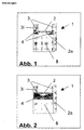
- Fig. 1 shows a cutting device (1) according to the invention consisting of a Film support surface (2) on its front side (side on which a piece of tape cut to length a cutting knife (4) is integrated on both sides.
- the knife surfaces run approximately parallel to the front of the cutting device, the knife blades are inclined at an angle between approximately 85 ° and 2 °, preferably 70 ° and 5 °, particularly preferably between 50 ° and 5 ° to the film contact surface (2). These angles apply, like other general information, regardless of the Embodiment according to Fig. 1.
- Web (3) On the side of the film support surface (2) are Web (3), which together with the base of the cutting device (5) Can accommodate cutting knife.
- the web height advantageously corresponds at least to that Height of the cutting knife on the inside of the webs (3i).
- the front edge (2a) of the Film contact surface is advantageously carried out such that the incisions when cutting into the piece of tape to be cut with the cutting knives (4) be introduced, directed in such a way that a single smooth and approximate straight cutting edge is generated, i.e. Knife cutting and leading edge lie in a line.
- Knife cutting and leading edge lie in a line.
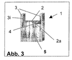
- the knife (4) can be in the form of two separate units, or also be formed from one part according to Fig. 2.
- the knife are also integrated in the same.
- Beneficial for producing a smooth The cut edge is that the connecting line between the two knife edges is in the form of an edge forwarding the incisions in the film.
- the film contact surface is preferably designed such that the adhesive film when Cut the entire surface with the sticky side resting on it.
- Self-adhesive films with e.g. B. biaxially oriented polypropylene carrier, with biaxially stretched Polyethylene terephthalate carrier, with cellulose acetate carrier or with cellophane carrier, um just to name a few, excellent cutting.
- a smooth cut edge is usually used both generated when the self-adhesive film in front of the front of the cutter is pulled downwards in the middle, i.e. without deflection to the left or to the right, or also with lateral deflection, i.e. diagonally to the left or towards is pulled to the right.
- a cutting device can also be used according to the invention only a one-sided cutting knife (4) can be used.
- the incision is made in the tape strips to be cut off on this knife.
- the incision is forwarded accordingly at the front edge (2a) of the film support surface (2), so that a smooth cutting edge over the entire width of the self-adhesive film used is produced.
- the cutting knives which can be used according to the invention can have different shapes his. Examples include triangular knife geometries with a straight knife edge. Other shapes include round knife edges or those that consist of several straight and // or round segments are constructed.
- To different adhesive films Cut the width in all cases while using rigidly fixed knives to be able to, the distance that protrudes beyond the film support surface (2) Cutting from each other may be smaller than the width of the adhesive film used.
- Knife cutting reduces the risk of injury while the knife width remains the same above the film contact surface (2) and thus enables injury-free use of knives which have a greater width above the film contact surface (2).
- Corresponding knives can preferably be used if adhesive films are different Width to be processed on a dispenser. So is at an angle of inclination the cutting edge from 30 ° up to a lateral knife height on the inside the webs (3i) of Fig. 1 of 2.5 mm should not be expected to pose a risk of injury.
- the Knife width above the film contact surface (2) in Fig. 1 is in this case in each case 5 mm.
- Knives can therefore preferably be used when the adhesive films to be processed vary widely in width. Specifically, the knives can cover the entire The width of the film contact surface is above the same.
- the distance between the cutting knives can be about the width of the cutting device can be designed so that a position Adaptation to adhesive films of different widths can be made.
- one or both of the side webs (3) can be equipped with cutting blades (4) in Fig. 1 can be arranged movably parallel to the film support surface. advantageously, can be snapped into the cutting device for simple and precise width positioning be integrated, e.g. B. for the standard adhesive film widths 12 mm, 15 mm and 19 mm.
- Cutting devices for self-adhesive films according to the invention can be used in a large range Number of dispenser types can be used. Suitable dispenser types include Table and handheld dispensers, in which the housing holding the adhesive tape roll is spatially separated from the film support and the cutting device, compact dispenser as well as transfer dispensers as previously described.
- a large number of commercially available blade knives are suitable as cutting knives.
- Typical examples include steel knife blades with preferred thicknesses between approx. 0.08 mm and 0.8 mm.
- Steels can be hardened, e.g. B. a titanium nitride coating have undergone in order to achieve increased knife service life.
- a typical grinding angle is 10 °, with suitable blade knives both can have a cut on both sides.
- the adhesive strips are removed manually from the PVC primer removed. To do this, the adhesive film strips are started from a corner detached with your fingernail, then carefully up to half the length of the adhesive film abgsc consent. The adhesive film strips are on the opposite separating edge replaced in the same way. In total, there are 20 on the 10 adhesive film strips Attempted replacement. The trials in which the Peel off the adhesive film strips from the PVC without tearing at the severed edge to let.
- a tesa table dispenser 6059 which is equipped with the cutting device to be tested is in the longitudinal direction in front of the test subject on a table.
- the subject pulled a Glovex vinyl glove (item no .: 71259) over his hand. She puts her index finger on the support surface and presses the finger with approx. 5N Pressure against the knife blade arranged on the side. Then the finger of the glove examined for cuts.
- the test is done with test subjects with a finger diameter of approx. 12 ⁇ 2 mm.
- the existing cut-off device is attached with adhesive film overlay by an aluminum cutting device replaced, which is shaped in its upper part according to Fig. 1 is.
- an adhesive film contact surface that runs parallel to the base of the adhesive tape dispenser the dimensions 20 mm * 3 mm (width * depth) border on both Side bars measuring 5 mm * 2.5 mm * 3 mm (height * width * depth).
- the leading edge the film contact surface is rectangular.
- Self-adhesive films # 1 to # 6 with a width of 19 mm are tested for cutability, structure of the cut edge and tear-free redetachment of glued adhesive film strips. The risk of injury on the cutting blades is also assessed. The following properties result:
- the cutting device according to the invention results a smooth and straight cut edge.
- All adhesive films can be used with both Cutting off to the front as well as when cutting diagonally very easily, the calender film Separate easily based on a mixture of PE and EVAc copolymer. Nearly all adhesive strips can be removed without tearing after gluing.
- the adhesive films # 1 to # 3 on the one equipped with an original knife tesa dispenser 6059 processed.
- the detachment is considered easy in all cases when cutting obliquely and as moderately difficult when cutting in the middle.
- a tear-free redetachment of glued adhesive film strips is only possible in approx. 10 up to 30% of all cases possible.
- test setups can be implemented, which reliably cut all adhesive film widths or only a part.
- Triangular knife geometries even with low angles of inclination, allow a very easy and smooth cutting of all tested adhesive film widths at the same time only little or no risk of injury if the knives come into direct contact with a finger.
- Cutting knives with regard to the film contact surface have proven to be particularly advantageous are concave.
- the tear-free removal of the self-adhesive films is through the use of non-toothed, smooth, very sharp cutting knives in the Compared to a classic dispenser knife significantly improved in all cases.
Landscapes
- Adhesive Tapes (AREA)
- Nonmetal Cutting Devices (AREA)
- Adhesive Tape Dispensing Devices (AREA)
Claims (11)
- Dévidoir de ruban adhésif avec un dispositif de coupe présentant un couteau, le dispositif de coupe (1) présentant une surface de support (2) pour le ruban adhésif (22) à couper, avec deux nervures (3) latérales pour le guidage latéral du ruban adhésif (22) sur ses deux arêtes, un couteau tranchant (4) étant disposé sur le côté intérieur d'une nervure ou des deux nervures (3), caractérisé en ce que la lame dé couteau est inclinée en biais par rapport à la surface support (2) en formant un angle, les nervures (3) étant conçues plus hautes ou de même hauteur que le ou les couteaux tranchants (4),
caractérisé en ce que
les couteaux tranchants (4) sont disposés dans la zone des nervures (3) latérales et sont protégés par ces nervures de telle sorte qu'ils ne sont pas accessibles avec un doigt au point que les doigts soient blessés,
moyennant quoi les nervures (3) latérales sont conçues de telle sorte qu'elles ne dépassent pas les couteaux tranchants (4)
et moyennant quoi l'arête (2a) avant de la surface de support (2) est disposée de telle sorte qu'elle transmet les entailles des couteaux tranchants (4) dans le ruban adhésif (22) de telle sorte qu'on obtient une arête de coupe lisse dans le ruban adhésif (22). - Dévidoir de ruban adhésif selon la revendication 1, caractérisé en ce que les couteaux tranchants (4) sont disposés sur le côté avant, c'est-à-dire le côté sur lequel on prélève un bout en suspension de ruban adhésif (22), du dispositif de coupe (5).
- Dévidoir de ruban adhésif selon la revendication 1, caractérisé en ce que les surfaces des couteaux tranchants (4) sont disposées parallèlement à la face avant du dispositif de coupe (5).
- Dévidoir de ruban adhésif selon la revendication 1, caractérisé en ce qu'un couteau tranchant (4) est disposé sur chacune des deux nervures (3).
- Dévidoir de ruban adhésif selon la revendication 1, caractérisé en ce que l'angle sous lequel les couteaux (4) sont disposés de façon inclinée par rapport à la surface de support (2) est de 85° jusqu'à 2°, en particulier de 70° à 5°, de préférence de 50° jusqu'à 5°.
- Dévidoir de ruban adhésif selon la revendication 1, caractérisé en ce que le côté avant du dispositif de coupe (5) est formé en une arête (2a) droite, avec laquelle les lames des couteaux tranchants (4) sont orientées sur une seule ligne.
- Dévidoir de ruban adhésif selon la revendication 1, caractérisé en ce que les couteaux tranchants (4) sont conçus comme des couteaux séparés ou comme un couteau d'une seule pièce.
- Dévidoir de ruban adhésif selon la revendication 1, caractérisé en ce que les couteaux tranchants (4) sont conçus dans une forme triangulaire et sont disposés respectivement sur les nervures (3) latérales.
- Dévidoir de ruban adhésif selon la revendication 1, caractérisé en ce que les couteaux tranchants (4) sont conçus dans une forme concave par rapport à la surface de support de films (2) et sont disposés respectivement sur les nervures (3) latérales.
- Dévidoir de ruban adhésif selon la revendication 1, caractérisé en ce que l'espacement des couteaux tranchants (4) est conçu avec une possibilité de positionnement les uns par rapport aux autres.
- Utilisation d'un dévidoir de ruban adhésif selon l'une quelconque des revendications 1 à 10 pour couper sans blessure des rubans adhésifs avec un support à base de film orienté dans le sens biaxial ou très étiré, en particulier à base de polyoléfine.
Applications Claiming Priority (2)
| Application Number | Priority Date | Filing Date | Title |
|---|---|---|---|
| DE19741618A DE19741618A1 (de) | 1997-09-20 | 1997-09-20 | Klebeband-Dispenser und seine Verwendung |
| DE19741618 | 1997-09-20 |
Publications (3)
| Publication Number | Publication Date |
|---|---|
| EP0903312A2 EP0903312A2 (fr) | 1999-03-24 |
| EP0903312A3 EP0903312A3 (fr) | 1999-04-28 |
| EP0903312B1 true EP0903312B1 (fr) | 2004-04-14 |
Family
ID=7843113
Family Applications (1)
| Application Number | Title | Priority Date | Filing Date |
|---|---|---|---|
| EP98117041A Expired - Lifetime EP0903312B1 (fr) | 1997-09-20 | 1998-09-09 | Distributeur de ruban adhésif et son utilisation |
Country Status (4)
| Country | Link |
|---|---|
| US (1) | US6553884B1 (fr) |
| EP (1) | EP0903312B1 (fr) |
| DE (2) | DE19741618A1 (fr) |
| ES (1) | ES2217472T3 (fr) |
Families Citing this family (6)
| Publication number | Priority date | Publication date | Assignee | Title |
|---|---|---|---|---|
| CA2513581A1 (fr) * | 2003-01-23 | 2004-08-05 | 3L-Ludvigsen A/S | Dispositif de distribution de morceaux adhesifs d'un adhesif double-face |
| US8596031B2 (en) * | 2005-05-20 | 2013-12-03 | San Jamar, Inc. | Wrap dispensing station and method |
| US9975724B2 (en) * | 2011-08-25 | 2018-05-22 | Lamus Enterprises Inc. | Tape applicator |
| USD820447S1 (en) | 2015-03-23 | 2018-06-12 | Sparo, Inc. | Spirometer device |
| US12005651B2 (en) | 2020-11-20 | 2024-06-11 | Intertape Polymer Corp. | Tape applicator with split wiper |
| CN117140943B (zh) * | 2023-10-30 | 2024-02-13 | 山东普克汽车饰件有限公司 | 一种汽车内饰件覆膜裁切装置 |
Family Cites Families (18)
| Publication number | Priority date | Publication date | Assignee | Title |
|---|---|---|---|---|
| US2540697A (en) * | 1948-08-06 | 1951-02-06 | George E Staples | Tape dispenser |
| GB765497A (en) * | 1953-11-10 | 1957-01-09 | Johnson & Johnson | Cutting device |
| GB765496A (en) | 1953-11-19 | 1957-01-09 | Baldwin Lima Hamilton Corp | Billet container for metal extrusion presses |
| US2992582A (en) * | 1958-03-31 | 1961-07-18 | Johnson & Johnson | Pressure-sensitive tape dispenser |
| DE1083153B (de) * | 1958-09-17 | 1960-06-09 | Claus Koenig G M B H | Klebeband-Abroller mit Anlegetisch und geradlinig trennender Schneidvorrichtung |
| DE1085440B (de) * | 1959-10-23 | 1960-07-14 | Claus Koenig G M B H | Klebeband-Abroller mit Anlegetisch und geradlinig trennender Schneidvorrichtung |
| US3050853A (en) * | 1960-09-26 | 1962-08-28 | Crane Packing Co | Tape dispenser |
| US3470781A (en) * | 1967-04-21 | 1969-10-07 | Crane Packing Co | Positive feed device for tape dispenser |
| US3508692A (en) * | 1968-06-10 | 1970-04-28 | Victor E Holtan | Tape dispenser and cutter |
| US3635473A (en) * | 1968-10-10 | 1972-01-18 | Sekisui Adoheya Kogya Kk | Tape cutter |
| CH532525A (de) * | 1970-12-17 | 1973-01-15 | Hansjoerg Dipl Ch Rothenberger | Gerät zum Aufbringen eines Selbstklebebandes |
| US4196647A (en) * | 1978-08-15 | 1980-04-08 | Reynolds Metals Company | Carton for dispensing and cutting sheet material |
| US4244254A (en) * | 1979-08-17 | 1981-01-13 | Reynolds Metals Company | Carton for cutting and dispensing sheet material |
| US4608894A (en) * | 1983-02-09 | 1986-09-02 | Lee Ki S | Adhesive tape-cutting device |
| DE8904789U1 (de) * | 1989-04-17 | 1989-08-10 | Steuer, Herbert, 6380 Bad Homburg | Schneidvorrichtung für Bänder an Abrollgeräten |
| FR2656601B1 (fr) * | 1989-12-28 | 1992-04-24 | Maurice Granger | Appareil de distribution et de coupe simultanees de bandes de materiaux enroules. |
| US5146828A (en) * | 1991-03-29 | 1992-09-15 | Huang Hong Yuan | Wrap film cutter |
| US5678689A (en) * | 1995-08-22 | 1997-10-21 | Clark; Mary J. | Two side taping apparatus |
-
1997
- 1997-09-20 DE DE19741618A patent/DE19741618A1/de not_active Ceased
-
1998
- 1998-09-09 ES ES98117041T patent/ES2217472T3/es not_active Expired - Lifetime
- 1998-09-09 DE DE59811180T patent/DE59811180D1/de not_active Expired - Lifetime
- 1998-09-09 EP EP98117041A patent/EP0903312B1/fr not_active Expired - Lifetime
- 1998-09-16 US US09/154,123 patent/US6553884B1/en not_active Expired - Fee Related
Also Published As
| Publication number | Publication date |
|---|---|
| DE59811180D1 (de) | 2004-05-19 |
| DE19741618A1 (de) | 1999-04-01 |
| EP0903312A2 (fr) | 1999-03-24 |
| US6553884B1 (en) | 2003-04-29 |
| EP0903312A3 (fr) | 1999-04-28 |
| ES2217472T3 (es) | 2004-11-01 |
Similar Documents
| Publication | Publication Date | Title |
|---|---|---|
| DE69721973T2 (de) | Schneidegerät | |
| EP0705769B1 (fr) | Emballage pour couteaux et objets analogues | |
| EP0640236B1 (fr) | Feuille d'etiquettes, procede et dispositif permettant de produire une telle feuille d'etiquettes | |
| EP0696628A2 (fr) | Ruban adhésif | |
| DE69915707T2 (de) | Sicherheitsschneidmessereinheit | |
| DE69805636T2 (de) | Schneidemesser zum zerissen von blattmaterialien | |
| DE1594179C3 (de) | Von Hand abreißbares Selbstklebeband und Verfahren zu seiner Herstellung | |
| DE4318277C1 (de) | Verwendung von Zackenschnittmessern | |
| EP0903312B1 (fr) | Distributeur de ruban adhésif et son utilisation | |
| EP2766287B1 (fr) | Dérouleur | |
| EP0233281B1 (fr) | Distributeur avec dispositif de coupe | |
| DE102009033575A1 (de) | Folienmesser mit Saugkammer | |
| DE102011079544B4 (de) | Abroller | |
| EP0332072A2 (fr) | Emballage pour objets, particulièrement en forme de parallélépipède | |
| WO2009030491A1 (fr) | Dispositif et procédé de guidage d'une bande de matière | |
| GB2389356A (en) | A disposable package and cutting apparatus | |
| DE19641094C1 (de) | Verfahren zum verlustfreien Stanzen von klebenden Stanzlingen | |
| EP0943545B1 (fr) | Lame de coupe pour un distributeur de ruban adhésif | |
| DE29821829U1 (de) | Klebeband-Dispenser und seine Verwendung | |
| DE202018102992U1 (de) | Aufnahmeeinheit für Frischhaltefolien | |
| EP0714845B1 (fr) | Dispositif portable à coupe transversale pour couper des rubans adhésifs | |
| DE10355901B4 (de) | Nachfüllbarer Spender für Papier- und/oder Folienrollen | |
| EP4313596B1 (fr) | Procédé de production d'un film composite adhésif | |
| JP3246869B2 (ja) | シート状未硬化コンパウンドの打ち抜き方法及びその方法に用いる打ち抜き用治具 | |
| EP1792863B1 (fr) | Dispositif séparateur pour bandes |
Legal Events
| Date | Code | Title | Description |
|---|---|---|---|
| PUAI | Public reference made under article 153(3) epc to a published international application that has entered the european phase |
Free format text: ORIGINAL CODE: 0009012 |
|
| PUAL | Search report despatched |
Free format text: ORIGINAL CODE: 0009013 |
|
| AK | Designated contracting states |
Kind code of ref document: A2 Designated state(s): DE ES FR GB IT |
|
| AX | Request for extension of the european patent |
Free format text: AL;LT;LV;MK;RO;SI |
|
| AK | Designated contracting states |
Kind code of ref document: A3 Designated state(s): AT BE CH CY DE DK ES FI FR GB GR IE IT LI LU MC NL PT SE |
|
| AX | Request for extension of the european patent |
Free format text: AL;LT;LV;MK;RO;SI |
|
| 17P | Request for examination filed |
Effective date: 19990401 |
|
| AKX | Designation fees paid |
Free format text: DE ES FR GB IT |
|
| RAP1 | Party data changed (applicant data changed or rights of an application transferred) |
Owner name: TESA AG |
|
| 17Q | First examination report despatched |
Effective date: 20020207 |
|
| GRAP | Despatch of communication of intention to grant a patent |
Free format text: ORIGINAL CODE: EPIDOSNIGR1 |
|
| RIN1 | Information on inventor provided before grant (corrected) |
Inventor name: KUBASCH, PETER Inventor name: NEUMANN, UWE Inventor name: LINDE, HANSJUERGEN, PROF. DR. Inventor name: HAZES, HANS Inventor name: REHKLAU ANDREAS Inventor name: LEIBER, JOERN, DR. Inventor name: SCHLIEPHACKE, RALF Inventor name: LUEHMANN, BERND, DR. |
|
| GRAS | Grant fee paid |
Free format text: ORIGINAL CODE: EPIDOSNIGR3 |
|
| GRAA | (expected) grant |
Free format text: ORIGINAL CODE: 0009210 |
|
| AK | Designated contracting states |
Kind code of ref document: B1 Designated state(s): DE ES FR GB IT |
|
| REG | Reference to a national code |
Ref country code: GB Ref legal event code: FG4D Free format text: NOT ENGLISH |
|
| REF | Corresponds to: |
Ref document number: 59811180 Country of ref document: DE Date of ref document: 20040519 Kind code of ref document: P |
|
| GBT | Gb: translation of ep patent filed (gb section 77(6)(a)/1977) |
Effective date: 20040602 |
|
| RAP2 | Party data changed (patent owner data changed or rights of a patent transferred) |
Owner name: TESA AG |
|
| REG | Reference to a national code |
Ref country code: ES Ref legal event code: FG2A Ref document number: 2217472 Country of ref document: ES Kind code of ref document: T3 |
|
| ET | Fr: translation filed | ||
| PLBE | No opposition filed within time limit |
Free format text: ORIGINAL CODE: 0009261 |
|
| STAA | Information on the status of an ep patent application or granted ep patent |
Free format text: STATUS: NO OPPOSITION FILED WITHIN TIME LIMIT |
|
| 26N | No opposition filed |
Effective date: 20050117 |
|
| PGFP | Annual fee paid to national office [announced via postgrant information from national office to epo] |
Ref country code: ES Payment date: 20090922 Year of fee payment: 12 |
|
| PGFP | Annual fee paid to national office [announced via postgrant information from national office to epo] |
Ref country code: GB Payment date: 20090922 Year of fee payment: 12 |
|
| REG | Reference to a national code |
Ref country code: FR Ref legal event code: CJ Ref country code: FR Ref legal event code: CD |
|
| PGFP | Annual fee paid to national office [announced via postgrant information from national office to epo] |
Ref country code: IT Payment date: 20090925 Year of fee payment: 12 |
|
| GBPC | Gb: european patent ceased through non-payment of renewal fee |
Effective date: 20100909 |
|
| PG25 | Lapsed in a contracting state [announced via postgrant information from national office to epo] |
Ref country code: IT Free format text: LAPSE BECAUSE OF NON-PAYMENT OF DUE FEES Effective date: 20100909 |
|
| PG25 | Lapsed in a contracting state [announced via postgrant information from national office to epo] |
Ref country code: GB Free format text: LAPSE BECAUSE OF NON-PAYMENT OF DUE FEES Effective date: 20100909 |
|
| REG | Reference to a national code |
Ref country code: ES Ref legal event code: FD2A Effective date: 20111019 |
|
| PG25 | Lapsed in a contracting state [announced via postgrant information from national office to epo] |
Ref country code: ES Free format text: LAPSE BECAUSE OF NON-PAYMENT OF DUE FEES Effective date: 20100910 |
|
| PGFP | Annual fee paid to national office [announced via postgrant information from national office to epo] |
Ref country code: DE Payment date: 20130930 Year of fee payment: 16 |
|
| PGFP | Annual fee paid to national office [announced via postgrant information from national office to epo] |
Ref country code: FR Payment date: 20130919 Year of fee payment: 16 |
|
| REG | Reference to a national code |
Ref country code: DE Ref legal event code: R119 Ref document number: 59811180 Country of ref document: DE |
|
| REG | Reference to a national code |
Ref country code: DE Ref legal event code: R119 Ref document number: 59811180 Country of ref document: DE Effective date: 20150401 |
|
| REG | Reference to a national code |
Ref country code: FR Ref legal event code: ST Effective date: 20150529 |
|
| PG25 | Lapsed in a contracting state [announced via postgrant information from national office to epo] |
Ref country code: DE Free format text: LAPSE BECAUSE OF NON-PAYMENT OF DUE FEES Effective date: 20150401 |
|
| PG25 | Lapsed in a contracting state [announced via postgrant information from national office to epo] |
Ref country code: FR Free format text: LAPSE BECAUSE OF NON-PAYMENT OF DUE FEES Effective date: 20140930 |