EP0903312B1 - Adhesive tape dispenser and use thereof - Google Patents
Adhesive tape dispenser and use thereof Download PDFInfo
- Publication number
- EP0903312B1 EP0903312B1 EP98117041A EP98117041A EP0903312B1 EP 0903312 B1 EP0903312 B1 EP 0903312B1 EP 98117041 A EP98117041 A EP 98117041A EP 98117041 A EP98117041 A EP 98117041A EP 0903312 B1 EP0903312 B1 EP 0903312B1
- Authority
- EP
- European Patent Office
- Prior art keywords
- cutting
- adhesive tape
- knife
- adhesive
- blades
- Prior art date
- Legal status (The legal status is an assumption and is not a legal conclusion. Google has not performed a legal analysis and makes no representation as to the accuracy of the status listed.)
- Expired - Lifetime
Links
- 239000002390 adhesive tape Substances 0.000 title claims description 48
- 238000005520 cutting process Methods 0.000 claims description 103
- 230000006378 damage Effects 0.000 claims description 23
- 208000027418 Wounds and injury Diseases 0.000 claims description 20
- 208000014674 injury Diseases 0.000 claims description 20
- 230000000284 resting effect Effects 0.000 claims description 7
- 229920000098 polyolefin Polymers 0.000 claims description 2
- 239000002313 adhesive film Substances 0.000 description 66
- 238000012360 testing method Methods 0.000 description 7
- 239000000853 adhesive Substances 0.000 description 5
- 230000001070 adhesive effect Effects 0.000 description 5
- 239000000463 material Substances 0.000 description 5
- 229910000831 Steel Inorganic materials 0.000 description 4
- 239000010959 steel Substances 0.000 description 4
- -1 Polypropylen Polymers 0.000 description 3
- 239000004743 Polypropylene Substances 0.000 description 3
- 239000000969 carrier Substances 0.000 description 3
- 238000012545 processing Methods 0.000 description 3
- 230000001681 protective effect Effects 0.000 description 3
- 229920006378 biaxially oriented polypropylene Polymers 0.000 description 2
- 239000011127 biaxially oriented polypropylene Substances 0.000 description 2
- 230000015572 biosynthetic process Effects 0.000 description 2
- 238000002474 experimental method Methods 0.000 description 2
- 239000002655 kraft paper Substances 0.000 description 2
- 229910052751 metal Inorganic materials 0.000 description 2
- 239000002184 metal Substances 0.000 description 2
- 239000004033 plastic Substances 0.000 description 2
- 229920003023 plastic Polymers 0.000 description 2
- 229920000139 polyethylene terephthalate Polymers 0.000 description 2
- 239000005020 polyethylene terephthalate Substances 0.000 description 2
- 229920001155 polypropylene Polymers 0.000 description 2
- 230000001012 protector Effects 0.000 description 2
- 238000012546 transfer Methods 0.000 description 2
- 206010003830 Automatism Diseases 0.000 description 1
- 229920000298 Cellophane Polymers 0.000 description 1
- 241000985128 Cladium mariscus Species 0.000 description 1
- 208000012880 Finger injury Diseases 0.000 description 1
- 241001295925 Gegenes Species 0.000 description 1
- 239000004698 Polyethylene Substances 0.000 description 1
- NRTOMJZYCJJWKI-UHFFFAOYSA-N Titanium nitride Chemical compound [Ti]#N NRTOMJZYCJJWKI-UHFFFAOYSA-N 0.000 description 1
- 230000006978 adaptation Effects 0.000 description 1
- 238000004026 adhesive bonding Methods 0.000 description 1
- 229910052782 aluminium Inorganic materials 0.000 description 1
- XAGFODPZIPBFFR-UHFFFAOYSA-N aluminium Chemical compound [Al] XAGFODPZIPBFFR-UHFFFAOYSA-N 0.000 description 1
- 230000009286 beneficial effect Effects 0.000 description 1
- YFXPPSKYMBTNAV-UHFFFAOYSA-N bensultap Chemical compound C=1C=CC=CC=1S(=O)(=O)SCC(N(C)C)CSS(=O)(=O)C1=CC=CC=C1 YFXPPSKYMBTNAV-UHFFFAOYSA-N 0.000 description 1
- 239000012876 carrier material Substances 0.000 description 1
- 229920002301 cellulose acetate Polymers 0.000 description 1
- 239000011248 coating agent Substances 0.000 description 1
- 238000000576 coating method Methods 0.000 description 1
- 229920001577 copolymer Polymers 0.000 description 1
- 210000004905 finger nail Anatomy 0.000 description 1
- 229920001519 homopolymer Polymers 0.000 description 1
- 238000002347 injection Methods 0.000 description 1
- 239000007924 injection Substances 0.000 description 1
- 238000001746 injection moulding Methods 0.000 description 1
- 230000010354 integration Effects 0.000 description 1
- 238000004519 manufacturing process Methods 0.000 description 1
- 238000000034 method Methods 0.000 description 1
- 239000000203 mixture Substances 0.000 description 1
- WXZMFSXDPGVJKK-UHFFFAOYSA-N pentaerythritol Chemical compound OCC(CO)(CO)CO WXZMFSXDPGVJKK-UHFFFAOYSA-N 0.000 description 1
- 239000007858 starting material Substances 0.000 description 1
- 238000003860 storage Methods 0.000 description 1
- 239000000758 substrate Substances 0.000 description 1
- 238000010998 test method Methods 0.000 description 1
- 125000000391 vinyl group Chemical group [H]C([*])=C([H])[H] 0.000 description 1
- 229920002554 vinyl polymer Polymers 0.000 description 1
Images
Classifications
-
- B—PERFORMING OPERATIONS; TRANSPORTING
- B65—CONVEYING; PACKING; STORING; HANDLING THIN OR FILAMENTARY MATERIAL
- B65H—HANDLING THIN OR FILAMENTARY MATERIAL, e.g. SHEETS, WEBS, CABLES
- B65H35/00—Delivering articles from cutting or line-perforating machines; Article or web delivery apparatus incorporating cutting or line-perforating devices, e.g. adhesive tape dispensers
- B65H35/0006—Article or web delivery apparatus incorporating cutting or line-perforating devices
- B65H35/002—Hand-held or table apparatus
- B65H35/0026—Hand-held or table apparatus for delivering pressure-sensitive adhesive tape
-
- B—PERFORMING OPERATIONS; TRANSPORTING
- B65—CONVEYING; PACKING; STORING; HANDLING THIN OR FILAMENTARY MATERIAL
- B65H—HANDLING THIN OR FILAMENTARY MATERIAL, e.g. SHEETS, WEBS, CABLES
- B65H35/00—Delivering articles from cutting or line-perforating machines; Article or web delivery apparatus incorporating cutting or line-perforating devices, e.g. adhesive tape dispensers
- B65H35/0006—Article or web delivery apparatus incorporating cutting or line-perforating devices
- B65H35/0073—Details
- B65H35/008—Arrangements or adaptations of cutting devices
-
- Y—GENERAL TAGGING OF NEW TECHNOLOGICAL DEVELOPMENTS; GENERAL TAGGING OF CROSS-SECTIONAL TECHNOLOGIES SPANNING OVER SEVERAL SECTIONS OF THE IPC; TECHNICAL SUBJECTS COVERED BY FORMER USPC CROSS-REFERENCE ART COLLECTIONS [XRACs] AND DIGESTS
- Y10—TECHNICAL SUBJECTS COVERED BY FORMER USPC
- Y10T—TECHNICAL SUBJECTS COVERED BY FORMER US CLASSIFICATION
- Y10T156/00—Adhesive bonding and miscellaneous chemical manufacture
- Y10T156/17—Surface bonding means and/or assemblymeans with work feeding or handling means
- Y10T156/1788—Work traversing type and/or means applying work to wall or static structure
- Y10T156/1795—Implement carried web supply
-
- Y—GENERAL TAGGING OF NEW TECHNOLOGICAL DEVELOPMENTS; GENERAL TAGGING OF CROSS-SECTIONAL TECHNOLOGIES SPANNING OVER SEVERAL SECTIONS OF THE IPC; TECHNICAL SUBJECTS COVERED BY FORMER USPC CROSS-REFERENCE ART COLLECTIONS [XRACs] AND DIGESTS
- Y10—TECHNICAL SUBJECTS COVERED BY FORMER USPC
- Y10T—TECHNICAL SUBJECTS COVERED BY FORMER US CLASSIFICATION
- Y10T225/00—Severing by tearing or breaking
- Y10T225/20—Severing by manually forcing against fixed edge
- Y10T225/205—With feed-out of predetermined length from work supply
- Y10T225/206—Including means to select or adjust feed-out length
-
- Y—GENERAL TAGGING OF NEW TECHNOLOGICAL DEVELOPMENTS; GENERAL TAGGING OF CROSS-SECTIONAL TECHNOLOGIES SPANNING OVER SEVERAL SECTIONS OF THE IPC; TECHNICAL SUBJECTS COVERED BY FORMER USPC CROSS-REFERENCE ART COLLECTIONS [XRACs] AND DIGESTS
- Y10—TECHNICAL SUBJECTS COVERED BY FORMER USPC
- Y10T—TECHNICAL SUBJECTS COVERED BY FORMER US CLASSIFICATION
- Y10T225/00—Severing by tearing or breaking
- Y10T225/20—Severing by manually forcing against fixed edge
- Y10T225/205—With feed-out of predetermined length from work supply
- Y10T225/207—Including feed-out stop for manually pulled work
- Y10T225/209—With feed-out of lead-end to aid initial grasping
-
- Y—GENERAL TAGGING OF NEW TECHNOLOGICAL DEVELOPMENTS; GENERAL TAGGING OF CROSS-SECTIONAL TECHNOLOGIES SPANNING OVER SEVERAL SECTIONS OF THE IPC; TECHNICAL SUBJECTS COVERED BY FORMER USPC CROSS-REFERENCE ART COLLECTIONS [XRACs] AND DIGESTS
- Y10—TECHNICAL SUBJECTS COVERED BY FORMER USPC
- Y10T—TECHNICAL SUBJECTS COVERED BY FORMER US CLASSIFICATION
- Y10T225/00—Severing by tearing or breaking
- Y10T225/20—Severing by manually forcing against fixed edge
- Y10T225/205—With feed-out of predetermined length from work supply
- Y10T225/21—Merely to provide lead-end for manual grasping
-
- Y—GENERAL TAGGING OF NEW TECHNOLOGICAL DEVELOPMENTS; GENERAL TAGGING OF CROSS-SECTIONAL TECHNOLOGIES SPANNING OVER SEVERAL SECTIONS OF THE IPC; TECHNICAL SUBJECTS COVERED BY FORMER USPC CROSS-REFERENCE ART COLLECTIONS [XRACs] AND DIGESTS
- Y10—TECHNICAL SUBJECTS COVERED BY FORMER USPC
- Y10T—TECHNICAL SUBJECTS COVERED BY FORMER US CLASSIFICATION
- Y10T225/00—Severing by tearing or breaking
- Y10T225/20—Severing by manually forcing against fixed edge
- Y10T225/205—With feed-out of predetermined length from work supply
- Y10T225/211—Manually operated feed-out mechanism
-
- Y—GENERAL TAGGING OF NEW TECHNOLOGICAL DEVELOPMENTS; GENERAL TAGGING OF CROSS-SECTIONAL TECHNOLOGIES SPANNING OVER SEVERAL SECTIONS OF THE IPC; TECHNICAL SUBJECTS COVERED BY FORMER USPC CROSS-REFERENCE ART COLLECTIONS [XRACs] AND DIGESTS
- Y10—TECHNICAL SUBJECTS COVERED BY FORMER USPC
- Y10T—TECHNICAL SUBJECTS COVERED BY FORMER US CLASSIFICATION
- Y10T83/00—Cutting
- Y10T83/647—With means to convey work relative to tool station
- Y10T83/664—Roller
- Y10T83/6644—With work-supplying reel
-
- Y—GENERAL TAGGING OF NEW TECHNOLOGICAL DEVELOPMENTS; GENERAL TAGGING OF CROSS-SECTIONAL TECHNOLOGIES SPANNING OVER SEVERAL SECTIONS OF THE IPC; TECHNICAL SUBJECTS COVERED BY FORMER USPC CROSS-REFERENCE ART COLLECTIONS [XRACs] AND DIGESTS
- Y10—TECHNICAL SUBJECTS COVERED BY FORMER USPC
- Y10T—TECHNICAL SUBJECTS COVERED BY FORMER US CLASSIFICATION
- Y10T83/00—Cutting
- Y10T83/727—With means to guide moving work
- Y10T83/739—Positively confines or otherwise determines path of work
-
- Y—GENERAL TAGGING OF NEW TECHNOLOGICAL DEVELOPMENTS; GENERAL TAGGING OF CROSS-SECTIONAL TECHNOLOGIES SPANNING OVER SEVERAL SECTIONS OF THE IPC; TECHNICAL SUBJECTS COVERED BY FORMER USPC CROSS-REFERENCE ART COLLECTIONS [XRACs] AND DIGESTS
- Y10—TECHNICAL SUBJECTS COVERED BY FORMER USPC
- Y10T—TECHNICAL SUBJECTS COVERED BY FORMER US CLASSIFICATION
- Y10T83/00—Cutting
- Y10T83/869—Means to drive or to guide tool
- Y10T83/8798—With simple oscillating motion only
- Y10T83/8817—Axially entending cutting edge
- Y10T83/8818—Axially progressing cut
-
- Y—GENERAL TAGGING OF NEW TECHNOLOGICAL DEVELOPMENTS; GENERAL TAGGING OF CROSS-SECTIONAL TECHNOLOGIES SPANNING OVER SEVERAL SECTIONS OF THE IPC; TECHNICAL SUBJECTS COVERED BY FORMER USPC CROSS-REFERENCE ART COLLECTIONS [XRACs] AND DIGESTS
- Y10—TECHNICAL SUBJECTS COVERED BY FORMER USPC
- Y10T—TECHNICAL SUBJECTS COVERED BY FORMER US CLASSIFICATION
- Y10T83/00—Cutting
- Y10T83/889—Tool with either work holder or means to hold work supply
- Y10T83/896—Rotatable wound package supply
Definitions
- the invention relates to an adhesive tape dispenser with a knife Cutting device and its use for the injury-free cutting of Tapes.
- a disadvantage of dispensers with toothed cutting knives is that in particular self-adhesive films, which carrier materials with low tear resistance and low ductility use, cannot be detached tear-free from many reasons for detention.
- a dispenser knife with toothed Cutting edge becomes the tooth structure on the when cutting an adhesive film strip Cut edge of the cut tape shown. Through the serrated knife edge as well as any sharp burrs or damage present in the knife very fine tears in the cut edges of the adhesive film strips obtained are very common generated.
- Adhesive film strips cut to length with the tesa table dispenser 6082 who use a biaxially oriented PP carrier, e.g. B. tesa multi-film or tesa Practic-Film, can be removed without tearing in almost all cases. injury especially the fingers when using the aforementioned dispensers not be ruled out.
- US 4,175,685 describes an adhesive tape dispenser which uses a cutting unit containing razor blades. To protect against injury a flexible thread-like material spirally wrapped around the knife. Between the razor blade edge is accessible to individual spiral turns. A cross cutting smooth knife integrated in a knife bar is in the tesa industrial table dispenser 6080 used. Due to the special arrangement and orientation of the Cutting knife below the knife bar is a risk of injury to the user largely excluded.
- the diagonally to the plane of the tape to be cut Running knife edge also allows the adhesive tape to be cut easily.
- the tesa automat 6056 also uses an one that runs diagonally to the adhesive tape Knife, which is controlled electromagnetically. A risk of injury to the Users with the cutting knife are also largely excluded.
- a disadvantage of the aforementioned tape dispensers with smooth, straight knife edges high sharpness is the increased risk of injury to the cutting edges when there is no protective cover and that for processing the adhesive film by manually removing or moving a knife protection cover Operations are necessary.
- Approved cutting knife is an often complex mechanical structure of the adhesive tape dispenser, the manufacturing costs and size of the devices increased and can also reduce the functionality.
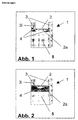
- Fig. 1 shows a cutting device (1) according to the invention consisting of a Film support surface (2) on its front side (side on which a piece of tape cut to length a cutting knife (4) is integrated on both sides.
- the knife surfaces run approximately parallel to the front of the cutting device, the knife blades are inclined at an angle between approximately 85 ° and 2 °, preferably 70 ° and 5 °, particularly preferably between 50 ° and 5 ° to the film contact surface (2). These angles apply, like other general information, regardless of the Embodiment according to Fig. 1.
- Web (3) On the side of the film support surface (2) are Web (3), which together with the base of the cutting device (5) Can accommodate cutting knife.
- the web height advantageously corresponds at least to that Height of the cutting knife on the inside of the webs (3i).
- the front edge (2a) of the Film contact surface is advantageously carried out such that the incisions when cutting into the piece of tape to be cut with the cutting knives (4) be introduced, directed in such a way that a single smooth and approximate straight cutting edge is generated, i.e. Knife cutting and leading edge lie in a line.
- Knife cutting and leading edge lie in a line.
- the knife (4) can be in the form of two separate units, or also be formed from one part according to Fig. 2.
- the knife are also integrated in the same.
- Beneficial for producing a smooth The cut edge is that the connecting line between the two knife edges is in the form of an edge forwarding the incisions in the film.
- the film contact surface is preferably designed such that the adhesive film when Cut the entire surface with the sticky side resting on it.
- Self-adhesive films with e.g. B. biaxially oriented polypropylene carrier, with biaxially stretched Polyethylene terephthalate carrier, with cellulose acetate carrier or with cellophane carrier, um just to name a few, excellent cutting.
- a smooth cut edge is usually used both generated when the self-adhesive film in front of the front of the cutter is pulled downwards in the middle, i.e. without deflection to the left or to the right, or also with lateral deflection, i.e. diagonally to the left or towards is pulled to the right.
- a cutting device can also be used according to the invention only a one-sided cutting knife (4) can be used.
- the incision is made in the tape strips to be cut off on this knife.
- the incision is forwarded accordingly at the front edge (2a) of the film support surface (2), so that a smooth cutting edge over the entire width of the self-adhesive film used is produced.
- the cutting knives which can be used according to the invention can have different shapes his. Examples include triangular knife geometries with a straight knife edge. Other shapes include round knife edges or those that consist of several straight and // or round segments are constructed.
- To different adhesive films Cut the width in all cases while using rigidly fixed knives to be able to, the distance that protrudes beyond the film support surface (2) Cutting from each other may be smaller than the width of the adhesive film used.
- Knife cutting reduces the risk of injury while the knife width remains the same above the film contact surface (2) and thus enables injury-free use of knives which have a greater width above the film contact surface (2).
- Corresponding knives can preferably be used if adhesive films are different Width to be processed on a dispenser. So is at an angle of inclination the cutting edge from 30 ° up to a lateral knife height on the inside the webs (3i) of Fig. 1 of 2.5 mm should not be expected to pose a risk of injury.
- the Knife width above the film contact surface (2) in Fig. 1 is in this case in each case 5 mm.
- Knives can therefore preferably be used when the adhesive films to be processed vary widely in width. Specifically, the knives can cover the entire The width of the film contact surface is above the same.
- the distance between the cutting knives can be about the width of the cutting device can be designed so that a position Adaptation to adhesive films of different widths can be made.
- one or both of the side webs (3) can be equipped with cutting blades (4) in Fig. 1 can be arranged movably parallel to the film support surface. advantageously, can be snapped into the cutting device for simple and precise width positioning be integrated, e.g. B. for the standard adhesive film widths 12 mm, 15 mm and 19 mm.
- Cutting devices for self-adhesive films according to the invention can be used in a large range Number of dispenser types can be used. Suitable dispenser types include Table and handheld dispensers, in which the housing holding the adhesive tape roll is spatially separated from the film support and the cutting device, compact dispenser as well as transfer dispensers as previously described.
- a large number of commercially available blade knives are suitable as cutting knives.
- Typical examples include steel knife blades with preferred thicknesses between approx. 0.08 mm and 0.8 mm.
- Steels can be hardened, e.g. B. a titanium nitride coating have undergone in order to achieve increased knife service life.
- a typical grinding angle is 10 °, with suitable blade knives both can have a cut on both sides.
- the adhesive strips are removed manually from the PVC primer removed. To do this, the adhesive film strips are started from a corner detached with your fingernail, then carefully up to half the length of the adhesive film abgsc consent. The adhesive film strips are on the opposite separating edge replaced in the same way. In total, there are 20 on the 10 adhesive film strips Attempted replacement. The trials in which the Peel off the adhesive film strips from the PVC without tearing at the severed edge to let.
- a tesa table dispenser 6059 which is equipped with the cutting device to be tested is in the longitudinal direction in front of the test subject on a table.
- the subject pulled a Glovex vinyl glove (item no .: 71259) over his hand. She puts her index finger on the support surface and presses the finger with approx. 5N Pressure against the knife blade arranged on the side. Then the finger of the glove examined for cuts.
- the test is done with test subjects with a finger diameter of approx. 12 ⁇ 2 mm.
- the existing cut-off device is attached with adhesive film overlay by an aluminum cutting device replaced, which is shaped in its upper part according to Fig. 1 is.
- an adhesive film contact surface that runs parallel to the base of the adhesive tape dispenser the dimensions 20 mm * 3 mm (width * depth) border on both Side bars measuring 5 mm * 2.5 mm * 3 mm (height * width * depth).
- the leading edge the film contact surface is rectangular.
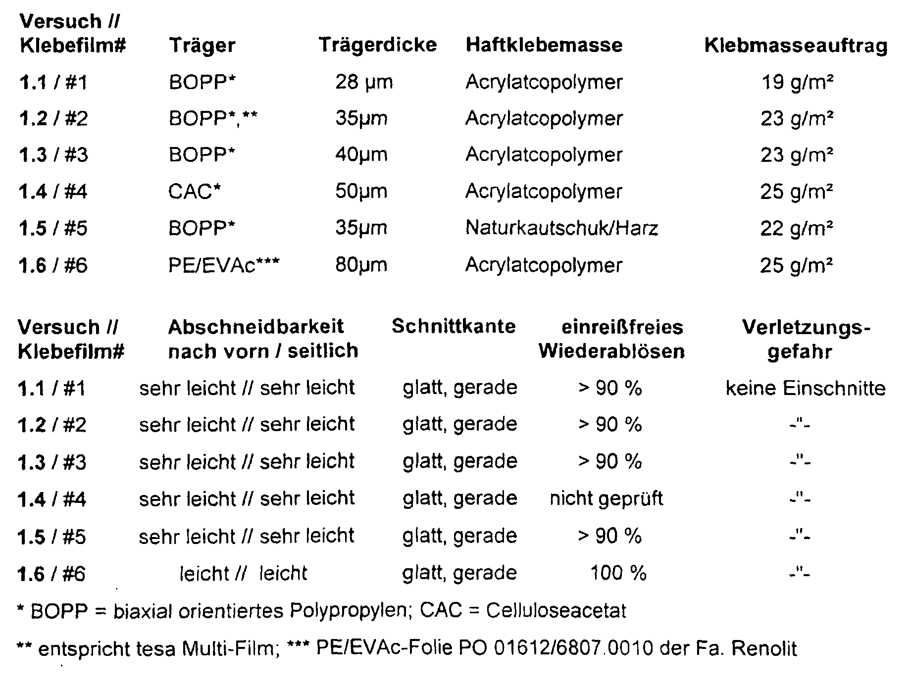
- Self-adhesive films # 1 to # 6 with a width of 19 mm are tested for cutability, structure of the cut edge and tear-free redetachment of glued adhesive film strips. The risk of injury on the cutting blades is also assessed. The following properties result:
- the cutting device according to the invention results a smooth and straight cut edge.
- All adhesive films can be used with both Cutting off to the front as well as when cutting diagonally very easily, the calender film Separate easily based on a mixture of PE and EVAc copolymer. Nearly all adhesive strips can be removed without tearing after gluing.
- the adhesive films # 1 to # 3 on the one equipped with an original knife tesa dispenser 6059 processed.
- the detachment is considered easy in all cases when cutting obliquely and as moderately difficult when cutting in the middle.
- a tear-free redetachment of glued adhesive film strips is only possible in approx. 10 up to 30% of all cases possible.
- test setups can be implemented, which reliably cut all adhesive film widths or only a part.
- Triangular knife geometries even with low angles of inclination, allow a very easy and smooth cutting of all tested adhesive film widths at the same time only little or no risk of injury if the knives come into direct contact with a finger.
- Cutting knives with regard to the film contact surface have proven to be particularly advantageous are concave.
- the tear-free removal of the self-adhesive films is through the use of non-toothed, smooth, very sharp cutting knives in the Compared to a classic dispenser knife significantly improved in all cases.
Landscapes
- Adhesive Tapes (AREA)
- Nonmetal Cutting Devices (AREA)
- Adhesive Tape Dispensing Devices (AREA)
Description
Die Erfindung betrifft einen Klebeband-Dispenser mit einer ein Messer aufweisenden Abschneidevorrichtung sowie seine Verwendung zum verletzungsfreien Abschneiden von Klebebändern.The invention relates to an adhesive tape dispenser with a knife Cutting device and its use for the injury-free cutting of Tapes.
Abroller für Klebebandrollen, auch Dispenser genannt, dienen dem Anwender als Vorratsbehältnis für die Klebebandrollen selbst sowie als Applikationshilfe für ihre Verarbeitung. Vorrangige Aufgabe eines Klebebanddispensers ist das einfache, leichte und saubere Ablängen und Zuschneiden von Klebebandstreifen in der für die vorgesehene Anwendung benötigten Länge. Typische Ausführungsformen von Dispensern umfassen als Grundelemente ein tragendes Gehäuse, eine Rollenkernaufnahme, eine Klebebandauflage und eine Abschneide- oder Abreißvorrichtung. Als wesentliche Ausführungsformen lassen sich unterscheiden:
- Dispenser von zumeist sehr kompakter Gestalt (nachfolgend auch als Kompaktdispenser bezeichnet), bestehend aus einem offenen oder geschlossenen Gehäuse, welches in seitlicher Ansicht zum Beispiel rund, trapezförmig, rechteckig oder polygonisch geformt sein kann. Die Klebebandrolle wird zur Nutzung auf einen zumeist zylinderförmigen Kernaufnehmer aufgebracht, der etwa mittig im Gehäuse integriert ist. Seitlich enthält der Dispenser einen schlitzartigen Austrittsspalt aus dem das Klebeband zum Ablängen herausgezogen wird. Üblicherweise befindet sich auf der einen Seite des Austrittsschlitzes das Schneidmesser über das ein Klebebandstück gewünschter Länge abgeschnitten werden kann. Die dem Schneidmesser gegenüberliegende Seite des Austrittsschlitzes ist zumeist als Aufnahmefläche für die haftklebrige Klebebandseite gedacht.
- Dispenser bei denen das die Klebebandrolle aufnehmende, offen oder auch geschlossen ausgeführte Gehäuse von den Elementen Klebefilmauflage und Schneidmesser räumlich getrennt ist. Entsprechende Dispenser finden als Hand- und als Tischdispenser breite Anwendung. Sie bieten bei verringerter Kompaktheit den Vorteil, daß Klebeband schnell und einfach entnommen werden kann sowie oft eine Einhandbedienung möglich ist. Eine beispielhafte Ausführungsform eines entsprechenden Dispensers beschreibt US 4,059,210.
- Dispenser, bei welchen das benötigte Klebeband über zum Beispiel eine Führungsrolle, die gleichzeitig als Andruckrolle fungiert, direkt auf das Substrat übertragen werden kann (nachfolgend auch als Transferdispenser bezeichnet). Zum Abschneiden befindet sich der Andruckrolle vorgelagert ein Schneidmesser oder eine vergleichbare Einrichtung, mittels welchem das Klebeband durch zum Beispiel eine leichte Drehbewegung des Dispensers abgeschnitten werden kann. Eine beispielhafte Ausführungsform eines entsprechenden Dispenser beschreibt WO 96/06790.
- Dispensers of mostly very compact shape (hereinafter also referred to as compact dispensers), consisting of an open or closed housing, which can be round, trapezoidal, rectangular or polygonal in side view, for example. The roll of adhesive tape is applied to a mostly cylindrical core receiver, which is integrated approximately in the center of the housing. On the side, the dispenser contains a slot-like exit gap from which the adhesive tape is pulled out to cut it to length. Usually, the cutting knife is located on one side of the outlet slot, via which a piece of adhesive tape of the desired length can be cut off. The side of the outlet slot opposite the cutting knife is mostly intended as a receiving surface for the adhesive side of the adhesive tape.
- Dispensers in which the open or closed housing holding the roll of adhesive tape is spatially separated from the elements of adhesive film support and cutting knife. Appropriate dispensers are widely used as handheld and table dispensers. With reduced compactness, they offer the advantage that adhesive tape can be removed quickly and easily, and often one-handed operation is possible. An exemplary embodiment of a corresponding dispenser is described in US 4,059,210.
- Dispensers in which the required adhesive tape can be transferred directly to the substrate via, for example, a guide roller, which also functions as a pressure roller (hereinafter also referred to as a transfer dispenser). For cutting, the pressure roller is preceded by a cutting knife or a comparable device by means of which the adhesive tape can be cut off, for example by a slight rotary movement of the dispenser. WO 96/06790 describes an exemplary embodiment of a corresponding dispenser.
Zum Ablängen eines Klebebandabschnittes der gewünschten Länge wird ein entsprechendes Stück Klebeband abgerollt und mit dem Schneidmesser abgeschnitten. Form und Materialien geeigneter Schneidmesser variieren. Die häufigste Verwendung finden Messer mit einer gezahnten Schneidkante (Messerschneide). Die Zahnkante kann bei spritzgegossenen Dispensern im Spritzgußprozeß selbst erzeugt werden (siehe z. B. tesa Film-Abroller 55975-87). Üblich ist desweiteren die Integration eines metallenen Schneidmessers in den Dispenser. Metallmesser bieten gegenüber Kunststoffzahnkanten i. a. den Vorteil einer höheren mechanischen Festigkeit und einer höheren Schärfe, sind mithin langlebiger und bzgl. der schneidbaren Materialien (z. B. bzgl. Foliendicke, - typus) flexibler im Einsatz. Um Verletzungen durch versehentliches Berühren der Messerschneide, z. B. mit den Fingern, zu vermeiden, sind zahlreiche Vorschläge gemacht worden. So beschreiben FR 2 710 331 "Dérouler de ruban adhesif", US 5,022,576 "Lever operated protective cover for a saw tooth-shaped cutter", US 5,393,367 "Tape dispenser with a protected cutting device" und US 5,456,790 "Tape dispenser with a blade protector" unterschiedlich ausgeformte manuell oder mittels eines Automatismus bewegliche Schutzabdeckungen für das Schneidmesser, welche eine Verletzung des Anwenders durch das Messer weitestgehend ausschließen sowie gleichzeitig als Schutz vor Beschädigung des Messers dienen. Beispiele für Klebebanddispenser, bei welchen das Schneidmesser erst bei Nutzung des Dispensers zur Verfügung steht sind in JP 08012171 "Tape cutter", WO 95/23108 "Dispenser for adhesive tape and the like" und US 5,456,790 "Tape dispenser with a blade protector" beschrieben. To cut a section of adhesive tape of the desired length, a corresponding one is used Unrolled piece of adhesive tape and cut off with the cutting knife. shape and materials of suitable cutting knives vary. Find the most common use Knife with a serrated cutting edge (knife edge). The tooth edge can injection molded dispensers are produced in the injection molding process (see e.g. tesa film dispenser 55975-87). Furthermore, the integration of a metal is common Cutting knife in the dispenser. Metal knives offer compared to plastic tooth edges i. a. the advantage of a higher mechanical strength and a higher sharpness, are therefore more durable and with regard to the material that can be cut (e.g. with regard to film thickness, typus) more flexible in use. To prevent injuries from accidentally touching the knife edge, z. B. with your fingers, numerous suggestions are made Service. This is how FR 2 710 331 describes "Dérouler de ruban adhesif", US 5,022,576 "Lever operated protective cover for a saw tooth-shaped cutter", US 5,393,367 "tape dispenser with a protected cutting device "and US 5,456,790" tape dispenser with a blade protector "differently shaped manually or by means of an automatism movable protective covers for the cutting knife, which damage the Exclude the user by the knife as much as possible and at the same time as protection before damaging the knife. Examples of tape dispensers, in which the cutting knife is only available when using the dispenser in JP 08012171 "Tape cutter", WO 95/23108 "Dispenser for adhesive tape and the like" and No. 5,456,790 "Tape dispenser with a blade protector".
Nachteilig bei Dispensern mit gezahnten Schneidmessern ist, daß insbesondere Selbstklebefilme, welche Trägermaterialien mit geringer Weiterreißfestigkeit und niedriger Duktilität nutzen, von vielen Haftgründen nicht einreißfrei wiederabgelöst werden können. Dies gilt insbesondere für Klebefilme, welche hoch verstreckte biaxial orientierte Folien auf Basis von it-PP-Homopolymeren als Träger nutzen, jedoch gleichfalls für hochverstreckte Folien auf Basis weiterer hochkristalliner Polyolefine sowie biaxial verstrecktem PETP, um nur einige zu nennen. Bei Nutzung eines Dispensermessers mit gezahnter Schneidkante wird beim Abschneiden eines Klebefilmstreifens die Zahnstruktur auf der Schnittkante des abgelängten Klebebandes abgebildet. Durch die gezahnte Messerschneide sowie durch ggf. im Messer vorhandene scharfe Grate oder Beschädigungen werden sehr häufig feinste Einrisse in den Schnittkanten der erhaltenen Klebfolienstreifen erzeugt. Als Folge der abgebildeten Zahnstruktur und der genannten feinsten Einrisse in den Schnittkanten der Klebfolienstreifen scheitert sehr häufig der Versuch des Klebebandnutzers einen verklebten Klebefilmstreifen in einem Stück vom Verklebungsuntergrund wiederabzulösen. Klebefilme reißen vielmehr häufig beim Wiederablöseversuch ausgehend von den vorhandenen Schnittkanten ein. Zum vollständigen Ablösen einzelner Klebefilmstreifens ist nachfolgend nicht selten ein langwieriges Abpulen derselben vom Haftgrund nötig. Schwer zu entfernende Klebefilmreste, Klebmassereste auf dem Verklebungsuntergrund sowie eine Schädigung empfindlicher Untergründe sind als Folge nicht ausgeschlossen.A disadvantage of dispensers with toothed cutting knives is that in particular self-adhesive films, which carrier materials with low tear resistance and low ductility use, cannot be detached tear-free from many reasons for detention. This applies in particular to adhesive films, which are highly stretched biaxially oriented films use it-PP homopolymers as carriers, but also for highly stretched ones Films based on other highly crystalline polyolefins and biaxially stretched PETP, to name a few. When using a dispenser knife with toothed Cutting edge becomes the tooth structure on the when cutting an adhesive film strip Cut edge of the cut tape shown. Through the serrated knife edge as well as any sharp burrs or damage present in the knife very fine tears in the cut edges of the adhesive film strips obtained are very common generated. As a result of the tooth structure shown and the finest tears mentioned in the cut edges of the adhesive film strips the attempt of the Adhesive tape user a glued adhesive film strip in one piece from the bonding surface wiederabzulösen. Rather, adhesive films often tear when trying to remove them again starting from the existing cut edges. For complete detachment single adhesive film strip is often a lengthy unwinding of the following necessary from the detention ground. Adhesive film residues that are difficult to remove, adhesive residues on the bonding surface and damage to sensitive surfaces are as Episode not excluded.
Durch Verwendung scharfer glattkantiger Schneidmesser ist ein einreißfreies Wiederablösen vorgenannter Selbstklebefilme möglich, da in diesem Fall keine Schädigung der Schnittkanten in Form von Einrissen erfolgt und auch die Schnittkante durch die glatte Messerform gerade ist. Für viele Anwendungen ist eine glatte Schnittkante des Klebefilmes zudem aus ästhetischen Gründen erwünscht oder auch aus technischen Gründen vorteilhaft oder notwendig, letzteres etwa, wenn der Klebestreifen auf einer Fotokopiervorlage verwendet werden soll und keine oder nur eine minimale Schattenbildung auf den Kopien Bedingung ist. So beschreibt DE 29616409 einen Klebefilmabroller, welcher auswechselbare handelsübliche Rasierklingen nutzt, wodurch Kopierfehler und Verschmutzungen der Schneidmesserkante nicht auftreten. Der tesa - Tischabroller 6082 nutzt glatte Messer, welche eine absolut geradlinige Schnittkante des zu portionierenden Klebebandes ermöglichen. Mit dem tesa Tischabroller 6082 abgelängte Klebefilmstreifen, welche einen biaxial orientierten PP-Träger nutzen, z. B. tesa Multi-Film oder tesa Practic-Film, lassen sich in nahezu allen Fällen einreißfrei wiederablösen. Verletzungen insbesondere der Finger bei der Nutzung vorgenannter Dispenser sind jedoch nicht auszuschließen. US 4,175,685 beschreibt einen Klebebanddispenser, welcher eine rasierklingenmesserhaltige Schneideinheit nutzt. Zum Schutz vor Verletzungen ist ein flexibles fadenförmiges Material spiralförmig um das Messer gewickelt. Zwischen einzelnen Spiralwindungen ist die Rasierklingenmesserschneide zugänglich. Ein quer schneidendes in eine Messerstange integriertes Glattmesser wird im tesa-Industrie-Tischabroller 6080 eingesetzt. Durch die spezielle Anordnung und Orientierung des Schneidmessers unterhalb der Messerstange ist eine Verletzungsgefahr für den Nutzer weitestgehend ausgeschlossen. Die schräg zur Ebene des zu schneidenden Klebebandes verlaufende Messerschneide ermöglicht gleichzeitig ein leichtes Ablängen des Klebebandes. Der tesa-Automat 6056 nutzt gleichfalls ein schräg zum Klebeband laufendes Messer, welches elektromagnetisch angesteuert ist. Eine Verletzungsgefahr des Nutzers durch das Schneidmesser ist gleichfalls weitestgehend ausgeschlossen.By using sharp, smooth-edged cutting knives, tear-free detachment is possible aforementioned self-adhesive films possible, since in this case no damage to the Cut edges in the form of tears and the cut edge through the smooth Knife shape is straight. For many applications there is a smooth cut edge of the adhesive film also desired for aesthetic reasons or for technical reasons advantageous or necessary, the latter, for example, if the adhesive strip on a photocopy should be used and no or only minimal shadow formation the condition of the copies. DE 29616409 describes an adhesive film dispenser which interchangeable commercial razor blades uses, which causes copying errors and dirt the cutting knife edge does not occur. The tesa table dispenser 6082 uses smooth knives which have an absolutely straight cut edge of the portion to be portioned Enable adhesive tape. Adhesive film strips cut to length with the tesa table dispenser 6082, who use a biaxially oriented PP carrier, e.g. B. tesa multi-film or tesa Practic-Film, can be removed without tearing in almost all cases. injury especially the fingers when using the aforementioned dispensers not be ruled out. US 4,175,685 describes an adhesive tape dispenser which uses a cutting unit containing razor blades. To protect against injury a flexible thread-like material spirally wrapped around the knife. Between the razor blade edge is accessible to individual spiral turns. A cross cutting smooth knife integrated in a knife bar is in the tesa industrial table dispenser 6080 used. Due to the special arrangement and orientation of the Cutting knife below the knife bar is a risk of injury to the user largely excluded. The diagonally to the plane of the tape to be cut Running knife edge also allows the adhesive tape to be cut easily. The tesa automat 6056 also uses an one that runs diagonally to the adhesive tape Knife, which is controlled electromagnetically. A risk of injury to the Users with the cutting knife are also largely excluded.
DE 1 083 153 und US 3 635 473 offenbaren einen Klebeband-Dispenser
nach dem Oberbegriff des Anspruchs 1.DE 1 083 153 and US 3 635 473 disclose an adhesive tape dispenser
according to the preamble of
Nachteilig an den vorgenannten Klebebanddispensern mit glatten, geraden Messerschneiden hoher Schärfe ist die erhöhte Verletzungsgefahr an den Schneiden, wenn keine Schutzabdeckung vorhanden ist sowie daß für die Verarbeitung des Klebefilmes durch das manuelle Entfernen bzw. Verschieben einer Messerschutzabdeckung zusätzliche Arbeitsgänge nötig sind. Im Falle der o. g. durch einen Automatismus beim Verarbeitungsprozeß freigegebenen Schneidmesser ist ein oft komplexer mechanischer Aufbau des Klebebanddispensers notwendig, welcher Herstellkosten und Größe der Geräte erhöht und ebenfalls die Funktionsfähigkeit reduzieren kann.A disadvantage of the aforementioned tape dispensers with smooth, straight knife edges high sharpness is the increased risk of injury to the cutting edges when there is no protective cover and that for processing the adhesive film by manually removing or moving a knife protection cover Operations are necessary. In the case of the above through automation in the processing process Approved cutting knife is an often complex mechanical structure of the adhesive tape dispenser, the manufacturing costs and size of the devices increased and can also reduce the functionality.
Aufgabe der Erfindung war es, hier Abhilfe zu schaffen, insbesondere Klebebanddispenser mit Abschneidevorrichtungen zur Verfügung zu stellen,
- die den Einsatz von Schneidmessern zulassen, welche mit dem abzuschneidenden Klebeband leicht zugänglich sind,
- bei welchen der Einsatz extrem scharfer Schneidmesser möglich ist, ohne daß eine signifikante Verletzungsgefahr für den Nutzer besteht und ohne daß aufwendige zusätzliche Maßnahmen zum Schutz des Verwenders integriert werden müssen, wie z. B. Messerabdeckungen oder komplexe mechanische Aufbauten, welche das Messer erst zum Zeitpunkt seiner Nutzung aktivieren.
- welche eine glatte Schnittkante im Klebefilm erzeugen, so daß ein einreißfreies Wiederablösen applizierter Klebefilme (insbesondere von Klebefilmen mit Trägerfolie auf Basis von biaxial orientiertem Polypropylen) möglich ist.
- welche ein extrem leichtes Abschneiden von Klebefilmen insbesondere mit biaxial verstreckten Folienträgern erlauben.
- bei denen die Schneidmesser weitestgehend geschützt sind vor mechanischer Beschädigung.
- welche kostengünstig in der Realisierung sind.
- which allow the use of cutting knives which are easily accessible with the adhesive tape to be cut,
- in which the use of extremely sharp cutting knives is possible without there being a significant risk of injury to the user and without the need for costly additional measures to protect the user, such as e.g. B. knife covers or complex mechanical structures, which activate the knife only at the time of its use.
- which produce a smooth cut edge in the adhesive film, so that tear-free redetachment of applied adhesive films (in particular adhesive films with carrier film based on biaxially oriented polypropylene) is possible.
- which allow extremely easy cutting of adhesive films, especially with biaxially stretched film carriers.
- where the cutting knives are largely protected against mechanical damage.
- which are inexpensive to implement.
Gelöst wird diese Aufgabe durch einen Klebeband-Dispenser, welche eine Abschneidevorrichtung enthalten, wie in den Ansprüchen näher gekennzeichnet ist. This task is solved by an adhesive tape dispenser, which has a cutting device included, as is characterized in the claims.
Abb. 1 zeigt eine erfindungsgemäße Abschneidevorrichtung (1) bestehend aus einer Filmauflagefläche (2) an deren vorderer Seite (Seite auf der ein abgelängtes Stück Klebeband entnommen wird) beidseitig ein Schneidmesser (4) integriert ist. Die Messeroberflächen verlaufen etwa parallel zur Vorderseite der Abschneidevorrichtung, die Messerschneiden sind schräg in einem Winkel zwischen ca. 85° und 2°, bevorzugt 70° und 5°, besonders bevorzugt zwischen 50° und 5° zur Filmauflagefläche (2) ausgerichtet. Diese Winkel gelten, ebenso wie andere allgemeine Angaben, unabhängig von der Ausführungsform gemäß Abb. 1. Seitlich an der Filmauflagefläche (2) befinden sich Stege (3), welche gemeinsam mit dem Sockel der Abschneidevorrichtung (5) die Schneidmesser aufnehmen können. Die Steghöhe entspricht vorteilhaft wenigstens der Höhe der Schneidmesser an der Innenseite der Stege (3i). Die Vorderkante (2a) der Filmauflagefläche ist vorteilhafterweise derart ausgeführt, daß sie die Einschnitte, welche beim Einschneiden mit den Schneidmessern (4) in das abzulängende Klebebandstück eingebracht werden, derart gerichtet weiterleitet, daß eine einzelne glatte und näherungsweise gerade Schnittkante erzeugt wird, d.h. Messerschneiden und Vorderkante liegen in einer Linie. Für Klebefilme auf Basis biaxial verstreckter Polypropylenträger hat sich eine geradlinige Kante (2a) der Filmauflagefläche mit Krümmungsradien von < ca. 1 mm bevorzugt bewährt. Das Messer (4) kann in Form von zwei separaten Einheiten vorliegen, oder auch entsprechend Abb. 2 aus einem Teil gebildet werden. Alternativ zur Positionierung an der Vorderseite der Abschneidevorrichtung können die Schneidmesser auch in selbiger integriert vorliegen. Vorteilhaft für die Erzeugung einer glatten Schnittkante ist hierbei, daß die Verbindungslinie zwischen den beiden Messerschneiden in Form einer die Einschnitte in der Folie weiterleitenden Kante ausgeführt ist.Fig. 1 shows a cutting device (1) according to the invention consisting of a Film support surface (2) on its front side (side on which a piece of tape cut to length a cutting knife (4) is integrated on both sides. The knife surfaces run approximately parallel to the front of the cutting device, the knife blades are inclined at an angle between approximately 85 ° and 2 °, preferably 70 ° and 5 °, particularly preferably between 50 ° and 5 ° to the film contact surface (2). These angles apply, like other general information, regardless of the Embodiment according to Fig. 1. On the side of the film support surface (2) are Web (3), which together with the base of the cutting device (5) Can accommodate cutting knife. The web height advantageously corresponds at least to that Height of the cutting knife on the inside of the webs (3i). The front edge (2a) of the Film contact surface is advantageously carried out such that the incisions when cutting into the piece of tape to be cut with the cutting knives (4) be introduced, directed in such a way that a single smooth and approximate straight cutting edge is generated, i.e. Knife cutting and leading edge lie in a line. For adhesive films based on biaxially stretched polypropylene carriers a straight edge (2a) of the film contact surface with radii of curvature of <approx. 1 mm preferred proven. The knife (4) can be in the form of two separate units, or also be formed from one part according to Fig. 2. As an alternative to Positioning at the front of the cutter can cut the knife are also integrated in the same. Beneficial for producing a smooth The cut edge here is that the connecting line between the two knife edges is in the form of an edge forwarding the incisions in the film.
Um eine ausreichende Fixierung des Klebefilmes beim Abschneideprozeß sicherzustellen, ist die Filmauflagefläche vorzugsweise derart ausgestaltet, daß der Klebefilm beim Abschneiden vollflächig mit der haftklebrigen Seite auf selbiger aufliegt.In order to ensure adequate fixation of the adhesive film during the cutting process, the film contact surface is preferably designed such that the adhesive film when Cut the entire surface with the sticky side resting on it.
Mittels der in Abb. 1 und Abb. 2 dargestellten Abschneidevorrichtungen lassen sich Selbstklebefilme mit z. B. biaxial orientiertem Polypropylenträger, mit biaxial verstrecktem Polyethylenterephthalatträger, mit Celluloseacetatträger oder mit Zellglasträger, um nur einige zu nennen, hervorragend schneiden. Eine glatte Schnittkante wird dabei üblicherweise sowohl dann erzeugt, wenn der Selbstklebefilm vor der Vorderfront der Abschneidevorrichtung mittig nach unten gezogen wird, also ohne Auslenkung nach links oder nach rechts, oder auch mit seitlicher Auslenkung, also schräg nach links oder nach rechts gezogen wird. Wesentlich für ein einfaches Ablängen ist, daß der Selbstklebefilm an einem der integrierten Schneidmesser (4) einen Einschnitt erfährt. Dieser wird nachfolgend an der Vorderkante (2a) der Filmauflagefläche derart weitergeleitet, daß eine glatte Schnittkante über die gesamte Breite des eingesetzten Selbstklebefilmes erzeugt wird.By means of the cutting devices shown in Fig. 1 and Fig. 2, Self-adhesive films with e.g. B. biaxially oriented polypropylene carrier, with biaxially stretched Polyethylene terephthalate carrier, with cellulose acetate carrier or with cellophane carrier, um just to name a few, excellent cutting. A smooth cut edge is usually used both generated when the self-adhesive film in front of the front of the cutter is pulled downwards in the middle, i.e. without deflection to the left or to the right, or also with lateral deflection, i.e. diagonally to the left or towards is pulled to the right. It is essential for simple cutting to length that the self-adhesive film experiences an incision on one of the integrated cutting knives (4). This will be below forwarded on the front edge (2a) of the film support surface such that a smooth cutting edge over the entire width of the self-adhesive film used becomes.
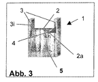
Entsprechend Abb. 3 kann erfindungsgemäß gleichfalls eine Abschneidevorrichtung mit nur einem einseitigen Schneidmesser (4) genutzt werden. In diesem Fall erfolgt der Einschnitt in den abzuschneidenden Klebebandstreifen an diesem Messer. Der Einschnitt wird an der Vorderkante (2a) der Filmauflagefläche (2) entsprechend weitergeleitet, so daß eine glatte Schnittkante über die gesamte Breite des eingesetzten Selbstklebefilmes erzeugt wird.According to Fig. 3, a cutting device can also be used according to the invention only a one-sided cutting knife (4) can be used. In this case, the incision is made in the tape strips to be cut off on this knife. The incision is forwarded accordingly at the front edge (2a) of the film support surface (2), so that a smooth cutting edge over the entire width of the self-adhesive film used is produced.
Die erfindungsgemäß nutzbaren Schneidmesser können von unterschiedlicher Form sein. Beispiele umfassen dreieckige Messergeometrien mit gerader Messerschneide. Weitere Formen beinhalten runde Messerschneiden oder auch solche, die aus mehreren geraden und // oder runden Segmenten aufgebaut sind. Um Klebefilme unterschiedlicher Breite bei gleichzeitiger Verwendung starr fixierter Messer in allen Fällen abschneiden zu können, soll der Abstand der über die Filmauflagefläche (2) hervorstehenden Schneiden voneinander kleiner als die Breite des verwendeten Klebefilmes sein.The cutting knives which can be used according to the invention can have different shapes his. Examples include triangular knife geometries with a straight knife edge. Other shapes include round knife edges or those that consist of several straight and // or round segments are constructed. To different adhesive films Cut the width in all cases while using rigidly fixed knives to be able to, the distance that protrudes beyond the film support surface (2) Cutting from each other may be smaller than the width of the adhesive film used.
Bei dreieckigen Messergeometrien mit gerader Messerschneide steigt die Verletzungsgefahr
mit wachsender Höhe der Messer an den Innenseiten der seitlichen Stege (3i)
und mit der Breite der Schneidmesser oberhalb der Filmauflagefläche an. Beträgt der
Neigungswinkel der Schneidmessers (4) in Abb. 1 45°, so kann bei einer Messerhöhe
an den Innenseiten der seitlichen Stege (3i) von < ca. 3 mm, welche in diesem Fall
gleich der Messerbreite oberhalb der Filmauflagefläche (2) ist, eine Fingerverletzung
effektiv auch dann ausgeschlossen werden, wenn der Finger kräftig in die Kante gepreßt
wird, in der sich das Messer befindet. Eine Reduzierung der Neigungswinkel der
Messerschneiden reduziert die Verletzungsgefahr bei gleichbleibender Messerbreite
oberhalb der Filmauflagefläche (2) und ermöglicht so die verletzungsfreie Verwendung
von Messern, welche eine größere Breite oberhalb der Filmauflagefläche (2) aufweisen.
Entsprechende Messer lassen sich bevorzugt einsetzen, wenn Klebefilme unterschiedlicher
Breite auf einem Dispenser verarbeitet werden sollen . So ist bei einem Neigungswinkel
der Schneidkante von 30° bis zu einer seitlichen Messerhöhe an den Innenseiten
der Stege (3i) der Abb. 1 von 2,5 mm nicht mit einer Verletzungsgefahr zu rechnen. Die
Messerbreite oberhalb der Filmauflagefläche (2) in Abb. 1 beträgt in diesem Fall jeweils
5 mm. Bei einem Neigungswinkel von 15° können Verletzungen ab einer seitlichen Messerhöhe
an den Innenseiten der seitlichen Stege (3i) von < ca. 2,0 mm weitestgehend
ausgeschlossen werden. In diesem Fall betragen die jeweilige Messerbreiten oberhalb
der Filmauflagefläche (2) in Abb. 1 ca. 7,5 mm.With triangular knife geometries with a straight knife edge, the risk of injury increases
with increasing height of the knives on the inside of the side webs (3i)
and with the width of the cutting knife above the film contact surface. Is the
Inclination angle of the cutting knife (4) in Fig. 1 45 °, so at a knife height
on the inside of the side webs (3i) of <approx. 3 mm, which in this case
is equal to the knife width above the film contact surface (2), a finger injury
can be effectively excluded even if the finger is pressed firmly into the edge
in which the knife is located. A reduction in the angle of inclination
Knife cutting reduces the risk of injury while the knife width remains the same
above the film contact surface (2) and thus enables injury-free use
of knives which have a greater width above the film contact surface (2).
Corresponding knives can preferably be used if adhesive films are different
Width to be processed on a dispenser. So is at an angle of inclination
the cutting edge from 30 ° up to a lateral knife height on the inside
the webs (3i) of Fig. 1 of 2.5 mm should not be expected to pose a risk of injury. The
Knife width above the film contact surface (2) in Fig. 1 is in this case in each
Bei konkav gegenüber der Filmauflagefläche (2) ausgeführten Messerschneiden ist eine Verletzungsgefahr auch bei großen Messerbreiten deutlich reduziert. Entsprechende Messer können daher bevorzugt eingesetzt werden, wenn die zu verarbeitenden Klebefilme in ihrer Breite sehr weit variieren. Speziell können die Messer über die gesamte Breite der Filmauflagefläche oberhalb selbiger verlaufen.If the knife edges are concave with respect to the film contact surface (2), there is one Risk of injury significantly reduced even with large knife widths. Appropriate Knives can therefore preferably be used when the adhesive films to be processed vary widely in width. Specifically, the knives can cover the entire The width of the film contact surface is above the same.
In einer speziellen Ausführung kann der Abstand der Schneidmesser voneinander über die Breite der Abschneidevorrichtung derart positionierbar ausgestaltet sein, daß eine Anpassung an Klebefilme unterschiedlicher Breite vorgenommen werden kann. Z. B. kann einer oder beide der seitlichen Stege (3) ausgerüstet mit Schneidmessern (4) in Abb. 1 parallel zur Filmauflagefläche beweglich angeordnet sein. Vorteilhafterweise können zur einfachen und präzisen Breitenpositionierung Einrastungen in die Abschneidevorrichtung integriert sein, z. B. für die marktgängigen Klebefilmbreiten 12 mm, 15 mm und 19 mm.In a special version, the distance between the cutting knives can be about the width of the cutting device can be designed so that a position Adaptation to adhesive films of different widths can be made. E.g. one or both of the side webs (3) can be equipped with cutting blades (4) in Fig. 1 can be arranged movably parallel to the film support surface. advantageously, can be snapped into the cutting device for simple and precise width positioning be integrated, e.g. B. for the standard adhesive film widths 12 mm, 15 mm and 19 mm.
Erfindungsgemäße Abschneidevorrichtungen für Selbstklebefilme können in einer großen Anzahl von Dispensertypen genutzt werden. Geeignete Dispensertypen umfassen Tisch- und Handdispenser, bei denen das die Klebebandrolle aufnehmende Gehäuse räumlich von Filmauflage und Abschneidevorrichtung getrennt vorliegt, Kompaktdispenser sowie ebenfalls Transferdispenser, wie zuvor beschrieben.Cutting devices for self-adhesive films according to the invention can be used in a large range Number of dispenser types can be used. Suitable dispenser types include Table and handheld dispensers, in which the housing holding the adhesive tape roll is spatially separated from the film support and the cutting device, compact dispenser as well as transfer dispensers as previously described.
Als Schneidmesser sind einen große Anzahl handelsüblicher Klingenmesser geeignet. Typische Beispiele umfassen Klingenmesser aus Stahl mit bevorzugten Dicken zwischen ca 0,08 mm und 0,8 mm. Stähle können einer speziellen Härtung, z. B. einer Titannitridbeschichtung unterzogen worden sein, um erhöhte Messerstandzeiten zu erlangen. Ein typischer Schleifwinkel beträgt 10°, wobei geeignete Klingenmesser sowohl einen ein- als auch beidseitigen Schliff aufweisen können. Vorgenannte Ausführungen verstehen sich beispielhaft. A large number of commercially available blade knives are suitable as cutting knives. Typical examples include steel knife blades with preferred thicknesses between approx. 0.08 mm and 0.8 mm. Steels can be hardened, e.g. B. a titanium nitride coating have undergone in order to achieve increased knife service life. A typical grinding angle is 10 °, with suitable blade knives both can have a cut on both sides. The aforementioned versions understand each other as an example.
Am Abroller werden 10 Klebefilmstreifen in einer Länge von je ca. 3 cm abgetrennt. Das Abtrennen erfolgt durch Ziehen des Klebefilmstreifens in einem Winkel von ca. 75° zur Vorderseite der Abschneidevorrichtung ohne seitliche Auslenkung der Klebefilmstreifen (Abschneiden nach vorn). Der Versuch kann ebenfalls mit seitlicher Auslenkung des Klebefilmes erfolgen (schräges Abschneiden). In letzterem Fall wird der Klebefilm jeweils von einer Seite beginnend abgeschnitten. Die erhaltenen Klebefilmstreifen werden anschließend durch leichtes Anreiben mit dem Finger luftblasenfrei auf Kunststoffplatten bestehend aus hart PVC (Typ: Kömadur WA; Lieferant: Fa. Krüger / Wedel) verklebt, danach 5 mal mit einer 1 kg schweren Andruckrolle überrollt. Die mit Klebefilmstreifen versehenen PVC-Platten werden nachfolgend 3 Tage im Klimaraum (T = 23 ± 2°C; Luftfeuchte = 50 ± 10%) gelagert.10 strips of adhesive film each with a length of approx. 3 cm are cut off on the dispenser. The The tape is removed by pulling the adhesive film at an angle of approx. 75 ° to the Front of the cutting device without lateral deflection of the adhesive film strips (Cut forward). The experiment can also be carried out with lateral deflection of the Adhesive films take place (oblique cutting). In the latter case, the adhesive film is each cut off from one side. The adhesive film strips obtained are Then, by rubbing lightly with your finger, free of air bubbles on plastic plates consisting of hard PVC (type: Kömadur WA; supplier: Krüger / Wedel), then rolled over 5 times with a 1 kg pressure roller. The one with adhesive film strips PVC sheets provided are subsequently stored in the climatic room for 3 days (T = 23 ± 2 ° C; Humidity = 50 ± 10%).
Zur Prüfung auf einreißfreies Wiederablösen werden die Klebestreifen manuell vom PVC-Haftgrund abgelöst. Hierzu werden die Klebefilmstreifen von einer Ecke beginnend mit dem Fingernagel abgelöst, danach vorsichtig bis zur Hälfte der Klebefilmstreifenlänge abgschält. An der gegenüberliegenden Trennkante werden die Klebefilmstreifen in gleicher Weise abgelöst. Insgesamt werden so an den 10 Klebefilmstreifen 20 Ablöseversuche vorgenommen. Gezählt werden die Versuche, bei denen sich die Klebefilmstreifen ohne an der abgetrennten Kante einzureißen, vom PVC ablösen lassen.To check for tear-free redetachment, the adhesive strips are removed manually from the PVC primer removed. To do this, the adhesive film strips are started from a corner detached with your fingernail, then carefully up to half the length of the adhesive film abgschält. The adhesive film strips are on the opposite separating edge replaced in the same way. In total, there are 20 on the 10 adhesive film strips Attempted replacement. The trials in which the Peel off the adhesive film strips from the PVC without tearing at the severed edge to let.
Ein tesa Tischabroller 6059, welcher mit der zu prüfenden Abschneidevorrichtung ausgerüstet ist, steht in Längsrichtung vor der Versuchsperson auf einem Tisch. Die Versuchsperson hat über die Hand einen Glovex Vinyl Handschuh (Artikel Nr.: 71259) gezogen. Sie legt den Zeigefinger auf die Auflagefläche und preßt den Finger mit ca. 5N Andruckkraft gegen die seitlich angeordnete Messerklinge. Anschließend wird der Finger des Handschuhs auf Schnittverletzungen untersucht. Der Test wird mit Versuchspersonen durchgeführt, die Fingerdurchmesser von ca. 12 ± 2 mm haben.A tesa table dispenser 6059, which is equipped with the cutting device to be tested is in the longitudinal direction in front of the test subject on a table. The subject pulled a Glovex vinyl glove (item no .: 71259) over his hand. She puts her index finger on the support surface and presses the finger with approx. 5N Pressure against the knife blade arranged on the side. Then the finger of the glove examined for cuts. The test is done with test subjects with a finger diameter of approx. 12 ± 2 mm.
Am Abroller werden 10 Klebefilmstreifen in einer Länge von je ca. 3 cm abgetrennt. Das Abtrennen erfolgt wie unter "Prüfung auf einreißfreies Wiederablösen applizierter Klebefilme" beschrieben. Abgeschnitten wird ohne seitliche Auslenkung der Klebefilmstreifen (Abschneiden nach vorn). Die zum Abtrennen der Klebefilmstreifen benötigte Kraft wird subjektiv mit derjenigen verglichen, die zum Abtrennen am tesa Tischabroller 6059 notwendig ist. Die Beurteilung lautet:
- "mäßig schwer" wenn die Abtrennkraft subjektiv derjenigen Kraft vergleichbar ist, die zum Abtrennen eines Stückes tesa Multi-Film am tesa Tischabroller 6059 nötig ist.
- "sehr leicht" wenn die Abtrennkraft subjektiv derjenigen Kraft vergleichbar ist, die zum Abtrennen eines Stückes tesa Multi-Film an einem tesa Tischabroller 6059 benötigt wird, bei welchem das vorhandene gezahnte Schneidmesser gegen ein Rasierklingenmesser ausgetauscht ist (Klingendicke = 0,3 mm; Material: Stahl; Schneide beidseitig senkrecht geschliffen; Schleifwinkel = 2 * 10°).
- "Moderately difficult" if the severing force is subjectively comparable to the force required to tear off a piece of tesa Multi-Film on the tesa table dispenser 6059.
- "very light" if the severing force is subjectively comparable to the force required to sever a piece of tesa Multi-Film on a tesa table dispenser 6059, in which the toothed cutting knife is exchanged for a razor blade knife (blade thickness = 0.3 mm; material : Steel; cutting edge vertically ground on both sides; grinding angle = 2 * 10 °).
Beim Gehäuse eines tesa Tischabrollers 6059 wird die vorhandene aufgeklebte Abschneidevorrichtung
mit Klebefilmauflage durch eine aus Aluminium bestehende Abschneidevorrichtung
ersetzt, welche in ihrem oberen Teil entsprechend Abb. 1 ausgeformt
ist. An eine parallel zur Standfläche des Klebebanddispensers verlaufende Klebefilmauflagefläche
der Abmessungen 20 mm * 3 mm (Breite * Tiefe) grenzen zu beiden
Seiten Stege der Abmessungen 5 mm * 2,5 mm * 3 mm (Höhe * Breite * Tiefe). An
der Vorderseite der Klebefilmauflage sind auf beide Eckbereiche rechtwinklige dreiekkige
Rasierklingenmesser (Dicke: 0,3 mm; beidseitig senkrecht geschliffener Stahl;
Schleifwinkel = 2 * 10°) der Abmessungen 5 mm * 5 mm (seitliche Höhe * untere Breite)
derart aufgeklebt, daß die untere Kante der Schneidmesser parallel zur Standfläche des
Klebebanddispensers verläuft und jeweils ein dreieckiges Stück der Schneidmesser der
Höhe 2 mm und der Breite 2 mm über die Filmauflagefläche heraussteht. Die Vorderkante
der Filmauflagefläche ist rechtwinklig ausgeführt.In the case of a tesa table dispenser 6059, the existing cut-off device is attached
with adhesive film overlay by an aluminum cutting device
replaced, which is shaped in its upper part according to Fig. 1
is. On an adhesive film contact surface that runs parallel to the base of the adhesive tape dispenser
the dimensions 20 mm * 3 mm (width * depth) border on both
Side bars measuring 5 mm * 2.5 mm * 3 mm (height * width * depth). On
The front of the adhesive film overlay is triangular on both corner areas
Razor blade knife (thickness: 0.3 mm; steel ground vertically on both sides;
Grinding angle = 2 * 10 °) of
Selbstklebefilme #1 bis #6 von 19 mm Breite werden vergleichend auf Abschneidbarkeit,
Struktur der Schnittkante und einreißfreies Wiederablösen verklebter Klebefilmstreifen
geprüft. Weiter wird die Verletzungsgefahr an den Schneidmessern beurteilt. Es ergeben
sich nachfolgende Eigenschaften:
In allen Fällen ergibt sich bei Verwendung der erfindungsgemäßen Abschneidevorrichtung eine glatte und gerade Schnittkante. Sämtliche Klebefilme lassen sich sowohl beim Abschneiden nach vorn als auch beim schrägem Abschneiden sehr leicht, die Kalanderfolie auf Basis eines Gemisches aus PE und EVAc-Copolymer leicht abtrennen. Nahezu alle Klebestreifen lassen sich nach dem Verkleben einreißfrei wiederablösen.In all cases, the cutting device according to the invention results a smooth and straight cut edge. All adhesive films can be used with both Cutting off to the front as well as when cutting diagonally very easily, the calender film Separate easily based on a mixture of PE and EVAc copolymer. Nearly all adhesive strips can be removed without tearing after gluing.
Zum Vergleich werden die Klebefilme #1 bis #3 auf dem mit einem Originalmesser ausgerüsteten
tesa Abroller 6059 verarbeitet. Das Abtrennen wird in allen Fällen als leicht
beim schrägem Abschneiden und als mäßig schwer beim mittigen Abschneiden beurteilt.
Ein einreißfreies Wiederablösen verklebter Klebefilmstreifen ist lediglich in ca. 10
bis 30% aller Fälle möglich.For comparison, the
Ein analog Bspl. 1 modifizierter tesa Tischabroller 6059 wird mit Schneidmessern unterschiedlicher
Form versehen. Unter "Messerform" ist in der nachfolgenden Tabelle die
Form des jeweils erprobten Messers skizziert. Unter "Messermaße" ist mit a die Messerhöhe
des Schneidmessers an der Innenkante der seitlichen Stege (3i) in Abb. 1 sowie
mit b die Breite der Schneidmesser an der Vorderkante der Filmauflagefläche (2a) in
Abb. 1 angegeben. In allen Fällen wurde ein symmetrischer Versuchsaufbau gewählt.
tesa Multi-Film (= Klebefilm #2 aus Bspl. 1) in Breiten von 12 mm, 15 mm und 19 mm
wird vergleichend auf Schneidbarkeit, Struktur der Schnittkante und einreißfreies Wiederablösen
verklebter Klebefilmstreifen geprüft. Weiter wird die Verletzungsgefahr an
den Schneidmessern beurteilt. Für Versuch 2.6 wurde ein Originalmesser des tesa
Tischabrollers 6059 auf die angegebene Form zugeschnitten. Für die übrigen Versuche
wurden Messer entsprechend Bspl. 1 als Ausgangsmaterial gewählt. Es ergeben sich
nachfolgende Eigenschaften:
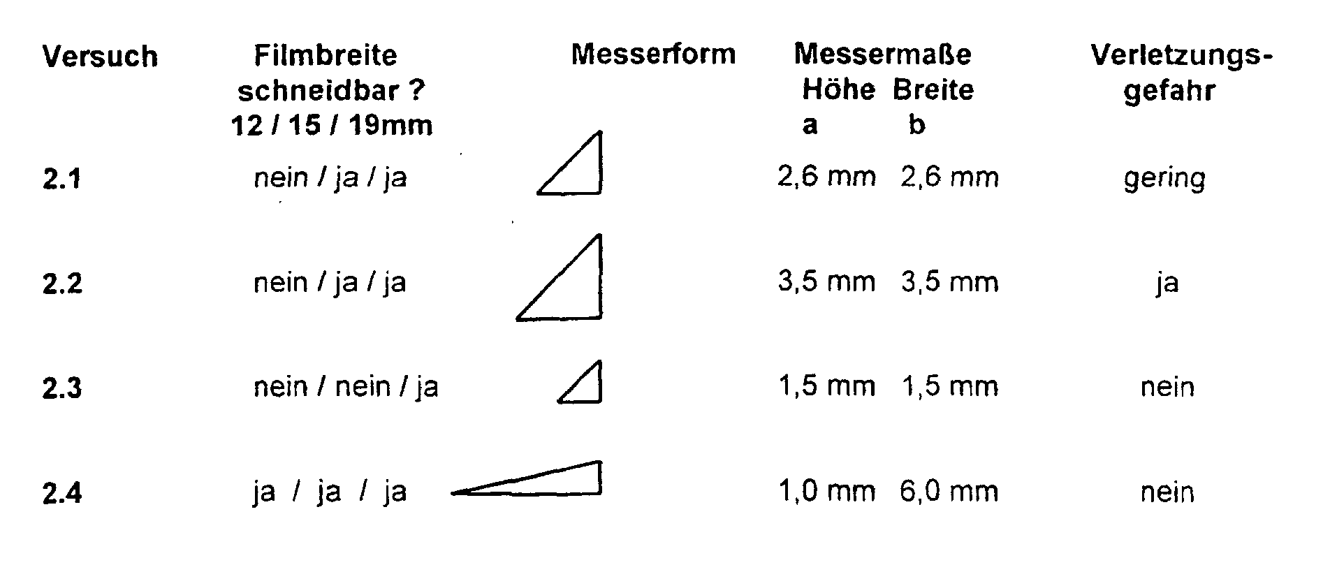
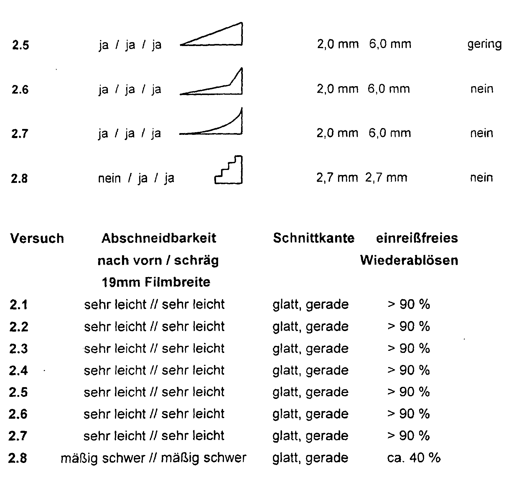
Je nach Messergeometrie und Messergröße lassen sich Versuchsaufbauten realisieren, welche ein Schneiden aller Klebefilmbreiten oder nur eines Teiles zuverlässig erlauben. Dreieckige Messergeometrien auch mit niedrigen Neigungswinkeln ermöglichen ein sehr leichtes und glattes Abschneiden aller geprüften Klebefilmbreiten bei gleichzeitig nur geringer oder keiner Verletzungsgefahr bei direktem Kontakt der Messer mit einem Finger. Besonders vorteilhaft erweisen sich Schneidmesser, welche bzgl. der Filmauflagefläche konkav ausgeformt sind. Das einreißfreie Wiederablösen der Selbstklebefilme ist durch die Verwendung von nicht gezahnten, glatten, sehr scharfen Schneidmessern im Vgl. zu einem klassischen Dispensermesser in allen Fällen deutlich verbessert.Depending on the knife geometry and knife size, test setups can be implemented, which reliably cut all adhesive film widths or only a part. Triangular knife geometries, even with low angles of inclination, allow a very easy and smooth cutting of all tested adhesive film widths at the same time only little or no risk of injury if the knives come into direct contact with a finger. Cutting knives with regard to the film contact surface have proven to be particularly advantageous are concave. The tear-free removal of the self-adhesive films is through the use of non-toothed, smooth, very sharp cutting knives in the Compared to a classic dispenser knife significantly improved in all cases.
Für sämtliche Versuchsaufbauten wird eine sehr leichte Schneidbarkeit des verwendeten Klebefilmes mit Bildung einer glatten Schnittkante beobachtet. Mit sinkendem Messerüberstand wird durch die geringe Entfernung der Schneidemesser zur Filmauflagefläche ein Minimum an Verletzungsgefahr realisiert.A very easy cutability of the used is used for all experimental setups Adhesive film observed with formation of a smooth cut edge. With falling knife overhang is due to the short distance of the cutting knife to the film contact surface realized a minimum risk of injury.
Claims (11)
- Adhesive tape dispenser with a cutting-off device, having a blade, where the cutting-off device (1) has a resting surface (2) for the adhesive tape (22) to be cut off, with two lateral webs (3) for the lateral guidance of the adhesive tape (22) on both the edges of the said resting surface, a cutting blade (4) being arranged on the inner side of one or both webs (3) in such a way that the blade edge is inclined at an angle obliquely with respect to the resting surface (2), the webs (3) being made higher or the same height as the cutting blade or blades (4), characterized in that the cutting blades (4) are arranged in the region of the lateral webs (3), and are shielded by them, in such a way that they cannot be reached with a finger in such a way that fingers are injured, the lateral webs (3) being formed in such a way that they do not protrude beyond the cutting blades (4) and the front edge (2a) of the resting surface (2) being arranged in such a way that it continues the cuts made by the cutting blades (4) in the adhesive tape (22) in such a directed manner that a smooth cut edge is produced in the adhesive tape (22).
- Adhesive tape dispenser according to Claim 1, characterized in that the cutting blades (4) are arranged on the front side, i.e. the side on which a hanging-down piece of adhesive tape (22) is removed, of the cutting-off device (5).
- Adhesive tape dispensed according to Claim 1, charecterized in that the surfaces of the cutting blades (4) are arranged parallel to the front side of the cutting-off device (5).
- Adhesive tape dispensed according to Claim 1, characterized in that there is a cutting blade (4) arranged on each of the both the webs (3).
- Adhesive tape dispenser according to Claim 1, characterized in that the angle by which the blades (4) are inclined with respect to the resting surface (2) is 85° to 2°, in particular 70° to 5°, preferably 50° to 5°.
- Adhesive tape dispenser according to Claim 1, characterized in that the front side of the cutting-off device (5) is formed with a straight edge (2a), with which the edges of the cutting blades (4) are aligned in one line.
- Adhesive tape dispenser according to Claim 1, characterized in that the cutting blades (4) take the form of separate blades or a one-part blade.
- Adhesive tape dispenser according to Claim 1, characterized in that the cutting blades (4) are designed in a triangular form and are respectively arranged on the lateral webs (3).
- Adhesive tape dispenser according to Claim 1, characterized in that the cutting blades (4) are designed in a concave form with respect to the film resting surface (2) and are respectively arranged on the lateral webs (3).
- Adhesive tape dispenser according to Claim 1, characterized in that the distance apart of the cutting blades (4) is made such that it can be set in position.
- Use of an adhesive tape dispenser according to one of Claims 1 - 10 for cutting off adhesive tapes without injury with a backing consisting of biaxially oriented or highly stretched film, in particular of polyolefin.
Applications Claiming Priority (2)
| Application Number | Priority Date | Filing Date | Title |
|---|---|---|---|
| DE19741618A DE19741618A1 (en) | 1997-09-20 | 1997-09-20 | Adhesive tape dispenser and its use |
| DE19741618 | 1997-09-20 |
Publications (3)
| Publication Number | Publication Date |
|---|---|
| EP0903312A2 EP0903312A2 (en) | 1999-03-24 |
| EP0903312A3 EP0903312A3 (en) | 1999-04-28 |
| EP0903312B1 true EP0903312B1 (en) | 2004-04-14 |
Family
ID=7843113
Family Applications (1)
| Application Number | Title | Priority Date | Filing Date |
|---|---|---|---|
| EP98117041A Expired - Lifetime EP0903312B1 (en) | 1997-09-20 | 1998-09-09 | Adhesive tape dispenser and use thereof |
Country Status (4)
| Country | Link |
|---|---|
| US (1) | US6553884B1 (en) |
| EP (1) | EP0903312B1 (en) |
| DE (2) | DE19741618A1 (en) |
| ES (1) | ES2217472T3 (en) |
Families Citing this family (6)
| Publication number | Priority date | Publication date | Assignee | Title |
|---|---|---|---|---|
| US20060169732A1 (en) * | 2003-01-23 | 2006-08-03 | Frits Ludvigsen | Device for dispensing two-sided adhesive pieces of an adhesive |
| US8596031B2 (en) * | 2005-05-20 | 2013-12-03 | San Jamar, Inc. | Wrap dispensing station and method |
| US9975724B2 (en) * | 2011-08-25 | 2018-05-22 | Lamus Enterprises Inc. | Tape applicator |
| USD820447S1 (en) | 2015-03-23 | 2018-06-12 | Sparo, Inc. | Spirometer device |
| US12005651B2 (en) | 2020-11-20 | 2024-06-11 | Intertape Polymer Corp. | Tape applicator with split wiper |
| CN117140943B (en) * | 2023-10-30 | 2024-02-13 | 山东普克汽车饰件有限公司 | Automotive interior spare tectorial membrane cutting device |
Family Cites Families (18)
| Publication number | Priority date | Publication date | Assignee | Title |
|---|---|---|---|---|
| US2540697A (en) * | 1948-08-06 | 1951-02-06 | George E Staples | Tape dispenser |
| GB765497A (en) * | 1953-11-10 | 1957-01-09 | Johnson & Johnson | Cutting device |
| GB765496A (en) | 1953-11-19 | 1957-01-09 | Baldwin Lima Hamilton Corp | Billet container for metal extrusion presses |
| US2992582A (en) * | 1958-03-31 | 1961-07-18 | Johnson & Johnson | Pressure-sensitive tape dispenser |
| DE1083153B (en) * | 1958-09-17 | 1960-06-09 | Claus Koenig G M B H | Adhesive tape dispenser with feed table and straight cutting device |
| DE1085440B (en) * | 1959-10-23 | 1960-07-14 | Claus Koenig G M B H | Adhesive tape dispenser with feed table and straight cutting device |
| US3050853A (en) * | 1960-09-26 | 1962-08-28 | Crane Packing Co | Tape dispenser |
| US3470781A (en) * | 1967-04-21 | 1969-10-07 | Crane Packing Co | Positive feed device for tape dispenser |
| US3508692A (en) * | 1968-06-10 | 1970-04-28 | Victor E Holtan | Tape dispenser and cutter |
| US3635473A (en) * | 1968-10-10 | 1972-01-18 | Sekisui Adoheya Kogya Kk | Tape cutter |
| CH532525A (en) * | 1970-12-17 | 1973-01-15 | Hansjoerg Dipl Ch Rothenberger | Device for applying a self-adhesive tape |
| US4196647A (en) * | 1978-08-15 | 1980-04-08 | Reynolds Metals Company | Carton for dispensing and cutting sheet material |
| US4244254A (en) * | 1979-08-17 | 1981-01-13 | Reynolds Metals Company | Carton for cutting and dispensing sheet material |
| US4608894A (en) * | 1983-02-09 | 1986-09-02 | Lee Ki S | Adhesive tape-cutting device |
| DE8904789U1 (en) * | 1989-04-17 | 1989-08-10 | Steuer, Herbert, 6380 Bad Homburg | Cutting device for tapes on unwinders |
| FR2656601B1 (en) * | 1989-12-28 | 1992-04-24 | Maurice Granger | APPARATUS FOR SIMULTANEOUSLY DISPENSING AND CUTTING TAPES OF ROLLED MATERIALS. |
| US5146828A (en) * | 1991-03-29 | 1992-09-15 | Huang Hong Yuan | Wrap film cutter |
| US5678689A (en) * | 1995-08-22 | 1997-10-21 | Clark; Mary J. | Two side taping apparatus |
-
1997
- 1997-09-20 DE DE19741618A patent/DE19741618A1/en not_active Ceased
-
1998
- 1998-09-09 ES ES98117041T patent/ES2217472T3/en not_active Expired - Lifetime
- 1998-09-09 EP EP98117041A patent/EP0903312B1/en not_active Expired - Lifetime
- 1998-09-09 DE DE59811180T patent/DE59811180D1/en not_active Expired - Lifetime
- 1998-09-16 US US09/154,123 patent/US6553884B1/en not_active Expired - Fee Related
Also Published As
| Publication number | Publication date |
|---|---|
| DE19741618A1 (en) | 1999-04-01 |
| ES2217472T3 (en) | 2004-11-01 |
| US6553884B1 (en) | 2003-04-29 |
| DE59811180D1 (en) | 2004-05-19 |
| EP0903312A3 (en) | 1999-04-28 |
| EP0903312A2 (en) | 1999-03-24 |
Similar Documents
| Publication | Publication Date | Title |
|---|---|---|
| DE69721973T2 (en) | CUTTER | |
| EP0640236B1 (en) | Sheet of labels, method and device for its production | |
| EP0696628A2 (en) | Adhesive tape | |
| DE69915707T2 (en) | SAFETY KNIFE CUTTING UNIT | |
| DE69805636T2 (en) | CUTTING KNIFE TO RIP LEAF MATERIALS | |
| DE1594179C3 (en) | Hand-tearable self-adhesive tape and process for its manufacture | |
| DE4318277C1 (en) | Use of notch cutters | |
| EP0903312B1 (en) | Adhesive tape dispenser and use thereof | |
| EP2766287B1 (en) | Dispenser | |
| EP0233281B1 (en) | Dispenser with cutting device | |
| DE102009033575A1 (en) | Foil knife with suction chamber | |
| EP0332072A2 (en) | Package for objects, particularly parallelepiped-shaped | |
| WO2009030491A1 (en) | Device and method for guiding a material web | |
| GB2389356A (en) | A disposable package and cutting apparatus | |
| DE102011079544A1 (en) | Unwinder for unwinding single-side sticking adhesive band from roller to cover metal sheet rebate in automobile engineering during e.g. welding sheet metal parts, has retaining roller set in rotation by belt during movement of adhesive band | |
| DE19641094C1 (en) | Stamping self-adhesive labels from plastic strip | |
| EP0943545B1 (en) | Cutting blade for an adhesive tape dispenser | |
| DE29821829U1 (en) | Adhesive tape dispenser and its use | |
| DE202018102992U1 (en) | Recording unit for cling film | |
| EP0714845B1 (en) | Portable device for the cross-cutting to length of adhesive tapes | |
| DE10355901B4 (en) | Refillable dispenser for paper and / or film rolls | |
| EP4313596B1 (en) | Method for producing an adhesive composite film | |
| JP3246869B2 (en) | Sheet-shaped uncured compound punching method and punching jig used in the method | |
| EP1792863B1 (en) | Severing device for webs | |
| DE8015755U1 (en) | DISPENSER HOUSING FOR A TAPE ROLL |
Legal Events
| Date | Code | Title | Description |
|---|---|---|---|
| PUAI | Public reference made under article 153(3) epc to a published international application that has entered the european phase |
Free format text: ORIGINAL CODE: 0009012 |
|
| PUAL | Search report despatched |
Free format text: ORIGINAL CODE: 0009013 |
|
| AK | Designated contracting states |
Kind code of ref document: A2 Designated state(s): DE ES FR GB IT |
|
| AX | Request for extension of the european patent |
Free format text: AL;LT;LV;MK;RO;SI |
|
| AK | Designated contracting states |
Kind code of ref document: A3 Designated state(s): AT BE CH CY DE DK ES FI FR GB GR IE IT LI LU MC NL PT SE |
|
| AX | Request for extension of the european patent |
Free format text: AL;LT;LV;MK;RO;SI |
|
| 17P | Request for examination filed |
Effective date: 19990401 |
|
| AKX | Designation fees paid |
Free format text: DE ES FR GB IT |
|
| RAP1 | Party data changed (applicant data changed or rights of an application transferred) |
Owner name: TESA AG |
|
| 17Q | First examination report despatched |
Effective date: 20020207 |
|
| GRAP | Despatch of communication of intention to grant a patent |
Free format text: ORIGINAL CODE: EPIDOSNIGR1 |
|
| RIN1 | Information on inventor provided before grant (corrected) |
Inventor name: KUBASCH, PETER Inventor name: NEUMANN, UWE Inventor name: LINDE, HANSJUERGEN, PROF. DR. Inventor name: HAZES, HANS Inventor name: REHKLAU ANDREAS Inventor name: LEIBER, JOERN, DR. Inventor name: SCHLIEPHACKE, RALF Inventor name: LUEHMANN, BERND, DR. |
|
| GRAS | Grant fee paid |
Free format text: ORIGINAL CODE: EPIDOSNIGR3 |
|
| GRAA | (expected) grant |
Free format text: ORIGINAL CODE: 0009210 |
|
| AK | Designated contracting states |
Kind code of ref document: B1 Designated state(s): DE ES FR GB IT |
|
| REG | Reference to a national code |
Ref country code: GB Ref legal event code: FG4D Free format text: NOT ENGLISH |
|
| REF | Corresponds to: |
Ref document number: 59811180 Country of ref document: DE Date of ref document: 20040519 Kind code of ref document: P |
|
| GBT | Gb: translation of ep patent filed (gb section 77(6)(a)/1977) |
Effective date: 20040602 |
|
| RAP2 | Party data changed (patent owner data changed or rights of a patent transferred) |
Owner name: TESA AG |
|
| REG | Reference to a national code |
Ref country code: ES Ref legal event code: FG2A Ref document number: 2217472 Country of ref document: ES Kind code of ref document: T3 |
|
| ET | Fr: translation filed | ||
| PLBE | No opposition filed within time limit |
Free format text: ORIGINAL CODE: 0009261 |
|
| STAA | Information on the status of an ep patent application or granted ep patent |
Free format text: STATUS: NO OPPOSITION FILED WITHIN TIME LIMIT |
|
| 26N | No opposition filed |
Effective date: 20050117 |
|
| PGFP | Annual fee paid to national office [announced via postgrant information from national office to epo] |
Ref country code: ES Payment date: 20090922 Year of fee payment: 12 |
|
| PGFP | Annual fee paid to national office [announced via postgrant information from national office to epo] |
Ref country code: GB Payment date: 20090922 Year of fee payment: 12 |
|
| REG | Reference to a national code |
Ref country code: FR Ref legal event code: CJ Ref country code: FR Ref legal event code: CD |
|
| PGFP | Annual fee paid to national office [announced via postgrant information from national office to epo] |
Ref country code: IT Payment date: 20090925 Year of fee payment: 12 |
|
| GBPC | Gb: european patent ceased through non-payment of renewal fee |
Effective date: 20100909 |
|
| PG25 | Lapsed in a contracting state [announced via postgrant information from national office to epo] |
Ref country code: IT Free format text: LAPSE BECAUSE OF NON-PAYMENT OF DUE FEES Effective date: 20100909 |
|
| PG25 | Lapsed in a contracting state [announced via postgrant information from national office to epo] |
Ref country code: GB Free format text: LAPSE BECAUSE OF NON-PAYMENT OF DUE FEES Effective date: 20100909 |
|
| REG | Reference to a national code |
Ref country code: ES Ref legal event code: FD2A Effective date: 20111019 |
|
| PG25 | Lapsed in a contracting state [announced via postgrant information from national office to epo] |
Ref country code: ES Free format text: LAPSE BECAUSE OF NON-PAYMENT OF DUE FEES Effective date: 20100910 |
|
| PGFP | Annual fee paid to national office [announced via postgrant information from national office to epo] |
Ref country code: DE Payment date: 20130930 Year of fee payment: 16 |
|
| PGFP | Annual fee paid to national office [announced via postgrant information from national office to epo] |
Ref country code: FR Payment date: 20130919 Year of fee payment: 16 |
|
| REG | Reference to a national code |
Ref country code: DE Ref legal event code: R119 Ref document number: 59811180 Country of ref document: DE |
|
| REG | Reference to a national code |
Ref country code: DE Ref legal event code: R119 Ref document number: 59811180 Country of ref document: DE Effective date: 20150401 |
|
| REG | Reference to a national code |
Ref country code: FR Ref legal event code: ST Effective date: 20150529 |
|
| PG25 | Lapsed in a contracting state [announced via postgrant information from national office to epo] |
Ref country code: DE Free format text: LAPSE BECAUSE OF NON-PAYMENT OF DUE FEES Effective date: 20150401 |
|
| PG25 | Lapsed in a contracting state [announced via postgrant information from national office to epo] |
Ref country code: FR Free format text: LAPSE BECAUSE OF NON-PAYMENT OF DUE FEES Effective date: 20140930 |