EP0902735B1 - Machine a coulee continue - Google Patents
Machine a coulee continue Download PDFInfo
- Publication number
- EP0902735B1 EP0902735B1 EP97920447A EP97920447A EP0902735B1 EP 0902735 B1 EP0902735 B1 EP 0902735B1 EP 97920447 A EP97920447 A EP 97920447A EP 97920447 A EP97920447 A EP 97920447A EP 0902735 B1 EP0902735 B1 EP 0902735B1
- Authority
- EP
- European Patent Office
- Prior art keywords
- strand
- mold
- mould
- continuous casting
- strand guide
- Prior art date
- Legal status (The legal status is an assumption and is not a legal conclusion. Google has not performed a legal analysis and makes no representation as to the accuracy of the status listed.)
- Expired - Lifetime
Links
- 238000009749 continuous casting Methods 0.000 title claims description 14
- 238000009434 installation Methods 0.000 claims description 11
- 238000005452 bending Methods 0.000 claims description 5
- 229910017052 cobalt Inorganic materials 0.000 claims description 3
- 239000010941 cobalt Substances 0.000 claims description 3
- GUTLYIVDDKVIGB-UHFFFAOYSA-N cobalt atom Chemical compound [Co] GUTLYIVDDKVIGB-UHFFFAOYSA-N 0.000 claims description 3
- 230000015572 biosynthetic process Effects 0.000 abstract description 2
- 238000005266 casting Methods 0.000 description 5
- 235000004443 Ricinus communis Nutrition 0.000 description 3
- RYGMFSIKBFXOCR-UHFFFAOYSA-N Copper Chemical compound [Cu] RYGMFSIKBFXOCR-UHFFFAOYSA-N 0.000 description 2
- 229910052802 copper Inorganic materials 0.000 description 2
- 239000010949 copper Substances 0.000 description 2
- 239000007788 liquid Substances 0.000 description 2
- 238000010276 construction Methods 0.000 description 1
- 239000002826 coolant Substances 0.000 description 1
- 238000001816 cooling Methods 0.000 description 1
- 238000012423 maintenance Methods 0.000 description 1
- 230000010355 oscillation Effects 0.000 description 1
- 230000001737 promoting effect Effects 0.000 description 1
Images

Classifications
-
- B—PERFORMING OPERATIONS; TRANSPORTING
- B22—CASTING; POWDER METALLURGY
- B22D—CASTING OF METALS; CASTING OF OTHER SUBSTANCES BY THE SAME PROCESSES OR DEVICES
- B22D11/00—Continuous casting of metals, i.e. casting in indefinite lengths
- B22D11/12—Accessories for subsequent treating or working cast stock in situ
- B22D11/128—Accessories for subsequent treating or working cast stock in situ for removing
- B22D11/1282—Vertical casting and curving the cast stock to the horizontal
-
- B—PERFORMING OPERATIONS; TRANSPORTING
- B22—CASTING; POWDER METALLURGY
- B22D—CASTING OF METALS; CASTING OF OTHER SUBSTANCES BY THE SAME PROCESSES OR DEVICES
- B22D11/00—Continuous casting of metals, i.e. casting in indefinite lengths
- B22D11/14—Plants for continuous casting
- B22D11/142—Plants for continuous casting for curved casting
Definitions
- the invention relates to a continuous caster, in particular a billet or bloom caster, with one in a frame-shaped lifting table insertable mold and a strand guiding device connected to the mold, consisting of several strand guide segments carrying strand guide rollers is formed and with a supporting the lifting table and moving mold oscillating device.
- a continuous caster of this type is already known from DE-A 19 57 689 known, in which the mold, the lifting table supporting the mold, the Mold oscillating device and a first strand guide segment within a detachable spatial frame is arranged. This frame is with everything its internals can be lifted off and replaced. At the same time, too the next strand guide segment arranged below is accessible and also interchangeable.
- a continuous caster is known in which a mold and that castor frame attached to the mold on the output side, as well as a castor frame Subsequent bending zone by a support frame which grips the mold and the bending zone can be removed from the continuous caster.
- This conception requires a multiple adjustment of the individual components to each other.
- the wall of the Mold cavity for generating the subsequent casters, as well as these Casters to the strand guide rollers of the downstream bending zone with one appropriate ruler can be set.
- the adjustment other components arranged in the mold area such as. B. the mold stirrer or Casting level measuring device could be installed.
- the object of the invention is therefore to avoid the above disadvantages and from the known Components usually used in a continuous caster, mold, lifting table, Kokillenoszillier coupled, the downstream strand guide and any additional devices, such as mold stirrers and G foolspiegelmeß coupled to form a unit in the short change times by the Formation of a format-related machine block and a reduced maintenance effort is possible due to the modular structure of the machine components.
- a first strand guide segment in one subordinate second strand guide segment is releasably integrated that a mold stirrer is supported on the second strand guide segment and that the second The strand guide segment in the area of the mold supports which supports Support for the mold or the lifting table supporting the mold and connecting elements for the joint expansion of the mold, mold stirrer and the second Have strand guide segment.
- a particular advantage of this arrangement is that that only for the first and second strand guide segment forming a structural unit Adjustment in the workshop is necessary.
- the first strand guide segment is as Castor frame and the second strand guide segment designed as a bending zone.
- the Fasteners are formed by hooks or eyes.
- a Casting level measuring device consisting of a radiator element and a Scintillation counter on the mold stirrer or on the supports of the second Strand guide segment is arranged.
- A is preferred as the radiating element Cobalt heater used.
- a particularly stable and offset-free continuous casting plant can be achieved in that the mold oscillation device as a four-eccentric oscillator with spring band guide is trained.
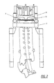
- FIG. 1 shows a schematic longitudinal section through the continuous casting plant in the area of Mold and the subsequent strand guide device shows.
- Fig. 2 illustrates the same embodiment with a modified cut.
- the continuous casting plant is supported on a fixed plant structure 1.
- the Kokillenoszillier listening 3 is fixed by a four eccentric oscillator 4 and a spring band guide 5 is formed.
- the Mold oscillating device 3 is shown and described in detail in AT-PS 384 970. It consists essentially of four arranged in the corner regions of the support frame 2 Eccentrics, which are driven by a common rotary drive, whereby the rotation thus generated by short connecting rods in a vertical Oscillating movement is implemented.
- the connecting rods of the mold oscillating device 3 are connected to a frame-shaped lifting table 6, which Picks up oscillating movement and transfers it to the mold 8. As from Fig.
- the mold 8 consists of the mold element 10 and a portal-like one Mold frame 11, in which the mold element 10 is inserted.
- the Mold element 10 has the format of the strand to be cast corresponding mold cavity on that of a copper tube or out Copper plates are formed and a back support structure with the appropriate equipment for mold cooling.
- the hot strand closes the mold 8 in the strand conveying direction promoting and supporting strand guide device 9 with a first Strand guide segment 12 and a second strand guide segment 13.
- the first strand guide segment 12 is constructed as a frame construction in which several rows of strand guide rollers forming a closed cage 14 are rotatably mounted and is detachable as a structural unit in the second strand guide segment 13 fixed.
- the second strand guide segment 13 is as two-part frame executed, the outer arch frame 15 and the Inner arch frame 16 is equipped with strand guide rollers 14 and Inner arch frame 16 is clamped to the outer arch frame 15.
- the second Strand guide segment 13 is over the outer arch frame 15 with the Fixed bearing 17 and the floating bearing 18 supported on the system structure 1.
- the Outer arch frame 15 with its strand guide rollers 14 also provides the Reference page for setting the continuous caster.
- the second strand guide segment 13 has a bearing surface 19 which the mold stirrer 20 rests and in its position at a distance from Mold element 10 is positioned.
- the second strand guide segment 13 carries 8 hoisted supports 21 with supports 22 in the area of the mold when expanding the second strand guide segment 13 with the mold 8 or the mold frame 11 engage and the simple out and Installation of the common, referred to as format-related machine block Component made of mold 8, mold stirrer 20, first strand guide segment 12 and enable the second strand guide segment 13 with a short changeover time.
- the Pads 22 with the lifting table 6 when installing or removing the machine block in Intervention can be brought.
- the raised supports 21 are also included Connecting elements 27, which are designed as hooks or eyes, provided on which a hoist can be linked for installation and removal.
- a non-oscillating Casting level measuring device 24 consisting of a radiator element 25 and a scintillation counter 26 is arranged on the mold stirrer 20.
- the radiator element 25 and Scintillation counter 26 to be attached to the raised supports 21.
- the coolant circuit for the mold is carried out by means not shown and derivatives that are led through the mold frame 11 and the lifting table 6 and automatically when the mold 8 is placed on the lifting table 6 getting closed.
Landscapes
- Engineering & Computer Science (AREA)
- Mechanical Engineering (AREA)
- Continuous Casting (AREA)
- Engine Equipment That Uses Special Cycles (AREA)
Claims (8)
- Installation de coulée continue, avec une lingotière (8), pouvant être insérée dans une table de levage (6) en forme de cadre, et un dispositif de guidage de barre ou ligne (9) se raccordant à la lingotière, constitué d'une pluralité de segments de guidage de barre (12, 13) portant des rouleaux de guidage de barre (14) et avec un dispositif d'oscillation de lingotière (3), soutenant et déplaçant la table de levage (6), caractérisée en ce qu'un premier segment de guidage de barre (12) est intégré de façon désolidarisable dans un deuxième segment de guidage de barre (13) disposé en aval, en ce qu'un agitateur de lingotière (20) est soutenu sur le deuxième segment de guidage de barre (13), et en ce que le deuxième segment de guidage de barre (13) porte, dans la zone de la lingotière (8), des appuis (21) orientés vers le haut, ces appuis (21) présentant des reposoirs (22), pour la lingotière (8) ou bien la table de levage (6) portant la lingotière (8), et des éléments de liaison (27) pour le montage et le démontage conjoint de la lingotière (8), de l'agitateur à lingotière (20) et du deuxième segment de guidage de barre (13).
- Installation de coulée continue selon la revendication 1, caractérisée en ce que le premier segment de guidage de barre (12) est réalisé sous la forme de bâti sur roulettes.
- Installation de coulée continue selon la revendication 1, caractérisée en ce que le deuxième segment de guidage de barre (13) est réalisé sous la forme de zone de flexion.
- Installation de coulée continue selon la revendication 1, caractérisée en ce que les éléments de liaison (27) sont constitués par des crochets et des oeillets.
- Installations de coulée continue selon l'une des revendications précédentes, caractérisées en ce qu'un dispositif de mesure de niveau de coulée (24), constitué d'un élément émetteur de rayonnement (25) et d'un compteur à scintillation (26), est disposé sur l'agitateur de lingotière (20) ou sur les appuis (21) du deuxième segment de guidage de barre (13).
- Installation de coulée continue selon la revendication 5, caractérisée en ce que l'élément émetteur de rayonnement (25) est constitué par un émetteur de rayonnement au cobalt.
- Installation de coulée continue selon l'une des revendications précédentes, caractérisée en ce que le dispositif d'oscillation de lingotière (3) est réalisé sous la forme d'un oscillateur à excentrique quadruple (4), équipé d'un guidage à bande élastique (5).
- Installation de coulée continue selon la revendication 1, caractérisée en ce qu'il s'agit d'une installation de coulée continue pour billettes ou pour blooms.
Applications Claiming Priority (4)
| Application Number | Priority Date | Filing Date | Title |
|---|---|---|---|
| AT88696 | 1996-05-20 | ||
| AT886/96 | 1996-05-20 | ||
| AT0088696A AT404808B (de) | 1996-05-20 | 1996-05-20 | Stranggiessanlage |
| PCT/AT1997/000092 WO1997044150A1 (fr) | 1996-05-20 | 1997-05-09 | Machine a coulee continue |
Publications (2)
| Publication Number | Publication Date |
|---|---|
| EP0902735A1 EP0902735A1 (fr) | 1999-03-24 |
| EP0902735B1 true EP0902735B1 (fr) | 2000-09-06 |
Family
ID=3502094
Family Applications (1)
| Application Number | Title | Priority Date | Filing Date |
|---|---|---|---|
| EP97920447A Expired - Lifetime EP0902735B1 (fr) | 1996-05-20 | 1997-05-09 | Machine a coulee continue |
Country Status (7)
| Country | Link |
|---|---|
| US (1) | US6145575A (fr) |
| EP (1) | EP0902735B1 (fr) |
| KR (1) | KR20000011144A (fr) |
| CN (1) | CN1080152C (fr) |
| AT (2) | AT404808B (fr) |
| DE (1) | DE59702320D1 (fr) |
| WO (1) | WO1997044150A1 (fr) |
Families Citing this family (11)
| Publication number | Priority date | Publication date | Assignee | Title |
|---|---|---|---|---|
| AT408625B (de) * | 1999-06-08 | 2002-01-25 | Voest Alpine Ind Anlagen | Stranggiessanlage |
| DE10106252A1 (de) * | 2001-02-10 | 2002-08-14 | Sms Demag Ag | Strangführung einer Stranggiessanlage sowie Anstellverfahren für deren Rollensegmente |
| AT506836B1 (de) * | 2008-05-23 | 2011-08-15 | Siemens Vai Metals Tech Gmbh | Stranggiessanlage zum giessen eines metallstranges mit knüppel- oder vorblockquerschnitt |
| DE102010054398A1 (de) * | 2010-12-08 | 2012-06-14 | Sms Siemag Ag | Stranggießanlage |
| DE102010062863A1 (de) * | 2010-12-10 | 2012-06-21 | Sms Siemag Ag | Stranggießanlage zum Gießen eines Metallstranges |
| EP2524746A1 (fr) * | 2011-05-16 | 2012-11-21 | Siemens VAI Metals Technologies GmbH | Dispositif d'oscillation pour l'oscillation d'une lingotière de coulée continu |
| CN105290349A (zh) * | 2015-10-29 | 2016-02-03 | 燕山大学 | 连铸结晶器摆动型双侧非正弦驱动装置 |
| CN105414502B (zh) * | 2015-12-07 | 2017-08-22 | 马鞍山钢铁股份有限公司 | 板坯连铸扇形段定位锁紧装置及装配方法 |
| DE102016205093A1 (de) * | 2016-03-29 | 2017-10-05 | Sms Group Gmbh | Stranggießanlage |
| DE102017220616A1 (de) | 2017-11-17 | 2019-05-23 | Sms Group Gmbh | Dünnbrammengießanlage mit wechselbarem Maschinenkopf |
| CN114309516B (zh) * | 2021-12-29 | 2023-12-05 | 深圳市以凡泰科技有限公司 | 镍钛合金高效高通量连铸装置及方法 |
Family Cites Families (14)
| Publication number | Priority date | Publication date | Assignee | Title |
|---|---|---|---|---|
| DE347057C (de) * | 1922-02-08 | Josef V Vass | Verfahren zur Herstellung von Leichtbeton und poroesen Koerpern aus Beton, Ton u. dgl. | |
| DE1508963A1 (de) * | 1966-05-28 | 1969-11-06 | Schloemann Ag | Stranggiessanlage |
| DE1957689A1 (de) * | 1969-11-17 | 1971-05-27 | Demag Ag | Stranggiessanlage fuer Metalle,insbesondere fuer Stahl |
| FR2121389B1 (fr) * | 1971-01-08 | 1973-12-07 | Fives Lille Cail | |
| US3700073A (en) * | 1971-05-13 | 1972-10-24 | United States Steel Corp | Self-aligning and flexing guide-roll rack |
| AT347057B (de) * | 1976-07-08 | 1978-12-11 | Voest Ag | Stranggiessanlage |
| DE2910547A1 (de) * | 1979-03-17 | 1980-09-25 | Schloemann Siemag Ag | Stranggiessanlage mit bogenfoermiger strangfuehrung |
| DE3000117A1 (de) * | 1980-01-03 | 1981-07-09 | Sack GmbH, 4000 Düsseldorf | Antriebs- und fuehrungsvorrichtung fuer eine stranggiesskokille |
| AT370018B (de) * | 1981-04-30 | 1983-02-25 | Voest Alpine Ag | Einrichtung zum fluchtenden einstellen zweier in strangdurchlaufrichtung benachbarter strangfuehrungsabschnitte einer stranggiessanlage |
| AT372025B (de) * | 1982-01-12 | 1983-08-25 | Voest Alpine Ag | Stranggiessanlage |
| JPS60136845U (ja) * | 1984-02-16 | 1985-09-11 | 株式会社神戸製鋼所 | 連続鋳造機の電磁撹拌用鋳型 |
| AT384970B (de) * | 1986-06-10 | 1988-02-10 | Voest Alpine Ag | Fuehrungseinrichtung fuer eine auf einem hubtisch gelagerte kokille einer stranggiessanlage |
| AT394326B (de) * | 1989-12-04 | 1992-03-10 | Voest Alpine Ind Anlagen | Stranggiesskokille |
| IT1248137B (it) * | 1991-03-05 | 1995-01-05 | Danieli Off Mecc | Lingottiera con funzioni multiple |
-
1996
- 1996-05-20 AT AT0088696A patent/AT404808B/de not_active IP Right Cessation
-
1997
- 1997-05-09 EP EP97920447A patent/EP0902735B1/fr not_active Expired - Lifetime
- 1997-05-09 AT AT97920447T patent/ATE196107T1/de not_active IP Right Cessation
- 1997-05-09 DE DE59702320T patent/DE59702320D1/de not_active Expired - Lifetime
- 1997-05-09 KR KR1019980709304A patent/KR20000011144A/ko not_active Withdrawn
- 1997-05-09 WO PCT/AT1997/000092 patent/WO1997044150A1/fr not_active Ceased
- 1997-05-09 CN CN97194416A patent/CN1080152C/zh not_active Expired - Fee Related
- 1997-05-09 US US09/194,061 patent/US6145575A/en not_active Expired - Lifetime
Also Published As
| Publication number | Publication date |
|---|---|
| KR20000011144A (ko) | 2000-02-25 |
| CN1080152C (zh) | 2002-03-06 |
| EP0902735A1 (fr) | 1999-03-24 |
| AT404808B (de) | 1999-03-25 |
| CN1217674A (zh) | 1999-05-26 |
| ATA88696A (de) | 1998-07-15 |
| WO1997044150A1 (fr) | 1997-11-27 |
| DE59702320D1 (de) | 2000-10-12 |
| US6145575A (en) | 2000-11-14 |
| ATE196107T1 (de) | 2000-09-15 |
Similar Documents
| Publication | Publication Date | Title |
|---|---|---|
| EP0902735B1 (fr) | Machine a coulee continue | |
| EP2276594B1 (fr) | Installation de coulée continue pour la coulée d'une barre métallique présentant une section transversale de billette ou de blooms | |
| DE3230573A1 (de) | Vorrichtung zum kontinuierlichen giessen von stahl | |
| DE3443258C2 (fr) | ||
| DE4444941C2 (de) | Stranggießkokille | |
| EP1365874B1 (fr) | Procede et dispositif de fabrication de brames minces | |
| EP0172449A2 (fr) | Dispositif de guidage aux bandes de coulée d'une lingotière de coulée continue à double bande | |
| EP0036611B1 (fr) | Procédé et dispositif pour soutenir une barre d'acier fabriquée par un procédé de coulée continue | |
| DE1957690A1 (de) | Vorrichtung zum Ein- oder Ausbau von Stuetzrahmen fuer Metall-,insbesondere Stahlstraenge in Stranggiessanlagen | |
| DE102017221095A1 (de) | Raupengießmaschine und Verfahren zum Herstellen eines Gießguts aus flüssigem Metall | |
| EP0010728B1 (fr) | Installation de coulée continue avec une lingotière oscillante | |
| EP0062796B1 (fr) | Installation pour le transport de feuilles de verre à l'état chaud et/ou feuilles de verre à chauffer | |
| DE2850397C2 (de) | Richtmaschine für Profilstahl | |
| EP0028339A1 (fr) | Dispositif de guidage dans la zone de refroidissement secondaire pour des profilés en poutre et des blooms dans une installation de coulée continue | |
| DE1758982B2 (de) | Laengsgeteilte stranggiesskokille fuer metalle, insbesondere fuer stahl | |
| DE2146963A1 (de) | Fuhrungsrollenanordnung fur Strang gußmaschine | |
| DE3029990A1 (de) | Stranggiess-walzengeruest fuer mehrstranggiessanlagen zum giessen von metall, insbesondere von stahl | |
| DE4307464A1 (de) | CSP-Stranggießmaschine für die kontinuierliche Herstellung von Dünnbrammen aus Stahl | |
| DE2442249A1 (de) | Horizontalrollengeruest fuer eine stranggiessmaschine | |
| EP0077768B1 (fr) | Installation de coulée continue | |
| DE2903245B2 (de) | Verfahren und Vorichtung zum Ändern der Breite eines Stranges beim Stranggießen | |
| DE60001574T2 (de) | Anlage und verfahren zum schnellwechseln von führungsgerüsten in stranggiessanlagen | |
| DE3238939A1 (de) | Vorrichtung zum herstellen von metallbaendern | |
| DE19928196A1 (de) | Vorrichtung zum Einstellen von Führungssegmenten einer Stranggieß- bzw. Gießwalzanlage | |
| CH623247A5 (fr) |
Legal Events
| Date | Code | Title | Description |
|---|---|---|---|
| PUAI | Public reference made under article 153(3) epc to a published international application that has entered the european phase |
Free format text: ORIGINAL CODE: 0009012 |
|
| 17P | Request for examination filed |
Effective date: 19981103 |
|
| AK | Designated contracting states |
Kind code of ref document: A1 Designated state(s): AT BE CH DE DK ES FI FR GB GR IE IT LI LU MC NL PT SE |
|
| 17Q | First examination report despatched |
Effective date: 19990316 |
|
| GRAG | Despatch of communication of intention to grant |
Free format text: ORIGINAL CODE: EPIDOS AGRA |
|
| GRAG | Despatch of communication of intention to grant |
Free format text: ORIGINAL CODE: EPIDOS AGRA |
|
| GRAH | Despatch of communication of intention to grant a patent |
Free format text: ORIGINAL CODE: EPIDOS IGRA |
|
| 17Q | First examination report despatched |
Effective date: 19990316 |
|
| GRAH | Despatch of communication of intention to grant a patent |
Free format text: ORIGINAL CODE: EPIDOS IGRA |
|
| GRAA | (expected) grant |
Free format text: ORIGINAL CODE: 0009210 |
|
| AK | Designated contracting states |
Kind code of ref document: B1 Designated state(s): AT BE CH DE DK ES FI FR GB GR IE IT LI LU MC NL PT SE |
|
| PG25 | Lapsed in a contracting state [announced via postgrant information from national office to epo] |
Ref country code: NL Free format text: LAPSE BECAUSE OF FAILURE TO SUBMIT A TRANSLATION OF THE DESCRIPTION OR TO PAY THE FEE WITHIN THE PRESCRIBED TIME-LIMIT Effective date: 20000906 Ref country code: FI Free format text: LAPSE BECAUSE OF FAILURE TO SUBMIT A TRANSLATION OF THE DESCRIPTION OR TO PAY THE FEE WITHIN THE PRESCRIBED TIME-LIMIT Effective date: 20000906 Ref country code: ES Free format text: THE PATENT HAS BEEN ANNULLED BY A DECISION OF A NATIONAL AUTHORITY Effective date: 20000906 |
|
| REF | Corresponds to: |
Ref document number: 196107 Country of ref document: AT Date of ref document: 20000915 Kind code of ref document: T |
|
| REG | Reference to a national code |
Ref country code: CH Ref legal event code: EP |
|
| ITF | It: translation for a ep patent filed | ||
| REF | Corresponds to: |
Ref document number: 59702320 Country of ref document: DE Date of ref document: 20001012 |
|
| REG | Reference to a national code |
Ref country code: IE Ref legal event code: FG4D Free format text: GERMAN |
|
| ET | Fr: translation filed | ||
| GBT | Gb: translation of ep patent filed (gb section 77(6)(a)/1977) |
Effective date: 20001107 |
|
| PG25 | Lapsed in a contracting state [announced via postgrant information from national office to epo] |
Ref country code: SE Free format text: LAPSE BECAUSE OF FAILURE TO SUBMIT A TRANSLATION OF THE DESCRIPTION OR TO PAY THE FEE WITHIN THE PRESCRIBED TIME-LIMIT Effective date: 20001206 Ref country code: PT Free format text: LAPSE BECAUSE OF FAILURE TO SUBMIT A TRANSLATION OF THE DESCRIPTION OR TO PAY THE FEE WITHIN THE PRESCRIBED TIME-LIMIT Effective date: 20001206 Ref country code: DK Free format text: LAPSE BECAUSE OF FAILURE TO SUBMIT A TRANSLATION OF THE DESCRIPTION OR TO PAY THE FEE WITHIN THE PRESCRIBED TIME-LIMIT Effective date: 20001206 |
|
| PG25 | Lapsed in a contracting state [announced via postgrant information from national office to epo] |
Ref country code: GR Free format text: LAPSE BECAUSE OF FAILURE TO SUBMIT A TRANSLATION OF THE DESCRIPTION OR TO PAY THE FEE WITHIN THE PRESCRIBED TIME-LIMIT Effective date: 20001208 |
|
| NLV1 | Nl: lapsed or annulled due to failure to fulfill the requirements of art. 29p and 29m of the patents act | ||
| PGFP | Annual fee paid to national office [announced via postgrant information from national office to epo] |
Ref country code: GB Payment date: 20010412 Year of fee payment: 5 |
|
| PGFP | Annual fee paid to national office [announced via postgrant information from national office to epo] |
Ref country code: CH Payment date: 20010418 Year of fee payment: 5 |
|
| PG25 | Lapsed in a contracting state [announced via postgrant information from national office to epo] |
Ref country code: IE Free format text: LAPSE BECAUSE OF NON-PAYMENT OF DUE FEES Effective date: 20010419 |
|
| PGFP | Annual fee paid to national office [announced via postgrant information from national office to epo] |
Ref country code: FR Payment date: 20010507 Year of fee payment: 5 |
|
| PG25 | Lapsed in a contracting state [announced via postgrant information from national office to epo] |
Ref country code: LU Free format text: LAPSE BECAUSE OF NON-PAYMENT OF DUE FEES Effective date: 20010509 |
|
| PG25 | Lapsed in a contracting state [announced via postgrant information from national office to epo] |
Ref country code: MC Free format text: LAPSE BECAUSE OF NON-PAYMENT OF DUE FEES Effective date: 20010531 Ref country code: BE Free format text: LAPSE BECAUSE OF NON-PAYMENT OF DUE FEES Effective date: 20010531 |
|
| REG | Reference to a national code |
Ref country code: IE Ref legal event code: FD4D |
|
| PLBE | No opposition filed within time limit |
Free format text: ORIGINAL CODE: 0009261 |
|
| STAA | Information on the status of an ep patent application or granted ep patent |
Free format text: STATUS: NO OPPOSITION FILED WITHIN TIME LIMIT |
|
| 26N | No opposition filed | ||
| BERE | Be: lapsed |
Owner name: VOEST ALPINE INDUSTRIEANLAGENBAU G.M.B.H. Effective date: 20010531 |
|
| REG | Reference to a national code |
Ref country code: GB Ref legal event code: IF02 |
|
| PG25 | Lapsed in a contracting state [announced via postgrant information from national office to epo] |
Ref country code: GB Free format text: LAPSE BECAUSE OF NON-PAYMENT OF DUE FEES Effective date: 20020509 |
|
| PG25 | Lapsed in a contracting state [announced via postgrant information from national office to epo] |
Ref country code: LI Free format text: LAPSE BECAUSE OF NON-PAYMENT OF DUE FEES Effective date: 20020531 Ref country code: CH Free format text: LAPSE BECAUSE OF NON-PAYMENT OF DUE FEES Effective date: 20020531 |
|
| GBPC | Gb: european patent ceased through non-payment of renewal fee |
Effective date: 20020509 |
|
| REG | Reference to a national code |
Ref country code: CH Ref legal event code: PL |
|
| PG25 | Lapsed in a contracting state [announced via postgrant information from national office to epo] |
Ref country code: FR Free format text: LAPSE BECAUSE OF NON-PAYMENT OF DUE FEES Effective date: 20030131 |
|
| REG | Reference to a national code |
Ref country code: FR Ref legal event code: ST |
|
| PGFP | Annual fee paid to national office [announced via postgrant information from national office to epo] |
Ref country code: AT Payment date: 20080416 Year of fee payment: 12 |
|
| PG25 | Lapsed in a contracting state [announced via postgrant information from national office to epo] |
Ref country code: AT Free format text: LAPSE BECAUSE OF NON-PAYMENT OF DUE FEES Effective date: 20090509 |
|
| PGFP | Annual fee paid to national office [announced via postgrant information from national office to epo] |
Ref country code: IT Payment date: 20120529 Year of fee payment: 16 |
|
| PGFP | Annual fee paid to national office [announced via postgrant information from national office to epo] |
Ref country code: DE Payment date: 20120720 Year of fee payment: 16 |
|
| PG25 | Lapsed in a contracting state [announced via postgrant information from national office to epo] |
Ref country code: DE Free format text: LAPSE BECAUSE OF NON-PAYMENT OF DUE FEES Effective date: 20131203 |
|
| REG | Reference to a national code |
Ref country code: DE Ref legal event code: R119 Ref document number: 59702320 Country of ref document: DE Effective date: 20131203 |
|
| PG25 | Lapsed in a contracting state [announced via postgrant information from national office to epo] |
Ref country code: IT Free format text: LAPSE BECAUSE OF NON-PAYMENT OF DUE FEES Effective date: 20130509 |