EP0902239A2 - Dispositif de maintien de pression à commande par fluide - Google Patents
Dispositif de maintien de pression à commande par fluide Download PDFInfo
- Publication number
- EP0902239A2 EP0902239A2 EP98114439A EP98114439A EP0902239A2 EP 0902239 A2 EP0902239 A2 EP 0902239A2 EP 98114439 A EP98114439 A EP 98114439A EP 98114439 A EP98114439 A EP 98114439A EP 0902239 A2 EP0902239 A2 EP 0902239A2
- Authority
- EP
- European Patent Office
- Prior art keywords
- pressure
- valve
- pump
- water
- maintaining device
- Prior art date
- Legal status (The legal status is an assumption and is not a legal conclusion. Google has not performed a legal analysis and makes no representation as to the accuracy of the status listed.)
- Withdrawn
Links
Images

Classifications
-
- F—MECHANICAL ENGINEERING; LIGHTING; HEATING; WEAPONS; BLASTING
- F24—HEATING; RANGES; VENTILATING
- F24D—DOMESTIC- OR SPACE-HEATING SYSTEMS, e.g. CENTRAL HEATING SYSTEMS; DOMESTIC HOT-WATER SUPPLY SYSTEMS; ELEMENTS OR COMPONENTS THEREFOR
- F24D19/00—Details
- F24D19/08—Arrangements for drainage, venting or aerating
- F24D19/082—Arrangements for drainage, venting or aerating for water heating systems
- F24D19/083—Venting arrangements
-
- F—MECHANICAL ENGINEERING; LIGHTING; HEATING; WEAPONS; BLASTING
- F24—HEATING; RANGES; VENTILATING
- F24D—DOMESTIC- OR SPACE-HEATING SYSTEMS, e.g. CENTRAL HEATING SYSTEMS; DOMESTIC HOT-WATER SUPPLY SYSTEMS; ELEMENTS OR COMPONENTS THEREFOR
- F24D3/00—Hot-water central heating systems
- F24D3/04—Hot-water central heating systems with the water under high pressure
- F24D3/06—Arrangements or devices for maintaining high pressure
Definitions
- the invention relates to a pressure maintaining device for Regulation of the pressure of a liquid, in particular of Water in a water cycle, and for degassing the Liquid in a storage vessel, with a first, the pressure reducing valve, with a control, that controls the first valve and the one that Vacuum compensating pump depending on the Regulates pressure in the water circuit and with a second one Safety valve, that with the overpressure reducing Valve is connected in series.
- Such liquid-controlled pressure maintenance stations are used for pressure maintenance, volume compensation and in increasingly with integrated make-up and degassing within heating and cooling water systems used.
- the valves must have a high level of reliability possess, so the risk of idling the system is avoided.
- DIN 4751 T2 relates to external pressure monitoring accordingly sections 10.4 and 10.3.2 using a TÜV-tested minimum pressure limiter. Around To meet requirements is separate monitoring and a correspondingly expensive control of both Valves necessary.
- the valve for minimum pressure relief is also designed as a solenoid valve that if there is no voltage and if the Minimum pressure limiter is closed.
- the one described Setup with two solenoid valves requires an additional, expensive wiring according to DIN VDE 0116.
- DE 37 16 396 A1 describes a device for degassing of liquid, especially heating water, known with a controller that when a certain pressure levels a valve opens to liquid from the pressure circuit into a pressure compensation vessel to lead. When falling below a certain Pressure levels are controlled by a pump that draws the liquid from the pressure compensation vessel into the liquid circuit pumped back.
- the object of the present invention is to provide an inexpensive easy to manufacture pressure maintenance device to create the drainage of liquid at a Minimum pressure drop that prevents the control characteristic improved and if necessary with further pressure maintenance devices connected together in a modular manner can be.
- the safety valve is a mechanical relief valve that is if the minimum operating pressure in the water circuit is undershot automatically closes, and that the pump and the overflow valve are coordinated that during the degassing in the storage vessel with the open a normal pressure in the first valve in the water circuit prevails.
- the pressure maintaining device has an overflow line and a discharge line into the water cycle on, with the first valve in the flow direction arranged after the overflow valve in the overflow line is.
- the pump is assigned to the discharge line.
- the first valve is a solenoid valve from a control depending on the pressure in the water cycle is controlled.
- the pump is dependent on the controller regulated by the pressure in the water cycle.
- the control opens the solenoid valve when the pressure in the water circuit exceeds a certain value and closes the solenoid valve when the pressure in the water circuit reached normal pressure.
- the pressure maintaining device shown in Figure 1 10 has a controller 11, which has a solenoid valve 15 and controls a pump 14. Preferably regulates the Control 11 the fresh water supply through a fresh water inlet 20 with a solenoid valve 16, the lack of water is opened.
- the preferred liquid is Water used.
- the fresh water supply can 20 with the solenoid valve 16 omitted.
- the pressure maintaining device 10 is between an overflow line 17 and an outflow line 18 are arranged.
- Both lines 17 and 18 open into a storage vessel 22, which is preferably an unpressurized expansion vessel is.
- the outflow line 18 and the overflow line 17 are connected to a water circuit 21, the one Plenty of - not shown - consumers with Liquid, i.e. water 23 supplied.
- the controller 11 opens the solenoid valve 15 at a pressure P, which is normally above the normal pressure P.
- the solenoid valve 15 remains open as long is energized until the pressure P in the water circuit 21 to the value P to which in turn is identical to the value P normal.
- the control 11 starts the pump 14. Water 23 is pumped from the storage vessel 22 into the water circuit 21 until the normal pressure P is reached normally .
- the pump 21 is started at a predetermined pressure P a, which is normally below atmospheric pressure P.
- the pump is switched off on reaching the pressure P.
- the pressure P out corresponds to the pressure P normal .
- an overflow valve 19 is in front of the solenoid valve 15 in the flow direction.
- the overflow valve 19 is preferably operated by spring force. Other kinds the control are also conceivable. By mechanical Execution is the function of the overflow valve 19 also ensured in the event of a power failure.
- the overflow valve 19 assumes a safety function in the event that the solenoid valve 15 cannot be closed. If, due to the failure of the solenoid valve 15, the pressure P in the water circuit 21 drops to the value P O , the spring pressure of the overflow valve 19 is sufficient to close the outflow line 18.
- the value P O is lower than the pressure value P a, so that the activation of the pump 14 is not excluded.
- the overflow valve 19 preferably has adjusting means (not shown) for determining the spring pressure.
- the use of an automatically closing overflow valve 19 increases the safety as a result of the pressure falling below the minimum pressure P O.
- the open-close control characteristic of the solenoid valve 15 is also improved by the P behavior of the overflow valve 19.
- the P behavior leads to a softer driving style of the device.
- the large switching hysteresis usually of the mechanical relief valve 19 does not lead to an increase in the Truhysteres on p - p, which bar can be adjusted to greater than or equal to 0.2 by the controller. 11
- pump 14 and overflow valve 19 are matched to one another such that a pressure close to P normal is set automatically when the solenoid valve 15 is open and after the pump 14 is switched on.
- the tuning takes place on the one hand by changing the spring force acting on the overflow valve 19, and on the other hand by tuning the valve seat (not shown).
- the closing point setting P O must be taken into account.
- a dirt trap 32 protects the solenoid valve and the downstream devices.
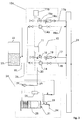
- Figure 3 shows a modular circuit in which several Pressure maintaining devices 10 and 10a additionally with a known degassing and make-up device 24 connected are. There are inflow 26 and outflow lines 18 of the devices 10, 10a and 24 with each other connected, which allows shared access to the Storage vessel 22 is possible. The overflow lines also conduct 17 and 17a the water 23 in the storage vessel 22.
- the drain 27 of the degassing device 24 is direct with the connecting piece 20 of the fresh water supply Pressure maintenance station 10 connected. There is also an option Integration of the inflow 26 and the outflow 27 directly possible in the water cycle 21.
- the controls 11, 11a and 25 are for the exchange of Information related to each other.
- the Control 11 with the controller 25 of the degassing device 24 connected to the solenoid valve 15 when activated Open the degassing function.
- the degassing process takes place in a vacuum tank 28, in which the water 23 is sprayed.
- the negative pressure is generated here by a pump 29 which Sucks water 23 out of the vacuum container 28 and in pumps the water circuit 21. Is the vacuum tank 28 pumped empty, the pump 29 is stopped. The flowing through the vacuum into the vacuum container 28 Water pushes the released gas through Degassing valve 31 out of the vacuum tank 28.
- the pressure maintaining devices 10 and 10a are additional connected by their controls 11 and 11a, to support themselves in their functions. So the pressure holding devices 10 and 10a exchange information to control their pumps 14 and 14a, thereby a double output is achieved. As well the pressure holding devices 10 and 10a exchange information to control the solenoid valves 15 and 15a out, whereby the pressure P in the water circuit 21 faster can be broken down. Likewise, more water can 23 be provided for the degassing process.
Landscapes
- Engineering & Computer Science (AREA)
- Physics & Mathematics (AREA)
- Thermal Sciences (AREA)
- Chemical & Material Sciences (AREA)
- Combustion & Propulsion (AREA)
- Mechanical Engineering (AREA)
- General Engineering & Computer Science (AREA)
- Degasification And Air Bubble Elimination (AREA)
- Control Of Fluid Pressure (AREA)
- Physical Water Treatments (AREA)
- Safety Valves (AREA)
Applications Claiming Priority (2)
| Application Number | Priority Date | Filing Date | Title |
|---|---|---|---|
| DE19740358A DE19740358C2 (de) | 1997-09-13 | 1997-09-13 | Druckhaltevorrichtung |
| DE19740358 | 1997-09-13 |
Publications (2)
| Publication Number | Publication Date |
|---|---|
| EP0902239A2 true EP0902239A2 (fr) | 1999-03-17 |
| EP0902239A3 EP0902239A3 (fr) | 2001-04-25 |
Family
ID=7842289
Family Applications (1)
| Application Number | Title | Priority Date | Filing Date |
|---|---|---|---|
| EP98114439A Withdrawn EP0902239A3 (fr) | 1997-09-13 | 1998-08-01 | Dispositif de maintien de pression à commande par fluide |
Country Status (4)
| Country | Link |
|---|---|
| EP (1) | EP0902239A3 (fr) |
| CZ (1) | CZ290696B6 (fr) |
| DE (1) | DE19740358C2 (fr) |
| PL (1) | PL328543A1 (fr) |
Cited By (6)
| Publication number | Priority date | Publication date | Assignee | Title |
|---|---|---|---|---|
| EP1855060A3 (fr) * | 2006-05-11 | 2010-06-02 | Reflex Winkelmann GmbH & Co. KG | Procédé de dégazage et/ou de maintien de la pression dans un circuit d'eau fermé |
| WO2011110946A3 (fr) * | 2010-03-11 | 2013-08-08 | Schweyher, Holger | Circuit d'échange de chaleur |
| CN106801912A (zh) * | 2017-02-06 | 2017-06-06 | 青岛海信日立空调系统有限公司 | 一种热泵水暖系统的水路堵塞检测方法及装置 |
| CN106839085A (zh) * | 2017-02-24 | 2017-06-13 | 青岛海信日立空调系统有限公司 | 一种热泵水暖系统干烧判定方法及装置 |
| RU205899U1 (ru) * | 2020-11-16 | 2021-08-11 | Общество с ограниченной ответственностью "Торговый Дом АДЛ" | Устройство заполнения закрытой отопительной системы |
| WO2023203029A1 (fr) * | 2022-04-20 | 2023-10-26 | Grundfos Holding A/S | Procédé et système de dégazage de liquide |
Families Citing this family (1)
| Publication number | Priority date | Publication date | Assignee | Title |
|---|---|---|---|---|
| DE102016106061A1 (de) | 2016-04-04 | 2017-10-05 | Sinusverteiler Gmbh | Verbindungseinheit zum Verbinden einer Druckhalte- und/oder Entgasungsvorrichtung mit einem Heizkreisverteiler einer Heizungsanlage |
Citations (1)
| Publication number | Priority date | Publication date | Assignee | Title |
|---|---|---|---|---|
| DE3716396A1 (de) | 1987-05-15 | 1988-12-15 | Hans Friedrich Bernstein | Ausdehnungs- und druckhaltevorrichtung fuer zirkulierende fluessigkeitsstroeme |
Family Cites Families (2)
| Publication number | Priority date | Publication date | Assignee | Title |
|---|---|---|---|---|
| AT401293B (de) * | 1994-01-14 | 1996-07-25 | Schwarz A & Co | Verfahren und vorrichtung zur entgasung der flüssigkeit in einem flüssigkeitskreislauf |
| DE4430799C1 (de) * | 1994-08-30 | 1995-10-26 | Reflex Winkelmann & Pannhoff G | Verfahren und Vorrichtung zur Vakuumentgasung von Heizungswasser aus einem Heizungsnetz |
-
1997
- 1997-09-13 DE DE19740358A patent/DE19740358C2/de not_active Expired - Fee Related
-
1998
- 1998-08-01 EP EP98114439A patent/EP0902239A3/fr not_active Withdrawn
- 1998-08-31 CZ CZ19982767A patent/CZ290696B6/cs not_active IP Right Cessation
- 1998-09-11 PL PL98328543A patent/PL328543A1/xx unknown
Patent Citations (1)
| Publication number | Priority date | Publication date | Assignee | Title |
|---|---|---|---|---|
| DE3716396A1 (de) | 1987-05-15 | 1988-12-15 | Hans Friedrich Bernstein | Ausdehnungs- und druckhaltevorrichtung fuer zirkulierende fluessigkeitsstroeme |
Cited By (7)
| Publication number | Priority date | Publication date | Assignee | Title |
|---|---|---|---|---|
| EP1855060A3 (fr) * | 2006-05-11 | 2010-06-02 | Reflex Winkelmann GmbH & Co. KG | Procédé de dégazage et/ou de maintien de la pression dans un circuit d'eau fermé |
| WO2011110946A3 (fr) * | 2010-03-11 | 2013-08-08 | Schweyher, Holger | Circuit d'échange de chaleur |
| CN106801912A (zh) * | 2017-02-06 | 2017-06-06 | 青岛海信日立空调系统有限公司 | 一种热泵水暖系统的水路堵塞检测方法及装置 |
| CN106839085A (zh) * | 2017-02-24 | 2017-06-13 | 青岛海信日立空调系统有限公司 | 一种热泵水暖系统干烧判定方法及装置 |
| CN106839085B (zh) * | 2017-02-24 | 2019-04-16 | 青岛海信日立空调系统有限公司 | 一种热泵水暖系统干烧判定方法及装置 |
| RU205899U1 (ru) * | 2020-11-16 | 2021-08-11 | Общество с ограниченной ответственностью "Торговый Дом АДЛ" | Устройство заполнения закрытой отопительной системы |
| WO2023203029A1 (fr) * | 2022-04-20 | 2023-10-26 | Grundfos Holding A/S | Procédé et système de dégazage de liquide |
Also Published As
| Publication number | Publication date |
|---|---|
| DE19740358C2 (de) | 2001-03-08 |
| DE19740358A1 (de) | 1999-04-01 |
| CZ276798A3 (cs) | 2000-03-15 |
| PL328543A1 (en) | 1999-03-01 |
| EP0902239A3 (fr) | 2001-04-25 |
| CZ290696B6 (cs) | 2002-09-11 |
Similar Documents
| Publication | Publication Date | Title |
|---|---|---|
| DE2748079C2 (de) | Wasserdruck-Verstärkungsanlage | |
| EP2187136A2 (fr) | Procédé de fonctionnement d'un système de transport d'énergie thermique sur un support fluide | |
| DE4108915A1 (de) | Hydraulische einrichtung zur druckmittelversorgung eines bevorrechtigten primaerlastkreises | |
| EP0902239A2 (fr) | Dispositif de maintien de pression à commande par fluide | |
| EP4382814A1 (fr) | Dispositif d'écoulement pour l'équipement ultérieur d'une installation de chauffage et installation de chauffage | |
| DE2227898A1 (de) | Leistungsuebertragung | |
| DE3420674C2 (de) | Druckversorgungseinrichtung für ein Hydrauliksystem | |
| DE2141000A1 (de) | Vorrichtung und Verfahren zur Überwachung eines unter Druck stehenden Flüssigkeitssystems | |
| EP0736214B1 (fr) | Systeme d'alimentation de securite et de traitement au bore pour un reacteur a eau sous pression permettant le procede de fonctionnement dudit systeme | |
| DE10244256B4 (de) | Heizanlage und/oder Kühlanlage mit mindestens einer Wärmequelle | |
| DE2300194A1 (de) | Brennstoffregelsystem | |
| DE2154900C2 (de) | Druckhalteeinrichtung für geschlossene Heizsysteme | |
| DE10306756A1 (de) | Hydropneumatische Federungseinrichtung für Fahrzeuge | |
| CH696154A5 (de) | Heizanlage oder Kühlanlage | |
| EP0667223B1 (fr) | Dispositif pour générer de l'azote à haute pression | |
| EP1382908B1 (fr) | Dispositif de commande de débit d'un gaz | |
| EP0065033A2 (fr) | Installation de chauffage pour chauffage urbain | |
| DE2023660A1 (de) | Hydraulikanordnung | |
| DE4414596B4 (de) | Druckmittelanlage mit wenigstens zwei Verbraucherkreisen | |
| EP0492068A2 (fr) | Installation à air comprimé munie d'une partie à haute pression et d'une partie à basse pression | |
| DE4203323C2 (de) | Hydraulischer Drehmomentwandler mit Überbrückungskupplung | |
| DE4336237C2 (de) | Verfahren zur Zu- und Ableitung von Kondensat und Wasser-Dampf-Kreislauf | |
| EP1515049B1 (fr) | Commande hydraulique | |
| DE69803828T2 (de) | Wassergesteuerter Heisswassererzeuger | |
| DE69204524T2 (de) | Notkühlungsspeicher für Kernreaktor. |
Legal Events
| Date | Code | Title | Description |
|---|---|---|---|
| PUAI | Public reference made under article 153(3) epc to a published international application that has entered the european phase |
Free format text: ORIGINAL CODE: 0009012 |
|
| AK | Designated contracting states |
Kind code of ref document: A2 Designated state(s): AT BE CH CY DE DK ES FI FR GB GR IE IT LI LU MC NL PT SE |
|
| AX | Request for extension of the european patent |
Free format text: AL;LT;LV;MK;RO;SI |
|
| PUAL | Search report despatched |
Free format text: ORIGINAL CODE: 0009013 |
|
| AK | Designated contracting states |
Kind code of ref document: A3 Designated state(s): AT BE CH CY DE DK ES FI FR GB GR IE IT LI LU MC NL PT SE |
|
| AX | Request for extension of the european patent |
Free format text: AL;LT;LV;MK;RO;SI |
|
| RAP1 | Party data changed (applicant data changed or rights of an application transferred) |
Owner name: REFLEX WINKELMANN + PANNHOFF GMBH + CO. |
|
| 17P | Request for examination filed |
Effective date: 20010818 |
|
| AKX | Designation fees paid |
Free format text: AT BE CH CY DE DK ES FI FR GB GR IE IT LI LU MC NL PT SE |
|
| GRAH | Despatch of communication of intention to grant a patent |
Free format text: ORIGINAL CODE: EPIDOS IGRA |
|
| STAA | Information on the status of an ep patent application or granted ep patent |
Free format text: STATUS: THE APPLICATION IS DEEMED TO BE WITHDRAWN |
|
| 18D | Application deemed to be withdrawn |
Effective date: 20030301 |