EP0902239A2 - Fluid actuated pressure control device - Google Patents
Fluid actuated pressure control device Download PDFInfo
- Publication number
- EP0902239A2 EP0902239A2 EP98114439A EP98114439A EP0902239A2 EP 0902239 A2 EP0902239 A2 EP 0902239A2 EP 98114439 A EP98114439 A EP 98114439A EP 98114439 A EP98114439 A EP 98114439A EP 0902239 A2 EP0902239 A2 EP 0902239A2
- Authority
- EP
- European Patent Office
- Prior art keywords
- pressure
- valve
- pump
- water
- maintaining device
- Prior art date
- Legal status (The legal status is an assumption and is not a legal conclusion. Google has not performed a legal analysis and makes no representation as to the accuracy of the status listed.)
- Withdrawn
Links
Images

Classifications
-
- F—MECHANICAL ENGINEERING; LIGHTING; HEATING; WEAPONS; BLASTING
- F24—HEATING; RANGES; VENTILATING
- F24D—DOMESTIC- OR SPACE-HEATING SYSTEMS, e.g. CENTRAL HEATING SYSTEMS; DOMESTIC HOT-WATER SUPPLY SYSTEMS; ELEMENTS OR COMPONENTS THEREFOR
- F24D19/00—Details
- F24D19/08—Arrangements for drainage, venting or aerating
- F24D19/082—Arrangements for drainage, venting or aerating for water heating systems
- F24D19/083—Venting arrangements
-
- F—MECHANICAL ENGINEERING; LIGHTING; HEATING; WEAPONS; BLASTING
- F24—HEATING; RANGES; VENTILATING
- F24D—DOMESTIC- OR SPACE-HEATING SYSTEMS, e.g. CENTRAL HEATING SYSTEMS; DOMESTIC HOT-WATER SUPPLY SYSTEMS; ELEMENTS OR COMPONENTS THEREFOR
- F24D3/00—Hot-water central heating systems
- F24D3/04—Hot-water central heating systems with the water under high pressure
- F24D3/06—Arrangements or devices for maintaining high pressure
Definitions
- the invention relates to a pressure maintaining device for Regulation of the pressure of a liquid, in particular of Water in a water cycle, and for degassing the Liquid in a storage vessel, with a first, the pressure reducing valve, with a control, that controls the first valve and the one that Vacuum compensating pump depending on the Regulates pressure in the water circuit and with a second one Safety valve, that with the overpressure reducing Valve is connected in series.
- Such liquid-controlled pressure maintenance stations are used for pressure maintenance, volume compensation and in increasingly with integrated make-up and degassing within heating and cooling water systems used.
- the valves must have a high level of reliability possess, so the risk of idling the system is avoided.
- DIN 4751 T2 relates to external pressure monitoring accordingly sections 10.4 and 10.3.2 using a TÜV-tested minimum pressure limiter. Around To meet requirements is separate monitoring and a correspondingly expensive control of both Valves necessary.
- the valve for minimum pressure relief is also designed as a solenoid valve that if there is no voltage and if the Minimum pressure limiter is closed.
- the one described Setup with two solenoid valves requires an additional, expensive wiring according to DIN VDE 0116.
- DE 37 16 396 A1 describes a device for degassing of liquid, especially heating water, known with a controller that when a certain pressure levels a valve opens to liquid from the pressure circuit into a pressure compensation vessel to lead. When falling below a certain Pressure levels are controlled by a pump that draws the liquid from the pressure compensation vessel into the liquid circuit pumped back.
- the object of the present invention is to provide an inexpensive easy to manufacture pressure maintenance device to create the drainage of liquid at a Minimum pressure drop that prevents the control characteristic improved and if necessary with further pressure maintenance devices connected together in a modular manner can be.
- the safety valve is a mechanical relief valve that is if the minimum operating pressure in the water circuit is undershot automatically closes, and that the pump and the overflow valve are coordinated that during the degassing in the storage vessel with the open a normal pressure in the first valve in the water circuit prevails.
- the pressure maintaining device has an overflow line and a discharge line into the water cycle on, with the first valve in the flow direction arranged after the overflow valve in the overflow line is.
- the pump is assigned to the discharge line.
- the first valve is a solenoid valve from a control depending on the pressure in the water cycle is controlled.
- the pump is dependent on the controller regulated by the pressure in the water cycle.
- the control opens the solenoid valve when the pressure in the water circuit exceeds a certain value and closes the solenoid valve when the pressure in the water circuit reached normal pressure.
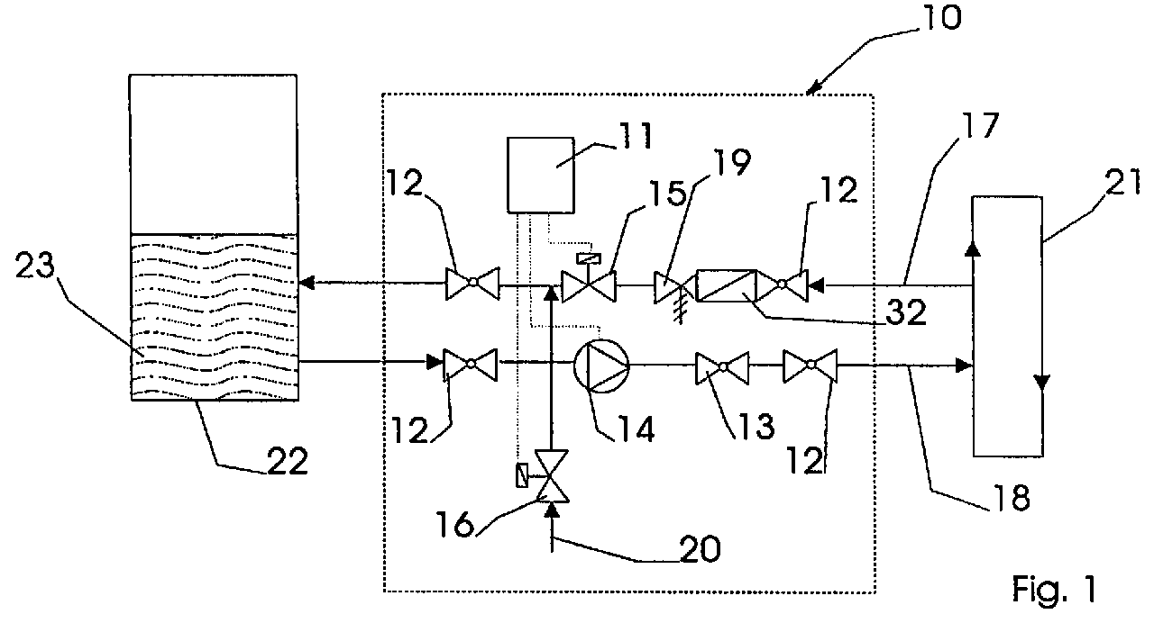
- the pressure maintaining device shown in Figure 1 10 has a controller 11, which has a solenoid valve 15 and controls a pump 14. Preferably regulates the Control 11 the fresh water supply through a fresh water inlet 20 with a solenoid valve 16, the lack of water is opened.
- the preferred liquid is Water used.
- the fresh water supply can 20 with the solenoid valve 16 omitted.
- the pressure maintaining device 10 is between an overflow line 17 and an outflow line 18 are arranged.
- Both lines 17 and 18 open into a storage vessel 22, which is preferably an unpressurized expansion vessel is.
- the outflow line 18 and the overflow line 17 are connected to a water circuit 21, the one Plenty of - not shown - consumers with Liquid, i.e. water 23 supplied.
- the controller 11 opens the solenoid valve 15 at a pressure P, which is normally above the normal pressure P.
- the solenoid valve 15 remains open as long is energized until the pressure P in the water circuit 21 to the value P to which in turn is identical to the value P normal.
- the control 11 starts the pump 14. Water 23 is pumped from the storage vessel 22 into the water circuit 21 until the normal pressure P is reached normally .
- the pump 21 is started at a predetermined pressure P a, which is normally below atmospheric pressure P.
- the pump is switched off on reaching the pressure P.
- the pressure P out corresponds to the pressure P normal .
- an overflow valve 19 is in front of the solenoid valve 15 in the flow direction.
- the overflow valve 19 is preferably operated by spring force. Other kinds the control are also conceivable. By mechanical Execution is the function of the overflow valve 19 also ensured in the event of a power failure.
- the overflow valve 19 assumes a safety function in the event that the solenoid valve 15 cannot be closed. If, due to the failure of the solenoid valve 15, the pressure P in the water circuit 21 drops to the value P O , the spring pressure of the overflow valve 19 is sufficient to close the outflow line 18.
- the value P O is lower than the pressure value P a, so that the activation of the pump 14 is not excluded.
- the overflow valve 19 preferably has adjusting means (not shown) for determining the spring pressure.
- the use of an automatically closing overflow valve 19 increases the safety as a result of the pressure falling below the minimum pressure P O.
- the open-close control characteristic of the solenoid valve 15 is also improved by the P behavior of the overflow valve 19.
- the P behavior leads to a softer driving style of the device.
- the large switching hysteresis usually of the mechanical relief valve 19 does not lead to an increase in the Truhysteres on p - p, which bar can be adjusted to greater than or equal to 0.2 by the controller. 11
- pump 14 and overflow valve 19 are matched to one another such that a pressure close to P normal is set automatically when the solenoid valve 15 is open and after the pump 14 is switched on.
- the tuning takes place on the one hand by changing the spring force acting on the overflow valve 19, and on the other hand by tuning the valve seat (not shown).
- the closing point setting P O must be taken into account.
- a dirt trap 32 protects the solenoid valve and the downstream devices.
- Figure 3 shows a modular circuit in which several Pressure maintaining devices 10 and 10a additionally with a known degassing and make-up device 24 connected are. There are inflow 26 and outflow lines 18 of the devices 10, 10a and 24 with each other connected, which allows shared access to the Storage vessel 22 is possible. The overflow lines also conduct 17 and 17a the water 23 in the storage vessel 22.
- the drain 27 of the degassing device 24 is direct with the connecting piece 20 of the fresh water supply Pressure maintenance station 10 connected. There is also an option Integration of the inflow 26 and the outflow 27 directly possible in the water cycle 21.
- the controls 11, 11a and 25 are for the exchange of Information related to each other.
- the Control 11 with the controller 25 of the degassing device 24 connected to the solenoid valve 15 when activated Open the degassing function.
- the degassing process takes place in a vacuum tank 28, in which the water 23 is sprayed.
- the negative pressure is generated here by a pump 29 which Sucks water 23 out of the vacuum container 28 and in pumps the water circuit 21. Is the vacuum tank 28 pumped empty, the pump 29 is stopped. The flowing through the vacuum into the vacuum container 28 Water pushes the released gas through Degassing valve 31 out of the vacuum tank 28.
- the pressure maintaining devices 10 and 10a are additional connected by their controls 11 and 11a, to support themselves in their functions. So the pressure holding devices 10 and 10a exchange information to control their pumps 14 and 14a, thereby a double output is achieved. As well the pressure holding devices 10 and 10a exchange information to control the solenoid valves 15 and 15a out, whereby the pressure P in the water circuit 21 faster can be broken down. Likewise, more water can 23 be provided for the degassing process.
Landscapes
- Engineering & Computer Science (AREA)
- Physics & Mathematics (AREA)
- Thermal Sciences (AREA)
- Chemical & Material Sciences (AREA)
- Combustion & Propulsion (AREA)
- Mechanical Engineering (AREA)
- General Engineering & Computer Science (AREA)
- Degasification And Air Bubble Elimination (AREA)
- Control Of Fluid Pressure (AREA)
- Physical Water Treatments (AREA)
- Safety Valves (AREA)
Abstract
Druckhaltevorrichtung (10) zur Regelung des Drucks (P)
einer Flüssigkeit (23) in einem Wasserkreislauf (21),
mit einem ersten den Überdruck reduzierenden Ventil
(15), mit einem zweiten Sicherheitsventil (19) und mit
einer den Unterdruck ausgleichenden Pumpe (14). Das Sicherheitsventil
ist ein in Reihe mit dem ersten Ventil
(15) geschaltetes Überströmventil (19), das sich ab Unterschreiten
eines Mindestbetriebsdruckes (Po) im Wasserkreislauf
(21) selbsttätig schließt. Die Einstellung
bewirkt bei laufender Pumpe (14) und geöffnetem Magnetventil
(15) gleichzeitig eine Druckregulierung auf
Normaldruck.
Description
Die Erfindung betrifft eine Druckhaltevorrichtung zur Regelung des Drucks einer Flüssigkeit, insbesondere von Wasser in einem Wasserkreislauf, und zur Entgasung der Flüssigkeit in einem Speichergefäß, mit einem ersten, den Überdruck reduzierenden Ventil, mit einer Steuerung, die das erste Ventil steuert und die eine, den Unterdruck ausgleichende Pumpe in Abhängigkeit vom Druck im Wasserkreislauf regelt und mit einem zweiten Sicherungsventil, das mit dem den Überdruck reduzierenden Ventil in Reihe geschaltet ist.The invention relates to a pressure maintaining device for Regulation of the pressure of a liquid, in particular of Water in a water cycle, and for degassing the Liquid in a storage vessel, with a first, the pressure reducing valve, with a control, that controls the first valve and the one that Vacuum compensating pump depending on the Regulates pressure in the water circuit and with a second one Safety valve, that with the overpressure reducing Valve is connected in series.
Derartige flüssigkeitsgesteuerte Druckhaltestationen werden zur Druckhaltung, zum Volumenausgleich und in zunehmendem Maße mit integrierter Nachspeisung und Entgasung innerhalb von Heizungs- und Kühlwassersystemen eingesetzt. Hierbei müssen die Ventile eine hohe Zuverlässigkeit besitzen, damit die Gefahr des Leerlaufens der Anlage vermieden wird. Such liquid-controlled pressure maintenance stations are used for pressure maintenance, volume compensation and in increasingly with integrated make-up and degassing within heating and cooling water systems used. The valves must have a high level of reliability possess, so the risk of idling the system is avoided.
Nach DIN 4751 T2, Abschnitt 10.3.2, wird insbesondere bei Wasserheizungsanlagen, die eine Vorlauftemperatur von über 100°C haben können, ein zusätzliches Sicherheitsventil gefordert.According to DIN 4751 T2, Section 10.3.2, in particular in water heating systems that have a flow temperature an additional safety valve required.
Die DIN 4751 T2 betrifft eine Fremddrucküberwachung entsprechend den Abschnitten 10.4 und 10.3.2 unter Verwendung eines TÜV-geprüften Mindestdruckbegrenzers. Um diese Anforderungen zu erfüllen, ist eine separate Überwachung und eine entsprechend kostenintensive Steuerung beider Ventile notwendig. Das Ventil zur Mindestdruckabsicherung ist hierbei ebenfalls als Magnetventil ausgebildet, das bei fehlender Stromspannung sowie bei Ansprechen des Mindestdruckbegrenzers geschlossen wird. Der beschriebene Aufbau mit zwei Magnetventilen bedarf einer zusätzlichen, teuren Verdrahtung nach DIN VDE 0116.DIN 4751 T2 relates to external pressure monitoring accordingly sections 10.4 and 10.3.2 using a TÜV-tested minimum pressure limiter. Around To meet requirements is separate monitoring and a correspondingly expensive control of both Valves necessary. The valve for minimum pressure relief is also designed as a solenoid valve that if there is no voltage and if the Minimum pressure limiter is closed. The one described Setup with two solenoid valves requires an additional, expensive wiring according to DIN VDE 0116.
Aus der DE 37 16 396 A1 ist eine Vorrichtung zur Entgasung von Flüssigkeit, insbesondere von Heizungswasser, mit einer Steuerung bekannt, die beim Überschreiten eines bestimmten Druckniveaus ein Ventil öffnet, um Flüssigkeit aus dem Druckkreislauf in ein Druckausgleichsgefäß zu leiten. Bei Unterschreiten eines bestimmten Druckniveaus wird eine Pumpe angesteuert, die die Flüssigkeit aus dem Druckausgleichsgefäß in den Flüssigkeitskreislauf zurückpumpt.DE 37 16 396 A1 describes a device for degassing of liquid, especially heating water, known with a controller that when a certain pressure levels a valve opens to liquid from the pressure circuit into a pressure compensation vessel to lead. When falling below a certain Pressure levels are controlled by a pump that draws the liquid from the pressure compensation vessel into the liquid circuit pumped back.
Bei einer Druckhaltevorrichtung, die gleichzeitig einen Teilstrom des Wasserkreislaufes entgast, muß darüber hinaus der dem System zufließende Volumenstrom gleich dem abströmenden Volumenstrom sein. Durch dieses ausgeglichene Verhältnis kann sich ein stabiler Druck im Wasserkreislauf aufbauen.In the case of a pressure-maintaining device which simultaneously has a Degassed partial flow of the water cycle must above In addition, the volume flow flowing into the system is the same the outflowing volume flow. Through this balanced Ratio can be a stable pressure in the Build up water cycle.
Aufgabe der vorliegenden Erfindung ist es, eine kostengünstige, einfach herzustellende Druckhaltevorrichtung zu schaffen, die den Abfluß von Flüssigkeit bei einer Mindestdruckunterschreitung verhindert, die die Regelcharakteristik verbessert und die im Bedarfsfall mit weiteren Druckhaltevorrichtungen modular zusammengeschaltet werden kann.The object of the present invention is to provide an inexpensive easy to manufacture pressure maintenance device to create the drainage of liquid at a Minimum pressure drop that prevents the control characteristic improved and if necessary with further pressure maintenance devices connected together in a modular manner can be.
Gelöst wird diese Aufgabe dadurch, daß das Sicherungsventil ein mechanisches Überströmventil ist, das sich bei Unterschreiten eines Mindestbetriebsdruckes im Wasserkreislauf selbsttätig schließt, und daß die Pumpe und das Überströmventil so aufeinander abgestimmt sind, daß während der Entgasung im Speichergefäß bei geöffnetem ersten Ventil im Wasserkreislauf ein Normaldruck herrscht.This problem is solved in that the safety valve is a mechanical relief valve that is if the minimum operating pressure in the water circuit is undershot automatically closes, and that the pump and the overflow valve are coordinated that during the degassing in the storage vessel with the open a normal pressure in the first valve in the water circuit prevails.
Weiterhin weist die Druckhaltevorrichtung eine Überströmleitung aus und eine Abströmleitung in den Wasserkreislauf auf, wobei das erste Ventil in Fließrichtung nach dem Überströmventil in der Überströmleitung angeordnet ist. Die Pumpe ist der Abströmleitung zugeordnet. Dabei ist das erste Ventil ein Magnetventil, das von einer Steuerung in Abhängigkeit von dem Druck in dem Wasserkreislauf gesteuert wird.Furthermore, the pressure maintaining device has an overflow line and a discharge line into the water cycle on, with the first valve in the flow direction arranged after the overflow valve in the overflow line is. The pump is assigned to the discharge line. The first valve is a solenoid valve from a control depending on the pressure in the water cycle is controlled.
Ferner wird die Pumpe durch die Steuerung in Abhängigkeit vom Druck im Wasserkreislauf geregelt. Die Steuerung öffnet das Magnetventil, wenn der Druck im Wasserkreislauf einen bestimmten Wert überschreitet und schließt das Magnetventil, wenn der Druck im Wasserkreislauf den Normaldruck erreicht.Furthermore, the pump is dependent on the controller regulated by the pressure in the water cycle. The control opens the solenoid valve when the pressure in the water circuit exceeds a certain value and closes the solenoid valve when the pressure in the water circuit reached normal pressure.
Die Steuerungen der Druckhaltevorrichtungen tauschen dabei Informationen zur Steuerung der Pumpen und der Magnetventile aus. Hierdurch braucht nur eine Entgasungsvorrichtung mit einer der Druckhaltevorrichtungen verbunden werden, während alle möglichen weiteren von der ersten Druckhaltevorrichtung mit den nötigen Informationen versorgt werden.Replace the pressure control device controls thereby information about the control of the pumps and the Solenoid valves off. This only requires a degassing device with one of the pressure maintenance devices be connected while all sorts of other of the first pressure maintenance device with the necessary information be supplied.
Weitere vorteilhafte Maßnahmen sind in den Unteransprüchen beschrieben. Die Erfindung ist in der beiliegenden Zeichnung dargestellt und wird nachfolgend näher beschrieben; es zeigt:
- Figur 1
- den schematischen Aufbau einer Druckhaltevorrichtung, mit einer Steuerung, mit einem Magnetventil in einer Überströmleitung mit einem Überströmventil, mit einem Speichergefäß, mit einer Abströmleitung, in der eine Pumpe angeordnet ist und mit einem Frischwasserzulauf;
- Figur 2
- ein Schaltpunktdiagramm, das die Schaltzustände der Pumpe, des Überströmventils und des Magnetventils in Abhängigkeit vom Druck im Wasserkreislauf darstellt;
- Figur 3
- eine modulare Verschaltung von mehreren Druckhaltevorrichtungen und einer Entgasungsvorrichtung.
- Figure 1
- the schematic structure of a pressure maintaining device, with a control, with a solenoid valve in an overflow line with an overflow valve, with a storage vessel, with an outflow line in which a pump is arranged and with a fresh water inlet;
- Figure 2
- a switching point diagram illustrating the switching states of the pump, the relief valve and the solenoid valve as a function of the pressure in the water circuit;
- Figure 3
- a modular connection of several pressure maintenance devices and a degassing device.
Die in der Figur 1 dargestellte Druckhaltevorrichtung
10 weist eine Steuerung 11 auf, die ein Magnetventil 15
und eine Pumpe 14 steuert. Vorzugsweise regelt die
Steuerung 11 die Frischwasserzufuhr durch einen Frischwasserzulauf
20 mit einem Magnetventil 16, das bei Wassermangel
geöffnet wird. Als Flüssigkeit wird vorzugsweise
Wasser verwendet. In Kombination mit einer Entgasungs- und Nachspeisvorrichtung 24 kann der Frischwasserzulauf
20 mit dem Magnetventil 16 entfallen.The pressure maintaining device shown in Figure 1
10 has a
Die Druckhaltevorrichtung 10 ist zwischen einer Überströmleitung
17 und einer Abströmleitung 18 angeordnet. The
Beide Leitungen 17 und 18 münden in ein Speichergefäß
22, das vorzugsweise ein druckloses Ausdehnungsgefäß
ist. Die Abströmleitung 18 und die Überströmleitung 17
sind mit einem Wasserkreislauf 21 verbunden, der eine
Vielzahl von - nicht dargestellten - Verbrauchern mit
Flüssigkeit, sprich Wasser 23 versorgt.Both
Liegt ein zu hoher Druck P im Wasserkreislauf 21 vor,
so strömt das Wasser 23 durch die Überströmleitung 17
bei geöffnetem Magnetventil 15 in das Speichergefäß 22.If the pressure P in the
Wie das Schaltpunktdiagramm 30 in Figur 2 zeigt, öffnet
die Steuerung 11 das Magnetventil 15 bei einem Druck
Pauf, der oberhalb des Normaldrucks Pnormal liegt. Das Magnetventil
15 bleibt solange geöffnet, bis der Druck P
im Wasserkreislauf 21 auf den Wert Pzu abgefallen ist,
der wiederum identisch mit dem Wert Pnormal ist.How the switch point diagram in Figure 2 30, the
Liegt hingegen ein zu geringer Druck P im Wasserkreislauf
21 vor, so startet die Steuerung 11 die Pumpe 14.
Dabei wird Wasser 23 solange aus dem Speichergefäß 22
in den Wasserkreislauf 21 gepumpt, bis der Normaldruck
Pnormal erreicht ist.If, on the other hand, the pressure P in the
Wie aus der Figur 2 ersichtlich ist, wird die Pumpe 21
bei einem vorbestimmten Druck Pein gestartet, der unterhalb
des Normaldrucks Pnormal liegt. Die Pumpe wird beim
Erreichen des Drucks Paus abgeschaltet. Der Druck Paus
entspricht dem Druck Pnormal. Durch die Identität der
Druckwerte
Zusätzlich ist in Fließrichtung vor dem Magnetventil 15
ein erfindungsgemäßes Überströmventil 19 als Sicherheitsventil
angeordnet. Das Überströmventil 19 wird
vorzugsweise durch Federkraft betätigt. Andere Arten
der Steuerung sind ebenfalls denkbar. Durch die mechanische
Ausführung wird die Funktion des Überströmventils
19 auch bei einem Stromausfall sichergestellt.In addition, is in front of the
Das Überströmventil 19 übernimmt eine Sicherheitsfunktion
für den Fall, daß das Magnetventil 15 nicht geschlossen
werden kann. Fällt aufgrund des Ausfalls des
Magnetventils 15 der Druck P im Wasserkreislauf 21 auf
den Wert PO, so ist der Federdruck des Überströmventils
19 ausreichend, um die Abströmleitung 18 zu schließen.The
Der Wert PO ist niedriger als der Druckwert Pein, damit
die Aktivierung der Pumpe 14 nicht ausgeschlossen wird.
Der Druckwert PO ergibt sich vorzugsweise aus der Gleichung:
Durch die Verwendung eines selbsttätig schließenden
Überströmventils 19 wird die Sicherheit in Folge des
Unterschreitens des Mindestdrucks PO erhöht. Es wird
ebenfalls die Auf-Zu-Regelcharakteristik des Magnetventils
15 durch das P-Verhalten des Überströmventils 19
verbessert. Das P-Verhalten führt zu einer weicheren
Fahrweise der Vorrichtung.The use of an automatically closing
Die in der Regel große Schalthysterese des mechanischen
Überströmventils 19 führt nicht zu einer Erhöhung der
Gesamthysteres pauf - pein, die auf größer gleich 0,2 bar
durch die Steuerung 11 eingestellt werden kann.The large switching hysteresis usually of the
Für die Entgasungsfunktion werden Pumpe 14 und Überströmventil
19 so aufeinander abgestimmt, daß sich bei
geöffnetem Magnetventil 15 und nach Einschalten der
Pumpe 14 selbständig ein Druck nahe Pnormal einstellt.
Durch die Abstimmung des Überströmventils 19 ist eine
atmosphärische Teilstromentgasung über das Speichergefäß
22 möglich. Die Abstimmung erfolgt einerseits durch
Veränderung der Federkraft, die auf das Überströmventil
19 wirkt, und andererseits durch die Abstimmung des -
nicht dargestellten - Ventilsitzes. Bei der Abstimmung
ist jedoch die Schließpunkteinstellung PO zu berücksichtigen.For the degassing function,
Zur Vermeidung von unkontrollierten Rückflüssen sind
eine Reihe von Absperrventilen 12 und Rückschlagventilen
13 in den Überström- und Abströmleitungen 17 und 18
angeordnet. Ein Schmutzfänger 32 schützt das Magnetventil
und die nachgeschalteten Vorrichtungen.To avoid uncontrolled backflows
a series of shut-off
Figur 3 zeigt eine modulare Schaltung, bei der mehrere
Druckhaltevorrichtungen 10 und 10a zusätzlich mit einer
bekannten Entgasungs- und Nachspeisevorrichtung 24 verbunden
sind. Hierbei stehen Zufluß 26 und Abströmleitungen
18 der Vorrichtungen 10, 10a und 24 miteinander
in Verbindung, wodurch ein gemeinsamer Zugriff auf das
Speichergefäß 22 möglich ist. Ebenso leiten die Überströmleitungen
17 und 17a die Wasser 23 in das Speichergefäß
22.Figure 3 shows a modular circuit in which several
Der Abfluß 27 der Entgasungsvorrichtung 24 ist direkt
mit dem Anschlußstutzen 20 des Frischwasserzulaufs der
Druckhaltestation 10 verbunden. Wahlweise ist auch eine
Einbindung des Zuflusses 26 und des Abflusses 27 direkt
in den Wasserkreislauf 21 möglich.The drain 27 of the
Die Steuerungen 11, 11a und 25 stehen zum Austausch von
Informationen miteinander in Verbindung. Dabei ist die
Steuerung 11 mit der Steuerung 25 der Entgasungsvorrichtung
24 verbunden, um das Magnetventil 15 bei aktivierter
Entgasungsfunktion zu öffnen. The
Der Entgasungsvorgang erfolgt in einem Unterdruckbehälter
28, in dem das Wasser 23 versprüht wird. Der Unterdruck
wird hierbei durch eine Pumpe 29 erzeugt, die das
Wasser 23 aus dem Unterdruckbehälter 28 absaugt und in
den Wasserkreislauf 21 pumpt. Ist der Unterdruckbehälter
28 leer gepumpt, wird die Pumpe 29 gestoppt. Das
durch das Vakuum in den Unterdruckbehälter 28 nachströmende
Wasser drückt das freigesetzte Gas durch ein
Entgasungsventil 31 aus dem Unterdruckbehälter 28 hinaus.The degassing process takes place in a
Die Druckhaltevorrichtungen 10 und 10a sind zusätzlich
durch ihre Steuerungen 11 und 11a miteinander verbunden,
um sich in ihren Funktionen zu unterstützen. So
tauschen die Druckhaltevorrichtungen 10 und 10a Informationen
zur Steuerung ihrer Pumpen 14 und 14a aus, wodurch
eine doppelte Förderleistung erreicht wird. Ebenso
tauschen die Druckhaltevorrichtungen 10 und 10a Informationen
zur Steuerung der Magnetventile 15 und 15a
aus, wodurch der Druck P im Wasserkreislauf 21 schneller
abgebaut werden kann. Ebenso kann mehr Wasser 23
für den Entgasungsvorgang bereitgestellt werden. The
- 10, 10a10, 10a
- DruckhaltevorrichtungPressure maintenance device
- 11, 11a11, 11a
- Steuerungcontrol
- 1212th
- AbsperrventilShut-off valve
- 1313
- Rückschlagventilcheck valve
- 14, 14a14, 14a
- Pumpepump
- 15, 15a, 1615, 15a, 16
- Magnetventilmagnetic valve
- 17, 17a17, 17a
- ÜberströmleitungOverflow line
- 18, 18a18, 18a
- AbströmleitungDischarge line
- 1919th
- Überströmventil (Sicherheitsventil)Overflow valve (safety valve)
- 2020th
- Frischwasserzulauf/AnschlußFresh water supply / connection
- 2121
- WasserkreislaufWater cycle
- 2222
- SpeichergefäßStorage vessel
- 2323
- Flüssigkeit (Wasser)Liquid (water)
- 2424th
- Entgasungs- und NachspeisevorrichtungDegassing and make-up device
- 2525th
- Steuerungcontrol
- 2626
- ZuflußInflow
- 2727
- AbflußDrain
- 2828
- UnterdruckbehälterVacuum tank
- 2929
- Pumpepump
- 3030th
- SchaltpunktdiagrammShift point diagram
- 3131
- EntgasungsventilDegassing valve
- 3232
- SchmutzfängerMud flaps
- 3333
- Magnetventil NachspeisungMake-up solenoid valve
- 3434
- FrischwasserzulaufFresh water supply
- PP
- Druck im WasserkreislaufPressure in the water cycle
- Pnormal P normal
- NormaldruckNormal pressure
- Pauf P on
- Druck, bei dem das Magnetventil öffnetPressure at which the solenoid valve opens
- Pzu P to
- Druck, bei dem das Magnetventil schließtPressure at which the solenoid valve closes
- Paus P off
- Druck, bei dem die Pumpe anhältPressure at which the pump stops
- Pein P a
- Druck, bei dem die Pumpe anläuftPressure at which the pump starts
- Po P o
- Mindestbetriebsdruck, bei dem das Überströmventil schließtMinimum operating pressure at which the Overflow valve closes
Claims (12)
Applications Claiming Priority (2)
| Application Number | Priority Date | Filing Date | Title |
|---|---|---|---|
| DE19740358 | 1997-09-13 | ||
| DE19740358A DE19740358C2 (en) | 1997-09-13 | 1997-09-13 | Pressure maintenance device |
Publications (2)
| Publication Number | Publication Date |
|---|---|
| EP0902239A2 true EP0902239A2 (en) | 1999-03-17 |
| EP0902239A3 EP0902239A3 (en) | 2001-04-25 |
Family
ID=7842289
Family Applications (1)
| Application Number | Title | Priority Date | Filing Date |
|---|---|---|---|
| EP98114439A Withdrawn EP0902239A3 (en) | 1997-09-13 | 1998-08-01 | Fluid actuated pressure control device |
Country Status (4)
| Country | Link |
|---|---|
| EP (1) | EP0902239A3 (en) |
| CZ (1) | CZ290696B6 (en) |
| DE (1) | DE19740358C2 (en) |
| PL (1) | PL328543A1 (en) |
Cited By (6)
| Publication number | Priority date | Publication date | Assignee | Title |
|---|---|---|---|---|
| EP1855060A3 (en) * | 2006-05-11 | 2010-06-02 | Reflex Winkelmann GmbH & Co. KG | Method for degasification and/or pressure maintenance in a closed water cycle |
| WO2011110946A3 (en) * | 2010-03-11 | 2013-08-08 | Schweyher, Holger | Heat-exchange circuit |
| CN106801912A (en) * | 2017-02-06 | 2017-06-06 | 青岛海信日立空调系统有限公司 | The water line block detection method and device of a kind of heat pump water-heating system |
| CN106839085A (en) * | 2017-02-24 | 2017-06-13 | 青岛海信日立空调系统有限公司 | A kind of heat pump water-heating system dry combustion method decision method and device |
| RU205899U1 (en) * | 2020-11-16 | 2021-08-11 | Общество с ограниченной ответственностью "Торговый Дом АДЛ" | Closed heating system filling device |
| WO2023203029A1 (en) * | 2022-04-20 | 2023-10-26 | Grundfos Holding A/S | A method and system for degassing liquid |
Families Citing this family (1)
| Publication number | Priority date | Publication date | Assignee | Title |
|---|---|---|---|---|
| DE102016106061A1 (en) | 2016-04-04 | 2017-10-05 | Sinusverteiler Gmbh | Connection unit for connecting a pressure maintenance and / or degassing device with a heating circuit manifold of a heating system |
Citations (1)
| Publication number | Priority date | Publication date | Assignee | Title |
|---|---|---|---|---|
| DE3716396A1 (en) | 1987-05-15 | 1988-12-15 | Hans Friedrich Bernstein | EXPANSION AND PRESSURE HOLDING DEVICE FOR CIRCULATING LIQUID FLOWS |
Family Cites Families (2)
| Publication number | Priority date | Publication date | Assignee | Title |
|---|---|---|---|---|
| AT401293B (en) * | 1994-01-14 | 1996-07-25 | Schwarz A & Co | METHOD AND DEVICE FOR DEGASSING THE LIQUID IN A LIQUID CIRCUIT |
| DE4430799C1 (en) * | 1994-08-30 | 1995-10-26 | Reflex Winkelmann & Pannhoff G | Removing gas from water circulating in central heating network |
-
1997
- 1997-09-13 DE DE19740358A patent/DE19740358C2/en not_active Expired - Fee Related
-
1998
- 1998-08-01 EP EP98114439A patent/EP0902239A3/en not_active Withdrawn
- 1998-08-31 CZ CZ19982767A patent/CZ290696B6/en not_active IP Right Cessation
- 1998-09-11 PL PL98328543A patent/PL328543A1/en unknown
Patent Citations (1)
| Publication number | Priority date | Publication date | Assignee | Title |
|---|---|---|---|---|
| DE3716396A1 (en) | 1987-05-15 | 1988-12-15 | Hans Friedrich Bernstein | EXPANSION AND PRESSURE HOLDING DEVICE FOR CIRCULATING LIQUID FLOWS |
Cited By (7)
| Publication number | Priority date | Publication date | Assignee | Title |
|---|---|---|---|---|
| EP1855060A3 (en) * | 2006-05-11 | 2010-06-02 | Reflex Winkelmann GmbH & Co. KG | Method for degasification and/or pressure maintenance in a closed water cycle |
| WO2011110946A3 (en) * | 2010-03-11 | 2013-08-08 | Schweyher, Holger | Heat-exchange circuit |
| CN106801912A (en) * | 2017-02-06 | 2017-06-06 | 青岛海信日立空调系统有限公司 | The water line block detection method and device of a kind of heat pump water-heating system |
| CN106839085A (en) * | 2017-02-24 | 2017-06-13 | 青岛海信日立空调系统有限公司 | A kind of heat pump water-heating system dry combustion method decision method and device |
| CN106839085B (en) * | 2017-02-24 | 2019-04-16 | 青岛海信日立空调系统有限公司 | A method and device for judging dry burning in a heat pump plumbing system |
| RU205899U1 (en) * | 2020-11-16 | 2021-08-11 | Общество с ограниченной ответственностью "Торговый Дом АДЛ" | Closed heating system filling device |
| WO2023203029A1 (en) * | 2022-04-20 | 2023-10-26 | Grundfos Holding A/S | A method and system for degassing liquid |
Also Published As
| Publication number | Publication date |
|---|---|
| EP0902239A3 (en) | 2001-04-25 |
| CZ276798A3 (en) | 2000-03-15 |
| DE19740358C2 (en) | 2001-03-08 |
| PL328543A1 (en) | 1999-03-01 |
| DE19740358A1 (en) | 1999-04-01 |
| CZ290696B6 (en) | 2002-09-11 |
Similar Documents
| Publication | Publication Date | Title |
|---|---|---|
| DE2748079C2 (en) | Water pressure booster system | |
| DE4108915C2 (en) | Hydraulic device for supplying pressure medium to a privileged primary load circuit | |
| DE3420674C2 (en) | Pressure supply device for a hydraulic system | |
| DE19740358C2 (en) | Pressure maintenance device | |
| DE2227898A1 (en) | POWER TRANSFER | |
| DE2141000A1 (en) | Apparatus and method for monitoring a pressurized fluid system | |
| DE102022132372A1 (en) | Heating system | |
| EP0736214B1 (en) | Safety feed and borating system for a pressurised water reactor and process for operating such a system | |
| DE10244256B4 (en) | Heating system and / or cooling system with at least one heat source | |
| DE2300194A1 (en) | FUEL CONTROL SYSTEM | |
| DE2154900C2 (en) | Pressure holding device for closed heating systems | |
| DE10306756A1 (en) | Hydropneumatic suspension device for vehicles | |
| DE69012051T2 (en) | Hydraulic valve arrangement. | |
| CH696154A5 (en) | District heating system has first and second chambers linked by pressure equalization valve | |
| EP0667223B1 (en) | Apparatus for generating high pressure nitrogen | |
| EP1382908B1 (en) | Gas flow rate control device | |
| EP0065033A2 (en) | Heating installation for a distant heating system | |
| DE2023660A1 (en) | Hydraulic arrangement | |
| DE4414596B4 (en) | Pressure medium system with at least two consumer circuits | |
| EP0492068A2 (en) | Compressed air system with a high pressure part and a low pressure part | |
| DE4203323C2 (en) | Hydraulic torque converter with lock-up clutch | |
| DE4336237C2 (en) | Process for the supply and discharge of condensate and water-steam cycle | |
| EP1515049B1 (en) | Hydraulic control | |
| DE69803828T2 (en) | Water-controlled hot water generator | |
| DE69204524T2 (en) | Emergency cooling storage for nuclear reactor. |
Legal Events
| Date | Code | Title | Description |
|---|---|---|---|
| PUAI | Public reference made under article 153(3) epc to a published international application that has entered the european phase |
Free format text: ORIGINAL CODE: 0009012 |
|
| AK | Designated contracting states |
Kind code of ref document: A2 Designated state(s): AT BE CH CY DE DK ES FI FR GB GR IE IT LI LU MC NL PT SE |
|
| AX | Request for extension of the european patent |
Free format text: AL;LT;LV;MK;RO;SI |
|
| PUAL | Search report despatched |
Free format text: ORIGINAL CODE: 0009013 |
|
| AK | Designated contracting states |
Kind code of ref document: A3 Designated state(s): AT BE CH CY DE DK ES FI FR GB GR IE IT LI LU MC NL PT SE |
|
| AX | Request for extension of the european patent |
Free format text: AL;LT;LV;MK;RO;SI |
|
| RAP1 | Party data changed (applicant data changed or rights of an application transferred) |
Owner name: REFLEX WINKELMANN + PANNHOFF GMBH + CO. |
|
| 17P | Request for examination filed |
Effective date: 20010818 |
|
| AKX | Designation fees paid |
Free format text: AT BE CH CY DE DK ES FI FR GB GR IE IT LI LU MC NL PT SE |
|
| GRAH | Despatch of communication of intention to grant a patent |
Free format text: ORIGINAL CODE: EPIDOS IGRA |
|
| STAA | Information on the status of an ep patent application or granted ep patent |
Free format text: STATUS: THE APPLICATION IS DEEMED TO BE WITHDRAWN |
|
| 18D | Application deemed to be withdrawn |
Effective date: 20030301 |