EP0902233A1 - Combined pressurised atomising nozzle - Google Patents
Combined pressurised atomising nozzle Download PDFInfo
- Publication number
- EP0902233A1 EP0902233A1 EP97810662A EP97810662A EP0902233A1 EP 0902233 A1 EP0902233 A1 EP 0902233A1 EP 97810662 A EP97810662 A EP 97810662A EP 97810662 A EP97810662 A EP 97810662A EP 0902233 A1 EP0902233 A1 EP 0902233A1
- Authority
- EP
- European Patent Office
- Prior art keywords
- feed channel
- atomizing nozzle
- pressure atomizing
- nozzle
- fuel
- Prior art date
- Legal status (The legal status is an assumption and is not a legal conclusion. Google has not performed a legal analysis and makes no representation as to the accuracy of the status listed.)
- Granted
Links
Images


Classifications
-
- F—MECHANICAL ENGINEERING; LIGHTING; HEATING; WEAPONS; BLASTING
- F23—COMBUSTION APPARATUS; COMBUSTION PROCESSES
- F23L—SUPPLYING AIR OR NON-COMBUSTIBLE LIQUIDS OR GASES TO COMBUSTION APPARATUS IN GENERAL ; VALVES OR DAMPERS SPECIALLY ADAPTED FOR CONTROLLING AIR SUPPLY OR DRAUGHT IN COMBUSTION APPARATUS; INDUCING DRAUGHT IN COMBUSTION APPARATUS; TOPS FOR CHIMNEYS OR VENTILATING SHAFTS; TERMINALS FOR FLUES
- F23L7/00—Supplying non-combustible liquids or gases, other than air, to the fire, e.g. oxygen, steam
- F23L7/002—Supplying water
-
- F—MECHANICAL ENGINEERING; LIGHTING; HEATING; WEAPONS; BLASTING
- F23—COMBUSTION APPARATUS; COMBUSTION PROCESSES
- F23D—BURNERS
- F23D11/00—Burners using a direct spraying action of liquid droplets or vaporised liquid into the combustion space
- F23D11/24—Burners using a direct spraying action of liquid droplets or vaporised liquid into the combustion space by pressurisation of the fuel before a nozzle through which it is sprayed by a substantial pressure reduction into a space
- F23D11/26—Burners using a direct spraying action of liquid droplets or vaporised liquid into the combustion space by pressurisation of the fuel before a nozzle through which it is sprayed by a substantial pressure reduction into a space with provision for varying the rate at which the fuel is sprayed
-
- F—MECHANICAL ENGINEERING; LIGHTING; HEATING; WEAPONS; BLASTING
- F23—COMBUSTION APPARATUS; COMBUSTION PROCESSES
- F23D—BURNERS
- F23D11/00—Burners using a direct spraying action of liquid droplets or vaporised liquid into the combustion space
- F23D11/36—Details
- F23D11/38—Nozzles; Cleaning devices therefor
- F23D11/383—Nozzles; Cleaning devices therefor with swirl means
Definitions
- the invention relates to a combined pressure atomizer nozzle operated with liquid fuel for gas turbine burners, according to the preamble of claim 1.
- the penetration depth of the fuel spray into the combustion air is mainly due to influences the ratio of the pulse flows of combustion air and fuel. This ratio changes with the operating conditions, i.e. as a result of changes in the fuel mass flow, in the fuel pressure and in the temperature and the pressure of the burner air.
- the evaporation time of the fuel depends essentially of the atomization quality, the relative speed between Fuel and air as well as the ambient conditions such as temperature and pressure off. While the latter for the different load conditions the gas turbine process are specified, the atomization quality and the relative speed is mainly determined by the atomizing nozzle.
- DE-PS 862 599 is a combined two- or multi-stage swirl atomizer is known, but an impulse behavior unsuitable for gas turbine burners having.
- the resulting swirl spray does indeed produce very fine atomization reached, but the fuel pulse is too small to distribute sufficiently the fuel droplets in the combustion air and thus a good premix to achieve.
- the invention tries to avoid these disadvantages. It is based on the task to create a combined pressure atomizing nozzle for gas turbine burners, with an improved adjustment of the atomization quality of liquids to the respective load conditions, i.e. a good premix throughout Load range can be realized.
- the second feed channel at least two outlet openings to the outside space.
- the combined pressure atomizer nozzle designed as a multi-hole orifice nozzle with a simple, central nozzle, which besides the fine atomization of the liquid fuel also one high fuel pulse guaranteed.
- both rapid evaporation of the liquid fuel as well as a good premix of the fuel spray can be achieved with the combustion air, which is why the inventive Pressure atomizer nozzle, especially for gas turbine burners suitable is.
- a relatively simple pressure atomizer nozzle created with a small footprint, the two-tier only by the additional Introducing the outlet openings of the second feed channel is realized.
- outlet openings of the second feed channel are evenly distributed on the circumference of the nozzle body. This arrangement ensures a uniform fuel concentration in the reaction zone and therefore prevents the increased formation of nitrogen oxides.
- the first feed channel is inside a first tube and the second feed channel formed inside a second tube. Both tubes are concentric arranged to each other and are downstream from a cover to the outside completed. The cover and the first tube are made in one piece. As a result, the pressure atomizing nozzle can be installed relatively easily, by placing the second tube up to its stop on the lid on the first tube is postponed. Then the second tube and the lid become firm connected to one another, for example by welding.
- a turbulence chamber is formed.
- the Turbulence chamber is from the second feed channel separated by a partition. In the partition are off-center arranged at least two turbulence generator openings of the second feed channel.
- the turbulence generator openings are particularly advantageously offset from the outlet openings arranged of the second feed channel.
- the displacement is preferably with four turbulence generator openings or outlet openings about 45 °, so the arrangement of the turbulence openings takes place exactly in the middle between the outlet openings. This leads to a more intense, small-scale and turbulent structure, i.e. to a very fine fuel spray.
- the pressure atomizing nozzle with the additional turbulence chamber can also be installed relatively easily.
- the lid is the first
- the tube and the partition are made in one piece, so that these components together, to some extent as an insert, are inserted into the second tube can.
- the first tube and the lid for example by welding, firmly connected.
- An alternative to a simple, central nozzle is between the first feed channel and the outlet opening either a swirl chamber or a turbulence chamber educated.
- a swirl spray is used generated with a relatively wide spray cone, so that even at partial load high fuel concentration in the center of the burner and sufficient Evaporation of the fuel can be achieved.
- This also enables in the partial load range the gas turbine has a stable burner operation.
- becomes a turbulence nozzle used as a central nozzle it can with good atomization a narrower spray angle of the liquid fuel can be realized. On in this way the fuel concentration in the center of the burner can be further increased and thereby the burner operation can be additionally stabilized at partial load.
- the pressure atomizer nozzle for example, is not shown Gas turbine burner.
- the direction of flow of the work equipment is indicated by arrows.
- the gas turbine burner, not shown, which receives the pressure atomizing nozzle is designed, for example, as a double cone burner, as it is from the EP-B1-0 321 809 is known.
- the pressure atomizer nozzle is in principle also suitable for other gas turbine burners, e.g. for the from the EP-A2-0 704 657 known, from a swirl generator with a subsequent mixing section existing burner.
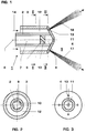
- the pressure atomizing nozzle has a nozzle body 1 two concentrically arranged tubes 2, 3, which are downstream of one conical cover 4 to an outside space 5 can be completed.
- the nozzle body 1 has a longitudinal axis 6, which with the longitudinal axis of the gas turbine burner, not shown, coincides.
- the first, inner tube 2 encloses a first, inner feed channel 7 to which connects a swirl chamber 8 downstream.
- the swirl chamber 8 is on the outside from inner tube 2, downstream of the cover 4 and upstream by an insert 9 (Fig. 1). It stands with the inner feed channel 7 above, arranged in the insert 9, tangential swirl channels 10 (FIG. 2) and with the outer space 5 via an outlet opening 11 in connection.
- the outlet opening 11 is in the Longitudinal axis 6 of the nozzle body 1 is arranged.
- the second, outer tube 3 has a larger diameter than the inner tube 2, so that between two tubes 3, 2, a second, outer and designed as an annular feed channel 12 is arranged. The latter is via four outlet openings located in the cover 4 13 also connected to the outside space 5.
- the outlet openings 13 are evenly distributed over the circumference of the nozzle body 1 (FIG. 3) and so aligned that they are in the wake of the swirl generator of the not shown Inject the burner.
- the exact orientation depends on the boundary conditions of the Gas turbine. It should be noted that the number of outlet openings 13 is not set to four, however, must be for even fuel distribution at least two outlet openings 13 are present.
- Pressure atomizer nozzle is particularly suitable for swirl generators with a conical shape suitable.
- the cover 4 and the inner tube 2 of the nozzle body 1 are formed in one piece. As a result, the entire pressure atomizing nozzle can be assembled relatively easily be by the outer tube 3 up to its stop on the lid 4 on the inner tube 2 is pushed on. Then the outer tube 3 and the lid 4 welded together.
- the pressure atomizing nozzle When operating the gas turbine burner, the pressure atomizing nozzle is considered to be atomized Liquid 14 is a liquid fuel, for example fuel oil.
- the Liquid fuel 14 to the gas turbine burner either via the outer feed channel 12 or via the inner feed channel 7 of the pressure atomizing nozzle.
- the Nozzle body 1 thus has two different nozzles, namely an outer one Multi-hole orifice nozzle and a central swirl nozzle.
- the liquid fuel 14 is in the inner feed channel 7 of the nozzle body 1 introduced from where it swirls through the swirl channels 10 into the swirl chamber 8 arrives.
- the liquid fuel 14 is then passed through the outlet opening 11 injected into the outer space 5, the swirl nozzle being a swirl spray 15 generated with a relatively wide spray cone 16 (Fig. 4).
- This also applies to Partial load a high fuel concentration in the center of the burner and a sufficient evaporation of the fuel is achieved. This also enables in Partial load range of the gas turbine stable burner operation.
- the liquid fuel is supplied centrally 14 over the center and completely from the outer feed channel 12 surrounded, inner feed channel 7.
- the inner feed channel 7 also arranged off-center and / or only partially from the outside Supply channel 12 are surrounded so that the liquid fuel 14 is decentralized, however reaches the swirl nozzle with the same effect (not shown).
- the injection pressure should be up to 100 bar.
- the maximum mass flow of liquid fuel 14 will be covered depending on Load range of the gas turbine selected and is usually less than 50% of the mass flow at full load.
- the gas turbine burner can also Work part load of the gas turbine in premix mode.
- the liquid fuel 14 is at full load in the outer feed channel 12 of the nozzle body 1 is inserted and passes through its outlet openings 13 into the outside space 5.
- the multi-hole orifice nozzle several fuel sprays corresponding to the number of outlet openings 13 17 each with a relatively narrow spray cone 18 (Fig. 1).
- the separate fuel sprays 17 have a high momentum and also have a high relative speed of the liquid fuel 14 to the combustion air. Therefore the multi-hole orifice nozzle atomizes the liquid fuel well 14.
- the liquid fuel 14 reaches a high depth of penetration into the combustion air, which leads to a significantly improved mixing quality.
- the now improved penetration depth of the liquid fuel 14 in full load operation there are no problems with partial load from wall application of Droplets of fuel oil, because then it is switched to the central swirl nozzle.
- Gas turbine burners can both use several different liquid fuels 31 as well as with a liquid fuel 31 and with water 29, with only a liquid fuel 31 or with liquid fuel-water mixtures operate. They therefore allow a relatively wide range of applications and can be adapted to changing operating conditions.
- the central swirl nozzle is in operation of the multi-hole orifice nozzle constantly by the latter flows around the liquid 14, 31. Therefore, when switching from Full to partial load, such as e.g. in the event of a loss of load, no cooling of the Swirl nozzle required so that a quick load change can be guaranteed can.
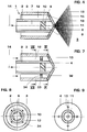
- a turbulence chamber 32 is formed.
- the turbulence chamber 32 is from the outer feed channel 12 through an intermediate wall 33 separated.
- In the intermediate wall 33 are eccentric of the outer Feed channel 12 formed four turbulence generator openings 34 (Fig. 7).
- the turbulence generator openings are 34, based on the main flow direction of the liquid fuel 14, at an angle of 45 ° to the outlet openings 13 of the outer feed channel 12 is arranged.
- This is one of the turbulence generator openings 34 in the middle between two adjacent outlet openings 13 arranged.
- the turbulent structure of the Liquid fuel 14 on the one hand more intensive and on the other hand small-scale. Therefore a turbulent, rapidly disintegrating free jet emerges from the multi-hole orifice nozzle out.
- a number other than four outlet openings 13 can also be used or turbulence generator openings 34 can be realized, in which case the described Angle changes accordingly.
- the cover 4, the inner tube 2 and the intermediate wall 33 of the nozzle body 1 are formed in one piece (Fig. 7). This also enables this pressure atomizing nozzle can be assembled relatively easily by the outer tube 3 up to its Stop on the cover 4 is pushed onto the inner tube 2. Subsequently the outer tube 3 with both the cover 4 and the partition 33 welded.
- the outlet openings 13 have of the outer feed channel 12 has a radial outlet direction 35 (FIG. 10, FIG. 11), which is particularly suitable for axial swirl generators.
- a radial outlet direction 35 (FIG. 10, FIG. 11)
- axially parallel Inflow to the pressure atomizing nozzle leads to a very high Penetration depth of the fuel spray 17 into the combustion air and thus to one additional improvement of the premixing of the gas turbine burner.
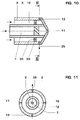
- Embodiment turbulence channels 36 arranged in the insert 9. These lead to into a turbulence chamber 37, which in turn is connected via the outlet opening 11 is connected to the outside space 5 (FIG. 12). During partial load operation, this is off a multi-hole orifice and a central turbulence nozzle Pressure atomizer nozzle becomes a rapidly disintegrating fuel spray 38 with a particularly narrow spray cone 39 generated. This can reduce the fuel concentration further increased in the center of the burner even at part load of the gas turbine become.
- the pressure atomizing nozzle can also be designed without an insert 9 so that the first feed channel 7 extends directly to the cover 4 (FIG. 13).
- a particularly simple, central nozzle with a small one is created Space requirements and an essentially analogous function to that of the central one Nozzles of the exemplary embodiments described above.
- a third Pipe 40 arranged, which ends upstream of the outlet opening 11 and the inner feed channel 7 receives.
- the first and the third tube 2, 40 are from each other spaced, so that between them a space designed as an air duct 41 arises.
- the air duct 41 widens downstream of the third pipe 40 to a mixing space 42 into which the feed channel 7 opens (FIG. 14).
- this central nozzle is via a feed line, not shown, and the Air duct 41 air 43 brought up.
- the air 43 hits the liquid fuel 14, which leads to its air-assisted injection into the outside space 5 of the pressure atomizing nozzle, i.e. into the interior of the gas turbine burner, is coming. This makes the required atomization quality independent of current fuel throughput is reached, which is particularly the case with partial load operation of Advantage is.
Landscapes
- Engineering & Computer Science (AREA)
- Chemical & Material Sciences (AREA)
- Combustion & Propulsion (AREA)
- Mechanical Engineering (AREA)
- General Engineering & Computer Science (AREA)
- Nozzles For Spraying Of Liquid Fuel (AREA)
Abstract
Aufgabe der Erfindung ist es, eine kombinierte Druckzerstäuberdüse für Gasturbinenbrenner zu schaffen, mit der eine verbesserte Anpassung der Zerstäubungsqualität von Flüssigkeiten an die jeweiligen Lastbedingungen, d.h. eine gute Vormischung über den gesamten Lastbereich realisiert werden kann. Dazu umfasst die Druckzerstäuberdüse einen Düsenkörper (1) mit zumindest zwei separaten Zuführkanälen (7, 12) für zumindest eine zu zerstäubende Flüssigkeit (14, 29, 31). Der erste Zuführkanal (7) wird zumindest teilweise vom zweiten Zuführkanal (12) umschlossen und steht stromab über eine Austrittsöffnung (11) mit einem Aussenraum (5) in Verbindung. Der zweite Zuführkanal (12) ist gleichfalls mit dem Aussenraum (5) verbunden, wobei er zumindest zwei Austrittsöffnungen (13) zum Aussenraum (5) besitzt. <IMAGE>The object of the invention is to provide a combined pressure atomizing nozzle for gas turbine burners with which an improved adaptation of the atomization quality of liquids to the respective load conditions, i.e. good premixing can be achieved over the entire load range. For this purpose, the pressure atomizing nozzle comprises a nozzle body (1) with at least two separate supply channels (7, 12) for at least one liquid (14, 29, 31) to be atomized. The first feed channel (7) is at least partially enclosed by the second feed channel (12) and is connected downstream to an outside space (5) via an outlet opening (11). The second feed channel (12) is likewise connected to the outside space (5), it having at least two outlet openings (13) to the outside space (5). <IMAGE>
Description
Die Erfindung betrifft eine mit Flüssigbrennstoff betriebene, kombinierte Druckzerstäuberdüse
für Gasturbinenbrenner, gemäss dem Oberbegriff des Anspruchs 1.The invention relates to a combined pressure atomizer nozzle operated with liquid fuel
for gas turbine burners, according to the preamble of
Eine schadstoffarme Verbrennung von flüssigen Brennstoffen, wie z.B. Heizöl extraleicht, erfordert die vollständige Verdampfung der Brennstofftropfen sowie die Vormischung des Brennstoffdampfes mit der Verbrennungsluft vor Erreichen der Flammenfront. Schon kleine Zonen mit höherer Brennstoffkonzentration führen in der Reaktionszone zu erhöhten Temperaturen und somit zur verstärkten Bildung von thermischen Stickoxiden. Ein Nachteil mager vorgemischter Flammen ist es, dass die Flammentemperaturen sehr nahe an der Löschgrenze liegen. Um bei geringer Last und somit geringerer Flammentemperatur einen weiterhin stabilen Brennerbetrieb zu realisieren, ist eine gezielte Anreicherung der Flammenstabilisierungszonen notwendig. Es besteht somit das Problem, mit einem Brenner und einer Zerstäuberdüse einen weiten Betriebsbereich der Gasturbine abzudecken.Low-pollution combustion of liquid fuels, e.g. Extra light heating oil, requires the complete evaporation of the fuel drops as well Premixing the fuel vapor with the combustion air before reaching the Flame front. Even small zones with a higher fuel concentration lead to the reaction zone to elevated temperatures and thus to increased formation of thermal nitrogen oxides. A disadvantage of lean premixed flames is that the flame temperatures are very close to the extinguishing limit. To at low load and thus lower flame temperature a stable Realizing burner operation is a targeted enrichment of the flame stabilization zones necessary. So there is the problem with a burner and an atomizer nozzle to cover a wide operating range of the gas turbine.
Die für eine gute Verteilung des Brennstoffes in der Verbrennungsluft erforderliche Eindringtiefe des Brennstoffsprays in die Verbrennungsluft wird vor allem durch das Verhältnis der lmpulsströme von Verbrennungsluft und Brennstoff beeinflusst. Dieses Verhältnis ändert sich mit den Betriebsbedingungen, d.h. infolge von Änderungen im Brennstoff-Massenstrom, im Brennstoff-Druck sowie in der Temperatur und dem Druck der Brennerluft. Die Verdampfungszeit des Brennstoffs hängt im wesentlichen von der Zerstäubungsqualität, der Relativgeschwindigkeit zwischen Brennstoff und Luft sowie den Umgebungsrandbedingungen wie Temperatur und Druck ab. Während letztere für die unterschiedlichen Lastzustände durch den Gasturbinenprozess vorgegeben sind, werden die Zerstäubungsqualität und die Relativgeschwindigkeit hauptsächlich durch die Zerstäuberdüse bestimmt. Bei herkömmlichen Gasturbinenbrennern werden zum Ausgleich der sich ändernden Umgebungsbedingungen rücklaufgeregelte Drallzerstäuber oder Zweistufen-Drallzerstäuber eingesetzt. Da jedoch bei Dralldüsen keine gezielte Änderung der Eindüsungsrichtung möglich ist, erlauben diese bekannten Zerstäuberdüsen lediglich eine grobe Anpassung der Zerstäubungsqualität und des Brennstoffimpulses an die jeweiligen Lastbedingungen.The necessary for a good distribution of the fuel in the combustion air The penetration depth of the fuel spray into the combustion air is mainly due to influences the ratio of the pulse flows of combustion air and fuel. This ratio changes with the operating conditions, i.e. as a result of changes in the fuel mass flow, in the fuel pressure and in the temperature and the pressure of the burner air. The evaporation time of the fuel depends essentially of the atomization quality, the relative speed between Fuel and air as well as the ambient conditions such as temperature and pressure off. While the latter for the different load conditions the gas turbine process are specified, the atomization quality and the relative speed is mainly determined by the atomizing nozzle. At conventional gas turbine burners are used to compensate for the changing Ambient conditions return-controlled swirl atomizers or two-stage swirl atomizers used. However, since there is no specific change in the direction of injection with swirl nozzles is possible, these known atomizer nozzles only allow a rough adjustment of the atomization quality and the fuel impulse the respective load conditions.
Eine Verbesserung ist mit der in der EP-A2-0 711 953 offenbarten Hochdruckzerstäuberdüse zu erreichen, deren Austrittsöffnungen auf die Zonen hoher Luftgeschwindigkeit ausgerichtet sind und bei denen der Winkel des Brennstoffsprays zur Achse des Brenners mindestens so gross ist , wie der Kegelhalbwinkel des Brenners. Wie bereits der Name ausdrückt ist zum Betrieb dieser insbesondere für einen aus der EP-B1-0 321 809 bekannten Doppelkegelbrenner geeignete Druckzerstäuberdüse Hochdruck erforderlich. Dazu muss der Flüssigbrennstoff mit einem Druck von mehr als 100 bar zugeführt werden, was jedoch einen erheblichen Aufwand in der Auslegung des Brennstoffsystems erfordert. Zudem ist ebenfalls keine Änderung der Eindüsungsrichtung sowie des Strahlprofils möglich.An improvement is with the high pressure atomizer nozzle disclosed in EP-A2-0 711 953 to achieve their outlet openings on the zones of high air speed are aligned and where the angle of the fuel spray to the axis of the burner is at least as large as the cone half angle of the Brenners. As the name expresses, this is particularly important for the operation suitable for a double-cone burner known from EP-B1-0 321 809 Pressure atomizer nozzle high pressure required. This requires the liquid fuel can be supplied with a pressure of more than 100 bar, but this is a considerable Effort in the design of the fuel system required. In addition is likewise no change in the direction of injection and the jet profile possible.
Mit der DE-PS 862 599 ist ein kombinierter Zwei- bzw. Mehrstufen-Drallzerstäuber bekannt, der jedoch ein für Gasturbinenbrenner ungeeignetes lmpulsverhalten aufweist. Zwar wird mit dem resultierenden Drallspray eine sehr feine Zerstäubung erreicht, jedoch ist der Brennstoffimpuls zu gering, um eine ausreichende Verteilung der Brennstofftröpfchen in der Verbrennungsluft und damit eine gute Vormischung zu erzielen. DE-PS 862 599 is a combined two- or multi-stage swirl atomizer is known, but an impulse behavior unsuitable for gas turbine burners having. The resulting swirl spray does indeed produce very fine atomization reached, but the fuel pulse is too small to distribute sufficiently the fuel droplets in the combustion air and thus a good premix to achieve.
Die Erfindung versucht diese Nachteile zu vermeiden. Ihr liegt die Aufgabe zugrunde, eine kombinierte Druckzerstäuberdüse für Gasturbinenbrenner zu schaffen, mit der eine verbesserte Anpassung der Zerstäubungsqualität von Flüssigkeiten an die jeweiligen Lastbedingungen, d.h. eine gute Vormischung über den gesamten Lastbereich realisiert werden kann.The invention tries to avoid these disadvantages. It is based on the task to create a combined pressure atomizing nozzle for gas turbine burners, with an improved adjustment of the atomization quality of liquids to the respective load conditions, i.e. a good premix throughout Load range can be realized.
Erfindungsgemäss wird dies dadurch erreicht, dass bei einer Vorrichtung gemäss
dem Oberbegriff des Anspruchs 1, der zweite Zuführkanal zumindest zwei Austrittsöffnungen
zum Aussenraum besitzt. Dadurch ist die kombinierte Druckzerstäuberdüse
als Mehrloch-Blendendüse mit einer einfachen, zentralen Düse ausgebildet,
welche neben der feinen Zerstäubung des Flüssigbrennstoffs auch einen
hohen Brennstoffimpuls gewährleistet. Auf diese Weise können sowohl eine
schnelle Verdampfung des Flüssigbrennstoffs als auch eine gute Vormischung
des Brennstoffsprays mit der Verbrennungsluft erreicht werden, weshalb die erfindungsgemässe
Druckzerstäuberdüse insbesondere auch für Gasturbinenbrenner
geeignet ist. Zudem wird eine relativ einfach aufgebaute Druckzerstäuberdüse
mit geringem Platzbedarf geschaffen, deren Zweistufigkeit nur durch das zusätzliche
Einbringen der Austrittsöffnungen des zweiten Zuführkanals realisiert wird.According to the invention, this is achieved in that with a device according to
the preamble of
Gegenüber dem aus dem Stand der Technik bekannten Eindüsen des Flüssigbrennstoffs über einen Ringkanal (DE-PS 862 599) werden durch die erfindungsgemässen Austrittsöffnungen mehrere separate Brennstoffsprays mit einem relativ engen Sprühkegel erzeugt. Diese Brennstoffsprays besitzen jedoch einen deutlich höheren Impuls als ein ringförmiges Brennstoffspray und weisen zudem eine grössere Relativgeschwindigkeit des Flüssigbrennstoffs zur Verbrennungsluft auf. Deshalb kann mit dieser Lösung eine verbesserte Vormischung erreicht werden. Bei einer der konkreten Betriebssituation entsprechenden Brennstoffverteilung zwischen der Blendendüse und der zentralen Düse wird mit der Druckzerstäuberdüse sowohl eine gezielte Einmischung des Flüssigbrennstoffs in die Verbrennungsluft als auch eine Anpassung des Brennstoffimpulses an die erforderliche Eindringtiefe des Flüssigbrennstoffs in die Verbrennungsluft ermöglicht. Über die zentrale Düse, d.h. durch den ersten Zuführkanal, wird der Druckzerstäuberdüse ein solcher Massenstrom an Flüssigbrennstoff zugeführt, welcher der benötigten Brennstoffmenge der Gasturbine bei Teillast entspricht.Compared to the injection of liquid fuel known from the prior art Via a ring channel (DE-PS 862 599) by the inventive Discharge openings several separate fuel sprays with a relative creates a narrow spray cone. However, these fuel sprays have one clearly higher momentum than an annular fuel spray and also have a larger one Relative speed of the liquid fuel to the combustion air. Therefore, an improved premixing can be achieved with this solution. With a fuel distribution that corresponds to the specific operating situation between the orifice nozzle and the central nozzle is with the pressure atomizer nozzle both targeted mixing of the liquid fuel into the combustion air as well as an adjustment of the fuel pulse to the required Allows penetration depth of the liquid fuel into the combustion air. About the central nozzle, i.e. through the first feed channel, the pressure atomizer nozzle such a mass flow of liquid fuel supplied, which of the required Corresponds to the amount of fuel in the gas turbine at partial load.
Besonders vorteilhaft ist es, wenn die Austrittsöffnungen des zweiten Zuführkanals gleichmässig verteilt auf dem Umfang des Düsenkörpers angeordnet sind. Diese Anordnung sichert eine gleichmässige Brennstoffkonzentration in der Reaktionszone und verhindert daher die verstärkte Bildung von Stickoxiden.It is particularly advantageous if the outlet openings of the second feed channel are evenly distributed on the circumference of the nozzle body. This arrangement ensures a uniform fuel concentration in the reaction zone and therefore prevents the increased formation of nitrogen oxides.
Der erste Zuführkanal ist im Inneren eines ersten Rohres und der zweite Zuführkanal im Inneren eines zweiten Rohres ausgebildet. Beide Rohre sind konzentrisch zueinander angeordnet und werden stromab von einem Deckel zum Aussenraum abgeschlossen. Der Deckel sowie das erste Rohr sind einstückig ausgebildet. Dadurch kann die Druckzerstäuberdüse relativ einfach montiert werden, indem das zweite Rohr bis zu seinem Anschlag am Deckel auf das erste Rohr aufgeschoben wird. Anschliessend werden das zweite Rohr und der Deckel fest miteinander verbunden, beispielsweise durch Verschweissen.The first feed channel is inside a first tube and the second feed channel formed inside a second tube. Both tubes are concentric arranged to each other and are downstream from a cover to the outside completed. The cover and the first tube are made in one piece. As a result, the pressure atomizing nozzle can be installed relatively easily, by placing the second tube up to its stop on the lid on the first tube is postponed. Then the second tube and the lid become firm connected to one another, for example by welding.
Unmittelbar stromauf der Austrittsöffnungen des zweiten Zuführkanals ist vorteilhaft eine Turbulenzkammer ausgebildet. Durch die zusätzliche Einbeziehung der Turbulenzkammer in die Mehrloch-Blendendüse kann die Zerstäubung des Flüssigbrennstoffs verbessert werden. Die Turbulenzkammer ist vom zweiten Zuführkanal durch eine Zwischenwand abgetrennt. In der Zwischenwand sind aussermittig des zweiten Zuführkanals zumindest zwei Turbulenzerzeugeröffnungen angeordnet. Mit einer solchen unsymmetrischen Einleitung des Flüssigbrennstoffs in die Turbulenzkammer kann eine höhere Turbulenz erreicht und dadurch die Zerstäubung des Flüssigbrennstoffs weiter verbessert werden.Immediately upstream of the outlet openings of the second feed channel is advantageous a turbulence chamber is formed. By including the Turbulence chamber in the multi-hole orifice nozzle can atomize the liquid fuel be improved. The turbulence chamber is from the second feed channel separated by a partition. In the partition are off-center arranged at least two turbulence generator openings of the second feed channel. With such an asymmetrical introduction of the liquid fuel into the turbulence chamber can achieve higher turbulence and thereby the atomization of liquid fuel can be further improved.
Besonders vorteilhaft sind die Turbulenzerzeugeröffnungen versetzt zu den Austrittsöffnungen des zweiten Zuführkanals angeordnet. Dabei beträgt die Versetzung bei jeweils vier Turbulenzerzeugeröffnungen bzw. Austrittsöffnungen vor-zugsweise ca. 45°, so dass die Anordnung der Turbulenzerzeugeröffnungen genau mittig zwischen den Austrittsöffnungen erfolgt. Dies führt zu einer intensiveren, kleinskaligen und turbulenten Struktur, d.h. zu einem sehr feinen Brennstoffspray.The turbulence generator openings are particularly advantageously offset from the outlet openings arranged of the second feed channel. The displacement is preferably with four turbulence generator openings or outlet openings about 45 °, so the arrangement of the turbulence openings takes place exactly in the middle between the outlet openings. This leads to a more intense, small-scale and turbulent structure, i.e. to a very fine fuel spray.
Die mit der zusätzlichen Turbulenzkammer ausgeführten Druckzerstäuberdüse kann ebenfalls relativ einfach montiert werden. Dazu sind der Deckel, das erste Rohr sowie die Zwischenwand einstückig ausgebildet, so dass diese Bauteile gemeinsam, gewissermassen als Einsatz, in das zweite Rohr eingeführt werden können. Abschliessend werden das erste Rohr und der Deckel, beispielsweise durch Verschweissen, fest miteinander verbunden.The pressure atomizing nozzle with the additional turbulence chamber can also be installed relatively easily. The lid is the first The tube and the partition are made in one piece, so that these components together, to some extent as an insert, are inserted into the second tube can. Finally, the first tube and the lid, for example by welding, firmly connected.
Alternativ zu einer einfachen, zentralen Düse ist zwischen dem ersten Zuführkanal sowie der Austrittsöffnung entweder eine Drallkammer oder eine Turbulenzkammer ausgebildet. Im ersten Fall, d.h. bei Verwendung einer Dralldüse, wird ein Drallspray mit einem relativ weiten Sprühkegel erzeugt, so dass auch bei Teillast eine hohe Brennstoffkonzentration im Zentrum des Brenners sowie eine ausreichende Verdampfung des Brennstoffs erreicht werden kann. Dies ermöglicht auch im Teillastbereich der Gasturbine einen stabilen Brennerbetrieb. Wird dagegen eine Turbulenzdüse als zentrale Düse eingesetzt, so kann bei gleichbleibend guter Zerstäubung des Flüssigbrennstoffs ein engerer Spraywinkel realisiert werden. Auf diese Weise kann die Brennstoffkonzentration im Zentrum des Brenners weiter erhöht und dadurch der Brennerbetrieb bei Teillast zusätzlich stabilisiert werden.An alternative to a simple, central nozzle is between the first feed channel and the outlet opening either a swirl chamber or a turbulence chamber educated. In the first case, i.e. when using a swirl nozzle, a swirl spray is used generated with a relatively wide spray cone, so that even at partial load high fuel concentration in the center of the burner and sufficient Evaporation of the fuel can be achieved. This also enables in the partial load range the gas turbine has a stable burner operation. In contrast, becomes a turbulence nozzle used as a central nozzle, it can with good atomization a narrower spray angle of the liquid fuel can be realized. On in this way the fuel concentration in the center of the burner can be further increased and thereby the burner operation can be additionally stabilized at partial load.
In der Zeichnung sind mehrere Ausführungsbeispiele der Erfindung anhand einer kombinierten Druckzerstäuberdüse für Gasturbinenbrenner dargestellt.In the drawing, several embodiments of the invention are based on a combined pressure atomizer nozzle for gas turbine burners shown.
Es zeigen:
- Fig. 1
- einen Teillängsschnitt der Druckzerstäuberdüse, einschliesslich der Darstellung des Brennstoffsprays bei Vollastbetrieb;
- Fig. 2
- einen Querschnitt durch die Druckzerstäuberdüse nach Fig. 1, entlang der Linie II-II;
- Fig. 3
- einen Querschnitt durch die Druckzerstäuberdüse nach Fig. 1, entlang der Linie III-III;
- Fig. 4
- eine Darstellung gemäss Fig. 1, jedoch mit einer Darstellung des Brennstoffsprays bei Teillastbetrieb;
- Fig. 5
- eine schematische Darstellung des Flüssigkeitszufuhrsystems zur Druckzerstäuberdüse, wobei jeweils Flüssigbrennstoff (Brennöl) zerstäubt wird;
- Fig. 6
- eine schematische Darstellung des Flüssigkeitszufuhrsystems zur Druckzerstäuberdüse, wobei unterschiedliche Flüssigkeiten (Brennöl, Wasser) zerstäubt werden;
- Fig. 7
- einen Teillängsschnitt einer Druckzerstäuberdüse, mit einer Turbulenzkammer im äusserenen Zuführkanal;
- Fig. 8
- einen Querschnitt durch die Druckzerstäuberdüse nach Fig. 7, entlang der Linie VIII-VIII;
- Fig. 9
- einen Querschnitt durch die Druckzerstäuberdüse nach Fig. 7, entlang der Linie IX-IX;
- Fig. 10
- einen Teillängsschnitt einer Druckzerstäuberdüse, mit radialen Austrittsöffnungen des äusserenen Zuführkanals;
- Fig. 11
- einen Querschnitt durch die Druckzerstäuberdüse nach Fig. 10, entlang der Linie X-X;
- Fig. 12
- einen Teillängsschnitt einer Druckzerstäuberdüse, gemäss einem nächsten Ausführungsbeispiel, bei Teillastbetrieb;
- Fig. 13
- einen Teillängsschnitt einer Druckzerstäuberdüse, gemäss einem weiteren Ausführungsbeispiel;
- Fig. 14
- einen Teillängsschnitt einer Druckzerstäuberdüse, gemäss einem weiteren Ausführungsbeispiel, bei Teillastbetrieb.
- Fig. 1
- a partial longitudinal section of the atomizer nozzle, including the representation of the fuel spray at full load;
- Fig. 2
- a cross section through the pressure atomizing nozzle of Figure 1, along the line II-II.
- Fig. 3
- a cross section through the pressure atomizing nozzle of Figure 1, along the line III-III.
- Fig. 4
- a representation according to Figure 1, but with a representation of the fuel spray at part-load operation.
- Fig. 5
- a schematic representation of the liquid supply system to the pressure atomizing nozzle, wherein liquid fuel (fuel oil) is atomized in each case;
- Fig. 6
- is a schematic representation of the liquid supply system to the pressure atomizing nozzle, wherein different liquids (fuel oil, water) are atomized;
- Fig. 7
- a partial longitudinal section of a pressure atomizing nozzle, with a turbulence chamber in the outer feed channel;
- Fig. 8
- a cross section through the pressure atomizing nozzle of Figure 7, along the line VIII-VIII.
- Fig. 9
- a cross section through the pressure atomizing nozzle of Figure 7, along the line IX-IX.
- Fig. 10
- a partial longitudinal section of a pressure atomizer nozzle, with radial outlet openings of the outer feed channel;
- Fig. 11
- a cross section through the pressure atomizing nozzle of Figure 10, along the line XX.
- Fig. 12
- a partial longitudinal section of a pressure atomizing nozzle, according to a next embodiment, at partial load operation;
- Fig. 13
- a partial longitudinal section of a pressure atomizing nozzle, according to a further embodiment;
- Fig. 14
- a partial longitudinal section of a pressure atomizing nozzle, according to a further embodiment, in partial load operation.
Es sind nur die für das Verständnis der Erfindung wesentlichen Elemente gezeigt. Nicht dargestellt ist beispielsweise der die Druckzerstäuberdüse aufnehmende Gasturbinenbrenner. Die Strömungsrichtung der Arbeitsmittel ist mit Pfeilen bezeichnet.Only the elements essential for understanding the invention are shown. The pressure atomizer nozzle, for example, is not shown Gas turbine burner. The direction of flow of the work equipment is indicated by arrows.
Der nicht dargestellte, die Druckzerstäuberdüse aufnehmende Gasturbinenbrenner
ist beispielsweise als ein Doppelkegelbrenner ausgebildet, wie er aus dem
EP-B1-0 321 809 bekannt ist. Natürlich ist die Druckzerstäuberdüse prinzipiell
auch für andere Gasturbinenbrenner geeignet, so z.B. für den aus dem EP-A2-0
704 657 bekannten, aus einem Drallerzeuger mit anschliessender Mischstrecke
bestehenden Brenner. Die Druckzerstäuberdüse weist einen Düsenkörper 1 mit
zwei konzentrisch zueinander angeordneten Rohren 2, 3 auf, die stromab von einem
konischen Deckel 4 zu einem Aussenraum 5 abgeschlossen werden. Dabei
ist der Aussenraum 5 der Druckzerstäuberdüse gleichzeitig der Innenraum des
Gasturbinenbrenners. Der Düsenkörper 1 weist eine Längsachse 6 auf, die mit
der nicht dargestellten Längsachse des Gasturbinenbrenners zusammenfällt.The gas turbine burner, not shown, which receives the pressure atomizing nozzle
is designed, for example, as a double cone burner, as it is from the
EP-B1-0 321 809 is known. Of course, the pressure atomizer nozzle is in principle
also suitable for other gas turbine burners, e.g. for the from the EP-A2-0
704 657 known, from a swirl generator with a subsequent mixing section
existing burner. The pressure atomizing nozzle has a
Das erste, innere Rohr 2 umschliesst einen ersten, inneren Zuführkanal 7, an den
stromab eine Drallkammer 8 anschliesst. Die Drallkammer 8 ist nach aussen vom
inneren Rohr 2, stromab vom Deckel 4 und stromauf von einem Einsatz 9 begrenzt
(Fig. 1). Sie steht mit dem inneren Zuführkanal 7 über im Einsatz 9 angeordnete,
tangential angestellte Drallkanäle 10 (Fig. 2) und mit dem Aussenraum 5
über eine Austrittsöffnung 11 in Verbindung. Die Austrittsöffnung 11 ist in der
Längsachse 6 des Düsenkörpers 1 angeordnet. Das zweite, äussere Rohr 3
besitzt einen grösseren Durchmesser als das innere Rohr 2, so dass zwischen
beiden Rohren 3, 2 ein zweiter, äusserer und als Ringraum ausgebildeter Zuführkanal
12 angeordnet ist. Letzterer ist über vier im Deckel 4 befindliche Austrittsöffnungen
13 ebenfalls mit dem Aussenraum 5 verbunden. Die Austrittsöffnungen
13 sind gleichmässig über den Umfang des Düsenkörpers 1 verteilt (Fig. 3) und so
ausgerichtet, dass sie in den Nachlauf der Drallerzeuger des nicht dargestellten
Brenners eindüsen. Die genaue Ausrichtung hängt von den Randbedingungen der
Gasturbine ab. Es bleibt anzumerken, dass die Anzahl der Austrittsöffnungen 13
nicht auf vier festgelegt ist, jedoch müssen für eine gleichmässige Brennstoffverteilung
zumindest zwei Austrittsöffnungen 13 vorhanden sein. Eine derart ausgebildete
Druckzerstäuberdüse ist insbesondere für Drallerzeuger mit Kegelform
geeignet.The first,
Der Deckel 4 sowie das innere Rohr 2 des Düsenkörpers 1 sind einstückig ausgebildet.
Dadurch kann die gesamte Druckzerstäuberdüse relativ einfach montiert
werden, indem das äussere Rohr 3 bis zu seinem Anschlag am Deckel 4 auf das
innere Rohr 2 aufgeschoben wird. Anschliessend werden das äussere Rohr 3 und
der Deckel 4 miteinander verschweisst.The
Beim Betrieb des Gasturbinenbrenners wird der Druckzerstäuberdüse als zu zerstäubende
Flüssigkeit 14 ein Flüssigbrennstoff, beispielsweise Brennöl, zugeführt.
In Abhängigkeit von der konkreten Betriebssituation der Gasturbine , d.h. je nachdem,
ob diese bei Voll- oder bei Teillast betrieben wird, erfolgt die Zufuhr des
Flüssigbrennstoffs 14 zum Gasturbinenbrenner entweder über den äusseren Zuführkanal
12 oder über den inneren Zuführkanal 7 der Druckzerstäuberdüse. Der
Düsenkörper 1 weist somit zwei unterschiedliche Düsen auf, nämlich eine äussere
Mehrloch-Blendendüse und eine zentrale Dralldüse.When operating the gas turbine burner, the pressure atomizing nozzle is considered to be atomized
Bei Teillast wird der Flüssigbrennstoff 14 in den inneren Zuführkanal 7 des Düsenkörpers
1 eingeführt, von wo aus er über die Drallkanäle 10 verdrallt in die Drallkammer
8 gelangt. Anschliessend wird der Flüssigbrennstoff 14 über die Austrittsöffnung
11 in den Aussenraum 5 eingedüst, wobei die Dralldüse einen Drallspray
15 mit einem relativ weiten Sprühkegel 16 erzeugt (Fig. 4). Damit wird auch bei
Teillast eine hohe Brennstoffkonzentration im Zentrum des Brenners sowie eine
ausreichende Verdampfung des Brennstoffs erreicht. Dies ermöglicht auch im
Teillastbereich der Gasturbine einen stabilen Brennerbetrieb. At partial load, the
Im dargestellten Ausführungsbeispiel erfolgt eine zentrale Zufuhr des Flüssigbrennstoffs
14 über den mittig angeordneten und vollständig vom äusseren Zuführkanal
12 umgebenen, innere Zuführkanal 7. Natürlich kann der innere Zuführkanal
7 auch aussermittig angeordnet und/oder auch nur teilweise vom äusseren
Zuführkanal 12 umgeben werden, so dass der Flüssigbrennstoff 14 dezentral, jedoch
mit gleicher Wirkung zur Dralldüse gelangt (nicht dargestellt).In the exemplary embodiment shown, the liquid fuel is supplied centrally
14 over the center and completely from the
Um eine gute Zerstäubungsqualität und eine hohe Strahleindringtiefe in die Verbrennungsluft
zu erzielen, soll der Einspritzdruck bis zu 100 bar betragen. Der
maximale Massenstrom des Flüssigbrennstoffs 14 wird je nach abzudeckendem
Lastbereich der Gasturbine gewählt und beträgt üblicherweise weniger als 50%
des Massenstromes bei Vollast. Somit kann der Gasturbinenbrenner auch bei
Teillast der Gasturbine im Vormischbetrieb arbeiten.Good atomization quality and a high penetration depth into the combustion air
to achieve, the injection pressure should be up to 100 bar. Of the
maximum mass flow of
Demgegenüber wird der Flüssigbrennstoff 14 bei Vollast in den äusseren Zuführkanal
12 des Düsenkörpers 1 eingeführt und gelangt über dessen Austrittsöffnungen
13 in den Aussenraum 5. Auf diese Weise erzeugt die Mehrloch-Blendendüse
mehrere, der Anzahl der Austrittsöffnungen 13 entsprechende Brennstoffsprays
17 mit jeweils einem relativ engen Sprühkegel 18 (Fig. 1). Die separaten Brennstoffsprays
17 besitzen einen hohen Impuls und weisen zudem eine grosse Relativgeschwindigkeit
des Flüssigbrennstoffs 14 zur Verbrennungsluft auf. Deshalb
erfolgt mit der Mehrloch-Blendendüse eine gute Zerstäubung des Flüssigbrennstoffs
14. Ausserdem erreicht der Flüssigbrennstoff 14 eine hohe Eindringtiefe in
die Verbrennungsluft, was zu einer deutlich verbesserten Einmischqualität führt.
Trotz der nunmehr verbesserten Eindringtiefe des Flüssigbrennstoffs 14 im Volllastbetrieb
kommt es bei Teillast nicht zu Problemen durch Wandauftragung von
Brennöltröpfchen, weil dann auf die zentrale Dralldüse umgeschaltet wird.In contrast, the
Aufgrund dieser durch ein entsprechendes Flüssigkeitszufuhrsystem variablen Betriebsweise
kann die erfindungsgemässe Druckzerstäuberdüse den je nach konkreter
Betriebssituation stark differierenden Anforderungen an das Brennstoffspray
15, 17 gerecht werden. In Fig. 5 ist ein mögliches Flüssigkeitszufuhrsystem
zur Druckzerstäuberdüse schematisch dargestellt. Über eine Pumpe 19 wird der
zu zerstäubende Flüssigbrennstoff 14 aus einer Brennstoffleitung 20 in einen
Druckbehälter 21 gepumpt. Ein Rücklaufventil 22 dient der Einstellung des Pumpenvordruckes.
Zwischen der Pumpe 19 und dem Druckbehälter 21 ist in der
Brennstoffleitung 20 ein Absperrventil 23 angeordnet. Vom Druckbehälter 21 gehen
zwei Leitungen 24, 25 ab, wobei die Leitung 24 den zweiten Zuführkanal 12,
d.h. die Mehrloch-Blendendüse speist und die Leitung 25 mit dem ersten Zufuhrkanal
7, d.h. mit der Dralldüse in Verbindung steht. In den Leitungen 24, 25 ist
jeweils ein Steuerventil 26, 27 angeordnet, welche eine Regulierung der jeweiligen
zugeführten Flüssigkeitsmenge gestatten. Je nach Bedarf können auch beide
Steuerventile 26, 27 geöffnet sein, so dass in diesem Falle beiden Düsen in Betrieb
sind. Zwischen beiden Düsen ist ein gleitendes Umschalten möglich. Wie in
Fig. 5 angedeutet ist, können über dieses Brennstoffzufuhrsystem mehrere Brenner
beispielsweise einer Gasturbinenbrennkammer mit Flüssigbrennstoff 14 versorgt
werden. Die gezeigte Schaltung hat den Vorteil, dass zur Regelung der aus
zwei separaten Düsen bestehenden Druckzerstäuberdüse nur die beiden Steuerventile
26, 27, d.h. nur ein Steuerventil 26 bzw. 27 je Düse, erforderlich sind. Natürlich
kann in besonderen Fällen auch eine Wasser-Ölemulsion als Brennstoff
eingesetzt werden, wodurch eine weitere Absenkung der NOx-Emissionen möglich
ist.Because of this variable mode of operation due to a corresponding fluid supply system
can the pressure atomizing nozzle according to the invention depending on the specific
Operating situation of widely differing requirements for the
In Fig. 6 ist eine alternatives Flüssigkeitszufuhrsystem dargestellt. Die Druckzerstäuberdüse
wird über eine erste Zufuhrleitung 28 mit Wasser, als einer ersten, zu
zerstäubenden Flüssigkeit 29, und über eine zweite Zufuhrleitung 30 mit Flüssigbrennstoff
(Brennöl), als einer zweiten, zu zerstäubenden Flüssigkeit 31, gespeist.
In den Zufuhrleitungen 28, 30 ist jeweils eine Pumpe 19' und stromabwärts ein
Absperrventil 23' angeordnet, mit dem die Leitungen 28, 30 wahlweise geschlossen
werden können. Der Massenstrom der zu zerstäubenden Flüssigkeiten 29, 31
wird mittels jeweils eines in jeder der Zufuhrleitungen 28, 30 angeordneten Steuerventils
26', 27' geregelt. Werden, wie in Fig. 6 angedeutet, über dieses Flüssigkeitszufuhrsystem
mehrere Brenner beispielsweise einer Gasturbinenbrennkammer
mit Flüssigbrennstoff 31 bzw. mit Wasser 29 versorgt, so kann die Druckzerstäuberdüse
beim Start bzw. bei Teillast betrieben werden, indem nur Brennöl 31
über die Mehrloch-Blendendüse zerstäubt wird. Bei höherer Last bzw. bei Vollast
erfolgt dann über die Zufuhrleitung 28 eine Versorgung des Gasturbinenbrenners
mit Wasser 29. Beim Eindüsen in den nicht dargestellten Innenraum des Gasturbinenbrenners
kommt es zu einer Vermischung der Tröpfchen des Wassers 29 mit
denen des Brennöls 31, was zu einer zur Senkung der NOx-Emissionen führt.
Auch hier ergibt sich als Vorteil, dass für den Gasturbinenbetrieb nur jeweils ein
Steuerventil 26', 27' je Düse der Druckzerstäuberdüse und insgesamt nur eine Zufuhrleitung
30 für den Flüssigbrennstoff 31 erforderlich ist.An alternative fluid delivery system is shown in FIG. The pressure atomizer nozzle
is supplied via a
Die mit der erfindungsgemäss ausgebildeten Druckzerstäuberdüse ausgestatteten
Gasturbinenbrenner können sowohl mit mehreren verschiedenen Flüssigbrennstoffen
31 als auch mit einem Flüssigbrennstoff 31 und mit Wasser 29, mit nur
einem Flüssigbrennstoff 31 oder auch mit Flüssigbrennstoff-Wassergemischen
betrieben werden. Sie erlauben daher ein relativ grosses Einsatzspektrum und
können an veränderte Betriebsbedingungen angepasst werden. Die zentrale Dralldüse
wird beim Betrieb der Mehrloch-Blendendüse ständig von der durch letztere
geführten Flüssigkeit 14, 31 umströmt. Deshalb ist beim Umschaltvorgang von
Voll- auf Teillast, wie das z.B. bei einem Lastverlust der Fall ist, kein Abkühlen der
Dralldüse erforderlich, so dass ein schneller Lastwechsel gewährleistet werden
kann.Those equipped with the pressure atomizing nozzle designed according to the invention
Gas turbine burners can both use several different
In einem nächsten Ausführungsbeispiel ist unmittelbar stromauf der Austrittsöffnungen
13 des äusseren Zuführkanals 12 eine Turbulenzkammer 32 ausgebildet.
Die Turbulenzkammer 32 wird vom äusseren Zuführkanal 12 durch eine Zwischenwand
33 abgetrennt. In der Zwischenwand 33 sind aussermittig des äusseren
Zuführkanals 12 vier Turbulenzerzeugeröffnungen 34 ausgebildet (Fig. 7). Bei
Verwendung einer Druckzerstäuberdüse mit der zusätzlichen Turbulenzkammer
32 des äusseren Zuführkanals 12 wird der Flüssigbrennstoff 14 über die Austrittsöffnungen
13 als hochturbulenter Austrittsstrahl in den Innenraum des Gasturbinenbrenners
eingedüst, wo er anschliessend in ein feines Brennstoffspray 17 zerfällt.
Damit kann die Vormischung des Gasturbinenbrenners weiter verbessert
werden.In a next exemplary embodiment, it is immediately upstream of the
Wie bei einem Vergleich der Figuren 8 und 9 leicht zu erkennen ist, sind die Turbulenzerzeugeröffnungen
34, bezogen auf die Hauptströmungsrichtung des Flüssigbrennstoffs
14, in einem Winkel von 45° versetzt zu den Austrittsöffnungen 13
des äusseren Zuführkanals 12 angeordnet. Dadurch ist jeweils eine der Turbulenzerzeugeröffnungen
34 mittig zwischen zwei einander benachbarten Austrittsöffnungen
13 angeordnet. Mit dieser Massnahme wird die turbulente Struktur des
Flüssigbrennstoffs 14 zum einen intensiver und zum anderen kleinskalig. Deshalb
tritt aus der Mehrloch-Blendendüse ein turbulenter, schnell zerfallender Freistrahl
aus. Natürlich kann auch eine andere Anzahl als jeweils vier Austrittsöffnungen 13
bzw. Turbulenzerzeugeröffnungen 34 realisiert werden, wobei sich dann der beschriebene
Winkel entsprechend ändert.As can easily be seen in a comparison of FIGS. 8 and 9, the turbulence generator openings are
34, based on the main flow direction of the
Der Deckel 4, das innere Rohr 2 und die Zwischenwand 33 des Düsenkörpers 1
sind einstückig ausgebildet (Fig. 7). Dadurch kann auch diese Druckzerstäuberdüse
relativ einfach montiert werden, indem das äussere Rohr 3 bis zu seinem
Anschlag am Deckel 4 auf das innere Rohr 2 aufgeschoben wird. Anschliessend
wird das äussere Rohr 3 sowohl mit dem Deckel 4 als auch mit der Zwischenwand
33 verschweisst.The
Gemäss einem weiteren Ausführungsbeispiel weisen die Austrittsöffnungen 13
des äusseren Zuführkanals 12 eine radiale Austrittsrichtung 35 auf (Fig. 10, Fig.
11), was vor allem für axiale Drallerzeuger geeignet ist. Insbesondere bei achsparalleler
Anströmung der Druckzerstäuberdüse führt dies zu einer sehr hohen
Eindringtiefe des Brennstoffsprays 17 in die Verbrennungsluft und damit zu einer
zusätzlichen Verbesserung der Vormischung des Gasturbinenbrenners.According to a further exemplary embodiment, the
Alternativ zur Ausbildung der Drallkanäle 10 sind entsprechend einem nächsten
Ausführungsbeispiel Turbulenzkanäle 36 im Einsatz 9 angeordnet. Diese münden
in eine Turbulenzkammer 37, welche ihrerseits über die Austrittsöffnung 11 mit
dem Aussenraum 5 in Verbindung steht (Fig. 12). Beim Teillastbetrieb dieser aus
einer Mehrloch-Blendendüse und einer zentralen Turbulenzdüse bestehenden
Druckzerstäuberdüse wird ein schnell zerfallender Brennstoffspray 38 mit einem
besonders engen Sprühkegel 39 erzeugt. Dadurch kann die Brennstoffkonzentration
im Zentrum des Brenners auch bei Teillast der Gasturbine weiter erhöht
werden.As an alternative to the formation of the
Natürlich kann die Druckzerstäuberdüse auch ohne einen Einsatz 9 ausgebildet
werden, so dass der erste Zuführkanal 7 direkt bis zum Deckel 4 reicht (Fig. 13).
In diesem Fall entsteht eine besonders einfache, zentrale Düse mit einem geringen
Platzbedarf und einer im wesentlichen analogen Funktion wie die der zentralen
Düsen der oben beschriebenen Ausführungsbeispiele.Of course, the pressure atomizing nozzle can also be designed without an
In einem weiteren, ebenfalls ohne den Einsatz 9 auskommenden, Ausführungsbeispiel
ist, im Inneren des ersten Rohres 2 und konzentrisch zu diesem, ein drittes
Rohr 40 angeordnet, welches stromauf der Austrittsöffnung 11 endet und den
inneren Zuführkanal 7 aufnimmt. Das erste und das dritte Rohr 2, 40 sind voneinander
beabstandet, so dass zwischen ihnen ein als Luftkanal ausgebildeter Freiraum
41 entsteht. Der Luftkanal 41 erweitert sich stromab des dritten Rohres 40
zu einem Mischraum 42, in den der Zuführkanal 7 mündet (Fig. 14). Beim Betrieb
dieser zentralen Düse wird über eine nicht dargestellte Zuführleitung und über den
Luftkanal 41 Luft 43 herangeführt. Im Mischraum 42 trifft die Luft 43 auf den Flüssigbrennstoff
14, wodurch es zu dessen luftunterstützter Eindüsung in den Aussenraum
5 der Druckzerstäuberdüse, d.h. in den Innenraum des Gasturbinenbrenners,
kommt. Damit wird die erforderliche Zerstäubungsqualität unabhängig vom
aktuellen Brennstoffdurchsatz erreicht, was insbesondere beim Teillastbetrieb von
Vorteil ist. In a further exemplary embodiment, likewise without
- 11
- DüsenkörperNozzle body
- 22nd
- erstes Rohrfirst tube
- 33rd
- zweites Rohrsecond pipe
- 44th
- Deckelcover
- 55
- AussenraumOutside space
- 66
- Längsachse, von 1Longitudinal axis, from 1
- 77
- erster, innerer Zuführkanalfirst, inner feed channel
- 88th
- DrallkammerSwirl chamber
- 99
- Einsatzcommitment
- 1010th
- DrallkanalSwirl channel
- 1111
- Austrittsöffnung, von 7Outlet opening, from 7
- 1212th
- zweiter, äusserer Zuführkanal, Ringraumsecond, outer feed channel, annulus
- 1313
- Austrittsöffnung, von 12Outlet opening, from 12
- 1414
- Flüssigkeit, Flüssigbrennstoff (Brennöl)Liquid, liquid fuel (fuel oil)
- 1515
- Drallspray, BrennstoffspraySwirl spray, fuel spray
- 1616
- Sprühkegel, von 15Spray cone, from 15
- 1717th
- BrennstoffsprayFuel spray
- 1818th
- Spnühkegel, von 17Spray cone, from 17
- 1919th
- Pumpepump
- 2020th
- BrennstoffleitungFuel line
- 2121
- Druckbehälterpressure vessel
- 2222
- RücklaufventilReturn valve
- 2323
- AbsperrventilShut-off valve
- 2424th
- Leitungmanagement
- 2525th
- Leitungmanagement
- 2626
- SteuerventilControl valve
- 2727
- SteuerventilControl valve
- 2828
- Zufuhrleitung Supply line
- 2929
- Flüssigkeit, WasserLiquid, water
- 3030th
- ZufuhrleitungSupply line
- 3131
- Flüssigkeit, Flüssigbrennstoff (Brennöl)Liquid, liquid fuel (fuel oil)
- 3232
- TurbulenzkammerTurbulence chamber
- 3333
- ZwischenwandPartition
- 3434
- TurbulenzerzeugeröffnungTurbulence generator opening
- 3535
- Austrittsrichtung, radialExit direction, radial
- 3636
- TurbulenzkanalTurbulence channel
- 3737
- TurbulenzkammerTurbulence chamber
- 3838
- BrennstoffsprayFuel spray
- 3939
- SprühkegelSpray cone
- 4040
- Rohrpipe
- 4141
- Freiraum, LuftkanalFree space, air duct
- 4242
- MischraumMixing room
- 4343
- Luftair
- 19'19 '
- Pumpepump
-
2323

- AbsperrventilShut-off valve
- 26'26 '
- SteuerventilControl valve
- 27'27 '
- SteuerventilControl valve
Claims (10)
Priority Applications (5)
| Application Number | Priority Date | Filing Date | Title |
|---|---|---|---|
| DE59709510T DE59709510D1 (en) | 1997-09-15 | 1997-09-15 | Combined pressure atomizer nozzle |
| EP97810662A EP0902233B1 (en) | 1997-09-15 | 1997-09-15 | Combined pressurised atomising nozzle |
| JP26027598A JP4124296B2 (en) | 1997-09-15 | 1998-09-14 | Combined pressure spray nozzle for gas turbine burner |
| US09/152,515 US6378787B1 (en) | 1997-09-15 | 1998-09-14 | Combined pressure atomizing nozzle |
| CNB981192742A CN1153922C (en) | 1997-09-15 | 1998-09-15 | Combined pressure atomizing nozzle |
Applications Claiming Priority (1)
| Application Number | Priority Date | Filing Date | Title |
|---|---|---|---|
| EP97810662A EP0902233B1 (en) | 1997-09-15 | 1997-09-15 | Combined pressurised atomising nozzle |
Publications (2)
| Publication Number | Publication Date |
|---|---|
| EP0902233A1 true EP0902233A1 (en) | 1999-03-17 |
| EP0902233B1 EP0902233B1 (en) | 2003-03-12 |
Family
ID=8230379
Family Applications (1)
| Application Number | Title | Priority Date | Filing Date |
|---|---|---|---|
| EP97810662A Expired - Lifetime EP0902233B1 (en) | 1997-09-15 | 1997-09-15 | Combined pressurised atomising nozzle |
Country Status (5)
| Country | Link |
|---|---|
| US (1) | US6378787B1 (en) |
| EP (1) | EP0902233B1 (en) |
| JP (1) | JP4124296B2 (en) |
| CN (1) | CN1153922C (en) |
| DE (1) | DE59709510D1 (en) |
Cited By (6)
| Publication number | Priority date | Publication date | Assignee | Title |
|---|---|---|---|---|
| GB2347205A (en) * | 1998-12-30 | 2000-08-30 | Abb Alstom Power Ch Ag | Atomizing device |
| WO2006042796A3 (en) * | 2004-10-18 | 2006-08-10 | Alstom Technology Ltd | Gas turbine burner |
| DE102010009051A1 (en) * | 2010-02-23 | 2011-08-25 | Deutsches Zentrum für Luft- und Raumfahrt e.V., 51147 | Fuel supply device for use in gas turbine combustion chamber system for technical combustion chamber system for flame less combustion, has main nozzle with fuel supply and another nozzle for supplying fuel |
| DE102011116317A1 (en) * | 2011-10-18 | 2013-04-18 | Rolls-Royce Deutschland Ltd & Co Kg | Magervormian burner of an aircraft gas turbine engine |
| AT521116A1 (en) * | 2018-04-10 | 2019-10-15 | Cs Comb Solutions Gmbh | atomizing nozzle |
| CN111878848A (en) * | 2020-08-11 | 2020-11-03 | 新奥能源动力科技(上海)有限公司 | Nozzle and combustion chamber |
Families Citing this family (29)
| Publication number | Priority date | Publication date | Assignee | Title |
|---|---|---|---|---|
| CN101365913A (en) * | 2005-11-04 | 2009-02-11 | 阿尔斯托姆科技有限公司 | fuel nozzle |
| US8500044B2 (en) * | 2007-05-04 | 2013-08-06 | S.C. Johnson & Son, Inc. | Multiple nozzle differential fluid delivery head |
| FR2914397B1 (en) * | 2007-03-26 | 2009-05-01 | Saint Gobain Emballage Sa | LIQUID FUEL INJECTOR WITH HOLLOW JET. |
| DE102007021927A1 (en) * | 2007-05-10 | 2008-11-20 | Siemens Ag | Oil gasification burner for ashless liquid fuel |
| US8820664B2 (en) | 2007-05-16 | 2014-09-02 | S.C. Johnson & Son, Inc. | Multiple nozzle differential fluid delivery head |
| US9242256B2 (en) | 2007-07-17 | 2016-01-26 | S.C. Johnson & Son, Inc. | Aerosol dispenser assembly having VOC-free propellant and dispensing mechanism therefor |
| GB0803959D0 (en) * | 2008-03-03 | 2008-04-09 | Pursuit Dynamics Plc | An improved mist generating apparatus |
| US8272218B2 (en) * | 2008-09-24 | 2012-09-25 | Siemens Energy, Inc. | Spiral cooled fuel nozzle |
| US8161751B2 (en) * | 2009-04-30 | 2012-04-24 | General Electric Company | High volume fuel nozzles for a turbine engine |
| US8783585B2 (en) * | 2009-05-20 | 2014-07-22 | General Electric Company | Methods and systems for mixing reactor feed |
| US8196408B2 (en) * | 2009-10-09 | 2012-06-12 | General Electric Company | System and method for distributing fuel in a turbomachine |
| CN101982243B (en) * | 2010-10-22 | 2014-07-23 | 合肥辰泰安全设备有限责任公司 | Swirling-jet-flow atomizer |
| US9217570B2 (en) * | 2012-01-20 | 2015-12-22 | General Electric Company | Axial flow fuel nozzle with a stepped center body |
| DE102012201178B3 (en) * | 2012-01-27 | 2013-02-14 | Aptar Radolfzell Gmbh | Nozzle unit and dispenser with such |
| CN102580866A (en) * | 2012-03-29 | 2012-07-18 | 李燕 | High-pressure nozzle and sprayer with same for cleaning grease dirt with water |
| CN103316793B (en) * | 2013-06-19 | 2016-07-06 | 安徽艾可蓝节能环保科技有限公司 | A kind of gas helps formula atomizer |
| DE112013007579B4 (en) * | 2013-11-08 | 2024-11-14 | General Electric Technology Gmbh | Liquid fuel cartridge for a fuel nozzle and fuel nozzle |
| CN103623946B (en) * | 2013-11-29 | 2016-06-01 | 柳州化工股份有限公司 | Coal gasification is high temperature resistant blows ash shower nozzle and making method |
| JP6452298B2 (en) * | 2014-03-25 | 2019-01-16 | 三菱日立パワーシステムズ株式会社 | Injection nozzle, gas turbine combustor and gas turbine |
| WO2016024977A1 (en) * | 2014-08-14 | 2016-02-18 | Siemens Aktiengesellschaft | Multi-functional fuel nozzle with an atomizer array |
| JP6410924B2 (en) | 2014-08-14 | 2018-10-24 | シーメンス アクチエンゲゼルシヤフトSiemens Aktiengesellschaft | Multifunctional fuel nozzle with dual orifice atomizer |
| JP6100295B2 (en) * | 2015-03-02 | 2017-03-22 | 三菱日立パワーシステムズ株式会社 | Fuel nozzle, combustor equipped with the same, and gas turbine |
| EP3088802A1 (en) * | 2015-04-29 | 2016-11-02 | General Electric Technology GmbH | Nozzle for a gas turbine combustor |
| KR101853464B1 (en) * | 2015-06-22 | 2018-06-04 | 두산중공업 주식회사 | Fuel supply nozzle comprises a sealing structure |
| DE102017101167A1 (en) * | 2017-01-23 | 2018-07-26 | Man Diesel & Turbo Se | Combustion chamber of a gas turbine, gas turbine and method for operating the same |
| DE102017114362A1 (en) * | 2017-06-28 | 2019-01-03 | Man Diesel & Turbo Se | Combustion chamber of a gas turbine, gas turbine and method for operating the same |
| KR102046457B1 (en) * | 2017-11-09 | 2019-11-19 | 두산중공업 주식회사 | Combustor and gas turbine including the same |
| EP3848635B1 (en) * | 2018-09-06 | 2024-02-14 | Ihi Corporation | Liquid fuel injector |
| CN109833985B (en) * | 2019-03-14 | 2020-09-04 | 重庆川仪调节阀有限公司 | Atomizing nozzle structure of temperature reducing valve |
Citations (8)
| Publication number | Priority date | Publication date | Assignee | Title |
|---|---|---|---|---|
| DE324589C (en) * | 1916-11-19 | 1920-09-01 | Rudolf Wagner Dr | Centrifugal atomizer head |
| DE862599C (en) | 1950-11-03 | 1953-01-12 | Paul Lechler Fa | Atomizer for the simultaneous atomization of several substances |
| US3785570A (en) * | 1972-08-30 | 1974-01-15 | Us Army | Dual orifice fuel nozzle with air-assisted primary at low flow rates |
| FR2234931A1 (en) * | 1973-06-27 | 1975-01-24 | Shell Int Research | |
| FR2403517A1 (en) * | 1977-09-16 | 1979-04-13 | Charmilles Sa Ateliers | Liq. fuel injector and atomiser - has adjustment and spray pressure proportional to supply pressure |
| EP0321809B1 (en) | 1987-12-21 | 1991-05-15 | BBC Brown Boveri AG | Process for combustion of liquid fuel in a burner |
| EP0704657A2 (en) | 1994-10-01 | 1996-04-03 | ABB Management AG | Burner |
| EP0711953A2 (en) | 1994-11-12 | 1996-05-15 | Abb Research Ltd. | Premix burner |
Family Cites Families (7)
| Publication number | Priority date | Publication date | Assignee | Title |
|---|---|---|---|---|
| US478295A (en) * | 1892-07-05 | george h | ||
| US1339579A (en) * | 1919-06-25 | 1920-05-11 | Joseph O Donnell Decuir | Crude-oil burner |
| US1887407A (en) * | 1930-02-03 | 1932-11-08 | Forney Comb Engineering Compan | Combination gas and oil burner |
| DE1577859B2 (en) * | 1965-08-26 | 1978-05-03 | Ernst Mueller Kg, 7151 Hoefen | Spray gun |
| US4116388A (en) * | 1977-02-10 | 1978-09-26 | Foster Wheeler Energy Corporation | Burner nozzle |
| US5251823A (en) * | 1992-08-10 | 1993-10-12 | Combustion Tec, Inc. | Adjustable atomizing orifice liquid fuel burner |
| JP2981959B2 (en) * | 1993-06-10 | 1999-11-22 | 日本電気硝子株式会社 | Burner for liquid fuel |
-
1997
- 1997-09-15 EP EP97810662A patent/EP0902233B1/en not_active Expired - Lifetime
- 1997-09-15 DE DE59709510T patent/DE59709510D1/en not_active Expired - Lifetime
-
1998
- 1998-09-14 US US09/152,515 patent/US6378787B1/en not_active Expired - Lifetime
- 1998-09-14 JP JP26027598A patent/JP4124296B2/en not_active Expired - Fee Related
- 1998-09-15 CN CNB981192742A patent/CN1153922C/en not_active Expired - Fee Related
Patent Citations (8)
| Publication number | Priority date | Publication date | Assignee | Title |
|---|---|---|---|---|
| DE324589C (en) * | 1916-11-19 | 1920-09-01 | Rudolf Wagner Dr | Centrifugal atomizer head |
| DE862599C (en) | 1950-11-03 | 1953-01-12 | Paul Lechler Fa | Atomizer for the simultaneous atomization of several substances |
| US3785570A (en) * | 1972-08-30 | 1974-01-15 | Us Army | Dual orifice fuel nozzle with air-assisted primary at low flow rates |
| FR2234931A1 (en) * | 1973-06-27 | 1975-01-24 | Shell Int Research | |
| FR2403517A1 (en) * | 1977-09-16 | 1979-04-13 | Charmilles Sa Ateliers | Liq. fuel injector and atomiser - has adjustment and spray pressure proportional to supply pressure |
| EP0321809B1 (en) | 1987-12-21 | 1991-05-15 | BBC Brown Boveri AG | Process for combustion of liquid fuel in a burner |
| EP0704657A2 (en) | 1994-10-01 | 1996-04-03 | ABB Management AG | Burner |
| EP0711953A2 (en) | 1994-11-12 | 1996-05-15 | Abb Research Ltd. | Premix burner |
Cited By (9)
| Publication number | Priority date | Publication date | Assignee | Title |
|---|---|---|---|---|
| GB2347205A (en) * | 1998-12-30 | 2000-08-30 | Abb Alstom Power Ch Ag | Atomizing device |
| GB2347205B (en) * | 1998-12-30 | 2003-03-19 | Abb Alstom Power Ch Ag | Atomizing device |
| WO2006042796A3 (en) * | 2004-10-18 | 2006-08-10 | Alstom Technology Ltd | Gas turbine burner |
| US7520745B2 (en) | 2004-10-18 | 2009-04-21 | Alstom Technology Ltd. | Burner for a gas turbine |
| DE102010009051A1 (en) * | 2010-02-23 | 2011-08-25 | Deutsches Zentrum für Luft- und Raumfahrt e.V., 51147 | Fuel supply device for use in gas turbine combustion chamber system for technical combustion chamber system for flame less combustion, has main nozzle with fuel supply and another nozzle for supplying fuel |
| DE102011116317A1 (en) * | 2011-10-18 | 2013-04-18 | Rolls-Royce Deutschland Ltd & Co Kg | Magervormian burner of an aircraft gas turbine engine |
| AT521116A1 (en) * | 2018-04-10 | 2019-10-15 | Cs Comb Solutions Gmbh | atomizing nozzle |
| AT521116B1 (en) * | 2018-04-10 | 2020-03-15 | Cs Comb Solutions Gmbh | Atomizing nozzle |
| CN111878848A (en) * | 2020-08-11 | 2020-11-03 | 新奥能源动力科技(上海)有限公司 | Nozzle and combustion chamber |
Also Published As
| Publication number | Publication date |
|---|---|
| JP4124296B2 (en) | 2008-07-23 |
| JPH11159757A (en) | 1999-06-15 |
| DE59709510D1 (en) | 2003-04-17 |
| CN1153922C (en) | 2004-06-16 |
| CN1211703A (en) | 1999-03-24 |
| US6378787B1 (en) | 2002-04-30 |
| EP0902233B1 (en) | 2003-03-12 |
Similar Documents
| Publication | Publication Date | Title |
|---|---|---|
| EP0902233B1 (en) | Combined pressurised atomising nozzle | |
| EP0794383B1 (en) | Method of operating a pressurised atomising nozzle | |
| DE60106815T2 (en) | Oil atomiser | |
| EP0892212B1 (en) | Pressure spray nozzle | |
| EP0433790B1 (en) | Burner | |
| DE2143012C3 (en) | Burner arrangement in a gas turbine combustor | |
| EP0503319B1 (en) | Burner for a premixing combustion of a liquid and/or a gaseous fuel | |
| EP1802915B1 (en) | Gas turbine burner | |
| EP0911583B1 (en) | Method of operating a premix burner | |
| EP0777081B1 (en) | Premix burner | |
| DE2446398A1 (en) | AXIAL SWIRL CARBURETOR WITH CENTRAL INJECTION | |
| EP1030109B1 (en) | Fuel injector for injecting liquid and/or gas fuels in a combustion chamber | |
| EP0924460B1 (en) | Two-stage pressurised atomising nozzle | |
| EP1999410B1 (en) | Burner for the operation of a heat generator | |
| EP0711953B1 (en) | Premix burner | |
| DE2341904A1 (en) | DEVICE FOR THE SUPPLY AND PROCESSING OF FUEL TO COMBUSTION CHAMBERS FOR GAS TURBINE ENGINES | |
| EP0742411B1 (en) | Air supply for a premix combustor | |
| EP0924461B1 (en) | Two-stage pressurised atomising nozzle | |
| EP0483554B1 (en) | Method for minimising the NOx emissions from a combustion | |
| EP0911582B1 (en) | Method for operating a premix burner and premix burner | |
| DE69423900T2 (en) | V-JET ATOMISATEUR | |
| DE2552864A1 (en) | PROCEDURE AND BURNER FOR BURNING LIQUID FUEL | |
| DE19729246C2 (en) | Atomizer nozzle for atomizing fuel in burners | |
| DE19505614A1 (en) | Operating method for pre-mixing burner | |
| WO2003076846A1 (en) | Burner, particularly for liquid or gaseous fuels |
Legal Events
| Date | Code | Title | Description |
|---|---|---|---|
| PUAI | Public reference made under article 153(3) epc to a published international application that has entered the european phase |
Free format text: ORIGINAL CODE: 0009012 |
|
| AK | Designated contracting states |
Kind code of ref document: A1 Designated state(s): DE GB |
|
| 17P | Request for examination filed |
Effective date: 19990903 |
|
| AKX | Designation fees paid |
Free format text: DE GB |
|
| RAP1 | Party data changed (applicant data changed or rights of an application transferred) |
Owner name: ALSTOM |
|
| GRAG | Despatch of communication of intention to grant |
Free format text: ORIGINAL CODE: EPIDOS AGRA |
|
| 17Q | First examination report despatched |
Effective date: 20020429 |
|
| GRAG | Despatch of communication of intention to grant |
Free format text: ORIGINAL CODE: EPIDOS AGRA |
|
| GRAH | Despatch of communication of intention to grant a patent |
Free format text: ORIGINAL CODE: EPIDOS IGRA |
|
| GRAH | Despatch of communication of intention to grant a patent |
Free format text: ORIGINAL CODE: EPIDOS IGRA |
|
| RAP1 | Party data changed (applicant data changed or rights of an application transferred) |
Owner name: ALSTOM (SWITZERLAND) LTD |
|
| GRAA | (expected) grant |
Free format text: ORIGINAL CODE: 0009210 |
|
| AK | Designated contracting states |
Designated state(s): DE GB |
|
| REG | Reference to a national code |
Ref country code: GB Ref legal event code: FG4D Free format text: NOT ENGLISH |
|
| REF | Corresponds to: |
Ref document number: 59709510 Country of ref document: DE Date of ref document: 20030417 Kind code of ref document: P |
|
| GBT | Gb: translation of ep patent filed (gb section 77(6)(a)/1977) | ||
| PLBE | No opposition filed within time limit |
Free format text: ORIGINAL CODE: 0009261 |
|
| STAA | Information on the status of an ep patent application or granted ep patent |
Free format text: STATUS: NO OPPOSITION FILED WITHIN TIME LIMIT |
|
| 26N | No opposition filed |
Effective date: 20031215 |
|
| REG | Reference to a national code |
Ref country code: DE Ref legal event code: R082 Ref document number: 59709510 Country of ref document: DE Representative=s name: UWE ROESLER, DE |
|
| REG | Reference to a national code |
Ref country code: GB Ref legal event code: 732E Free format text: REGISTERED BETWEEN 20120802 AND 20120808 |
|
| REG | Reference to a national code |
Ref country code: DE Ref legal event code: R082 Ref document number: 59709510 Country of ref document: DE Representative=s name: ROESLER, UWE, DIPL.-PHYS.UNIV., DE Effective date: 20120713 Ref country code: DE Ref legal event code: R081 Ref document number: 59709510 Country of ref document: DE Owner name: GENERAL ELECTRIC TECHNOLOGY GMBH, CH Free format text: FORMER OWNER: ALSTOM (SWITZERLAND) LTD., BADEN, CH Effective date: 20120713 Ref country code: DE Ref legal event code: R081 Ref document number: 59709510 Country of ref document: DE Owner name: ALSTOM TECHNOLOGY LTD., CH Free format text: FORMER OWNER: ALSTOM (SWITZERLAND) LTD., BADEN, CH Effective date: 20120713 |
|
| REG | Reference to a national code |
Ref country code: DE Ref legal event code: R082 Ref document number: 59709510 Country of ref document: DE Representative=s name: ROESLER, UWE, DIPL.-PHYS.UNIV., DE Ref country code: DE Ref legal event code: R081 Ref document number: 59709510 Country of ref document: DE Owner name: GENERAL ELECTRIC TECHNOLOGY GMBH, CH Free format text: FORMER OWNER: ALSTOM TECHNOLOGY LTD., BADEN, CH |
|
| PGFP | Annual fee paid to national office [announced via postgrant information from national office to epo] |
Ref country code: GB Payment date: 20160920 Year of fee payment: 20 Ref country code: DE Payment date: 20160921 Year of fee payment: 20 |
|
| REG | Reference to a national code |
Ref country code: DE Ref legal event code: R071 Ref document number: 59709510 Country of ref document: DE |
|
| REG | Reference to a national code |
Ref country code: GB Ref legal event code: 732E Free format text: REGISTERED BETWEEN 20170824 AND 20170830 |
|
| REG | Reference to a national code |
Ref country code: GB Ref legal event code: PE20 Expiry date: 20170914 |
|
| PG25 | Lapsed in a contracting state [announced via postgrant information from national office to epo] |
Ref country code: GB Free format text: LAPSE BECAUSE OF EXPIRATION OF PROTECTION Effective date: 20170914 |