EP0901851B1 - Face laterale pour l'obturation de l'espace de coulee d'une installation de coulee continue de bandes metalliques entre cylindres, et installation de coulee ainsi equipee - Google Patents
Face laterale pour l'obturation de l'espace de coulee d'une installation de coulee continue de bandes metalliques entre cylindres, et installation de coulee ainsi equipee Download PDFInfo
- Publication number
- EP0901851B1 EP0901851B1 EP98402164A EP98402164A EP0901851B1 EP 0901851 B1 EP0901851 B1 EP 0901851B1 EP 98402164 A EP98402164 A EP 98402164A EP 98402164 A EP98402164 A EP 98402164A EP 0901851 B1 EP0901851 B1 EP 0901851B1
- Authority
- EP
- European Patent Office
- Prior art keywords
- casting
- installation
- casting space
- side wall
- neck
- Prior art date
- Legal status (The legal status is an assumption and is not a legal conclusion. Google has not performed a legal analysis and makes no representation as to the accuracy of the status listed.)
- Expired - Lifetime
Links
- 238000005266 casting Methods 0.000 title claims abstract description 64
- 238000009434 installation Methods 0.000 title claims abstract description 20
- 238000004519 manufacturing process Methods 0.000 title claims 3
- 239000002826 coolant Substances 0.000 claims 2
- 238000002347 injection Methods 0.000 claims 2
- 239000007924 injection Substances 0.000 claims 2
- 239000002184 metal Substances 0.000 abstract description 14
- 229910052751 metal Inorganic materials 0.000 abstract description 14
- 238000009749 continuous casting Methods 0.000 abstract description 6
- 238000007711 solidification Methods 0.000 description 14
- 230000008023 solidification Effects 0.000 description 14
- 239000010959 steel Substances 0.000 description 13
- 229910000831 Steel Inorganic materials 0.000 description 12
- 229910001338 liquidmetal Inorganic materials 0.000 description 8
- 239000007788 liquid Substances 0.000 description 5
- 238000001816 cooling Methods 0.000 description 3
- 238000000034 method Methods 0.000 description 3
- 239000011819 refractory material Substances 0.000 description 3
- 239000007787 solid Substances 0.000 description 3
- XKRFYHLGVUSROY-UHFFFAOYSA-N Argon Chemical compound [Ar] XKRFYHLGVUSROY-UHFFFAOYSA-N 0.000 description 2
- IJGRMHOSHXDMSA-UHFFFAOYSA-N Atomic nitrogen Chemical compound N#N IJGRMHOSHXDMSA-UHFFFAOYSA-N 0.000 description 2
- OKTJSMMVPCPJKN-UHFFFAOYSA-N Carbon Chemical compound [C] OKTJSMMVPCPJKN-UHFFFAOYSA-N 0.000 description 2
- 229910000640 Fe alloy Inorganic materials 0.000 description 2
- VYPSYNLAJGMNEJ-UHFFFAOYSA-N Silicium dioxide Chemical compound O=[Si]=O VYPSYNLAJGMNEJ-UHFFFAOYSA-N 0.000 description 2
- 229910045601 alloy Inorganic materials 0.000 description 2
- 239000000956 alloy Substances 0.000 description 2
- 229910052799 carbon Inorganic materials 0.000 description 2
- 239000012530 fluid Substances 0.000 description 2
- 229910001220 stainless steel Inorganic materials 0.000 description 2
- XLYOFNOQVPJJNP-UHFFFAOYSA-N water Substances O XLYOFNOQVPJJNP-UHFFFAOYSA-N 0.000 description 2
- 229910000851 Alloy steel Inorganic materials 0.000 description 1
- 229910052582 BN Inorganic materials 0.000 description 1
- PZNSFCLAULLKQX-UHFFFAOYSA-N Boron nitride Chemical compound N#B PZNSFCLAULLKQX-UHFFFAOYSA-N 0.000 description 1
- 229910001030 Iron–nickel alloy Inorganic materials 0.000 description 1
- 229910000676 Si alloy Inorganic materials 0.000 description 1
- 229910003564 SiAlON Inorganic materials 0.000 description 1
- 230000002159 abnormal effect Effects 0.000 description 1
- 230000006978 adaptation Effects 0.000 description 1
- PNEYBMLMFCGWSK-UHFFFAOYSA-N aluminium oxide Inorganic materials [O-2].[O-2].[O-2].[Al+3].[Al+3] PNEYBMLMFCGWSK-UHFFFAOYSA-N 0.000 description 1
- 229910052786 argon Inorganic materials 0.000 description 1
- 229910000963 austenitic stainless steel Inorganic materials 0.000 description 1
- 230000015556 catabolic process Effects 0.000 description 1
- 210000003679 cervix uteri Anatomy 0.000 description 1
- 239000012809 cooling fluid Substances 0.000 description 1
- 238000005336 cracking Methods 0.000 description 1
- 238000006731 degradation reaction Methods 0.000 description 1
- 238000000605 extraction Methods 0.000 description 1
- 230000008595 infiltration Effects 0.000 description 1
- 238000001764 infiltration Methods 0.000 description 1
- 230000000977 initiatory effect Effects 0.000 description 1
- XWHPIFXRKKHEKR-UHFFFAOYSA-N iron silicon Chemical compound [Si].[Fe] XWHPIFXRKKHEKR-UHFFFAOYSA-N 0.000 description 1
- 239000000463 material Substances 0.000 description 1
- 238000012986 modification Methods 0.000 description 1
- 230000004048 modification Effects 0.000 description 1
- 238000012544 monitoring process Methods 0.000 description 1
- 229910052757 nitrogen Inorganic materials 0.000 description 1
- 230000000717 retained effect Effects 0.000 description 1
- 238000005096 rolling process Methods 0.000 description 1
- 238000007789 sealing Methods 0.000 description 1
- 239000000377 silicon dioxide Substances 0.000 description 1
- 230000008470 skin growth Effects 0.000 description 1
- 239000010935 stainless steel Substances 0.000 description 1
- 230000001629 suppression Effects 0.000 description 1
- 238000011144 upstream manufacturing Methods 0.000 description 1
Images

Classifications
-
- B—PERFORMING OPERATIONS; TRANSPORTING
- B22—CASTING; POWDER METALLURGY
- B22D—CASTING OF METALS; CASTING OF OTHER SUBSTANCES BY THE SAME PROCESSES OR DEVICES
- B22D11/00—Continuous casting of metals, i.e. casting in indefinite lengths
- B22D11/06—Continuous casting of metals, i.e. casting in indefinite lengths into moulds with travelling walls, e.g. with rolls, plates, belts, caterpillars
- B22D11/0637—Accessories therefor
- B22D11/0648—Casting surfaces
- B22D11/066—Side dams
-
- B—PERFORMING OPERATIONS; TRANSPORTING
- B22—CASTING; POWDER METALLURGY
- B22D—CASTING OF METALS; CASTING OF OTHER SUBSTANCES BY THE SAME PROCESSES OR DEVICES
- B22D11/00—Continuous casting of metals, i.e. casting in indefinite lengths
- B22D11/06—Continuous casting of metals, i.e. casting in indefinite lengths into moulds with travelling walls, e.g. with rolls, plates, belts, caterpillars
- B22D11/0622—Continuous casting of metals, i.e. casting in indefinite lengths into moulds with travelling walls, e.g. with rolls, plates, belts, caterpillars formed by two casting wheels
-
- B—PERFORMING OPERATIONS; TRANSPORTING
- B22—CASTING; POWDER METALLURGY
- B22D—CASTING OF METALS; CASTING OF OTHER SUBSTANCES BY THE SAME PROCESSES OR DEVICES
- B22D11/00—Continuous casting of metals, i.e. casting in indefinite lengths
- B22D11/06—Continuous casting of metals, i.e. casting in indefinite lengths into moulds with travelling walls, e.g. with rolls, plates, belts, caterpillars
- B22D11/0637—Accessories therefor
- B22D11/068—Accessories therefor for cooling the cast product during its passage through the mould surfaces
- B22D11/0682—Accessories therefor for cooling the cast product during its passage through the mould surfaces by cooling the casting wheel
-
- B—PERFORMING OPERATIONS; TRANSPORTING
- B22—CASTING; POWDER METALLURGY
- B22D—CASTING OF METALS; CASTING OF OTHER SUBSTANCES BY THE SAME PROCESSES OR DEVICES
- B22D11/00—Continuous casting of metals, i.e. casting in indefinite lengths
- B22D11/14—Plants for continuous casting
Definitions
- the invention relates to the continuous casting of thin metal strips, made directly from liquid metal. More specifically, it concerns the obturation lateral of the casting space of the so-called “casting between cylinders" installations in particular with the casting of strips of steel or ferrous alloys.
- the casting space is delimited on the one hand by the internally cooled cylindrical side surfaces of two cylinders close horizontal rotated in opposite directions around their axes, against which the liquid metal initiates its solidification, and on the other hand by plates of material refractory applied by elastic means against the flat ends of the cylinders (called “songs"). These plates close off the pouring space laterally, so that prevent liquid metal from leaking out of the installation.
- Their lower edge is located in below the "neck”, ie the area where the surfaces of the cylinders are closest to one on the other, and whose width corresponds substantially to the desired thickness for the strip.
- the side cover plates must be strongly preheated before casting, so that the liquid metal does not solidify against they during the filling of the mold (whose bottom, during the filling operation, is closed by a part called "mannequin", which is extracted from the casting space when begins the rotation of the cylinders and brings with it the beginning of the strip) and in the first moments of casting.
- the faces side constitute a thermally delicate point of the machine, in that they create inevitably in their vicinity an area where the extraction of heat from metal liquid is abnormally high. This is, in particular, the case near the cylinders which, as they are internally cooled by circulation of water, they tend to cool lateral faces in the vicinity of the areas where their contact takes place.
- the solidification of the steel on the edges of the cylinders takes place significantly faster than on the portions of the cylinders closer to their central areas, and this can be a source of problems.
- the metal "skins" which solidify on each of the cylinders the thickness of which at a given point gradually increases as measure of the rotation of the cylinder, must, to form the band, join either exactly at the level of the neck, or very slightly below this level. If this junction skin occurs too noticeably lower than the neck, the band may not be fairly solid at the outlet of the cylinders and cracking. It may also present internal porosities.
- the thickness of the strip solidified at neck level is greater than the nominal width of the neck. It is then necessary to remove the cylinders from each other to prevent them from providing a rolling force on the strip then that they were not designed for that.
- This spacing of the cylinders is a source of faults on the tape, which are related to the changes it causes on the thickness and the mode of solidification of the product.
- Another consequence of the abnormal conditions of the solidification of the strip near the side faces is the strong pressure exerted by the metal being solidified on the lower part of the side faces. He is coming frequently this pressure is enough to move the side face back on at least part of its height, which can locally destroy the tightness of the contact side cylinders. Liquid metal can then escape out of the casting space.
- the object of the invention is to propose a configuration of the casting installation making it possible to create conditions for solidifying the strip in the vicinity of the faces which are not likely to disturb the regularity of the casting process. It should also limit the phenomenon of receding side faces.
- the subject of the invention is a side face for closing off the pouring space. of a continuous casting installation of metal strips of the type comprising two internally cooled counter-rotating cylinders with horizontal axes, the surfaces of which cylindrical sides define a casting space whose width at the neck determines the thickness of the strip, said lateral face having an active part intended to rub against the edges of the rolls during casting and facing said casting space, characterized in that the dimensions of said active part are such that its edge lower is intended to be located at a distance equal to at least 1 mm above the neck when the side face is mounted on the casting installation.
- the invention also relates to an installation for continuously casting strips of the type comprising two internally cooled counter-rotating cylinders, with axes horizontal, whose cylindrical side surfaces define a pouring space whose width at the neck determines the thickness of the strip, and two lateral sides for closing its pouring space, characterized in that said lateral faces are of the type previously described.
- the active part of the lateral face is to say its part which is in contact either with the edges of the cylinders or with the liquid metal enclosed by the casting space, is interrupted not below the neck as it is usual, but on top of it.
- the metal present in front of this free space cannot cause of the side faces, even if its solidified fraction is abnormally high. Else apart, this free space gives the possibility for solidified metal or in the process of solidification to extend towards the outside of the casting space, which limits the forces that must bear the edges of the cylinders.
- the inventors have realized that the cooling conditions of the steel at the inside of the mold, with the usual casting parameters, was such that from a level which can be a few cm above the neck, the solidification of the metal on the edges of the casting space, although not yet complete, is already sufficiently advanced so that there is no significant leakage of liquid metal to the outside of the machine, even if the metal is no longer retained by the side faces. They deduced that the removal of the lower part of the lateral faces of the prior art was possible. This suppression makes the casting machine more tolerant of slight deviations in the process of solidification of the strip.
- a thickness of the skins solidified on the edges of the cylinders slightly larger than expected in the last mm or cm preceding the collar no longer causes the side faces to recede and the risk of loss sealing in the upper levels of the casting space associated with them. Else apart, the excessively solidified parts of the strip can extend laterally if the cylinders exert on them a compressive force, which makes significantly less likely the need to spread the cylinders to minimize the stresses they undergo.
- the invention thus provides greater stability of the casting conditions, which will in the sense of better overall tape quality and higher reliability of the casting installation.
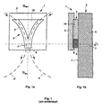
- the side face 1 according to the prior art shown schematically in Figure 1 includes a support plate 2, in which the active part 3 of the face is embedded lateral 1, ie its portion intended, during casting, to come into contact with the edges 4 cylinders 5, 5 ′ (of which only the contours have been shown in dotted lines in FIG. 1a), of liquid steel which will contain the casting space 6 of the machine and, below the level from the neck 7 where the cylinders 4, 4 ′ are as close as possible to each other, from the solidified strip. of the means (not shown) known in themselves ensure the application of the side face 1 against the edges 4 of the cylinders 5, 5 '.
- the part active 3 is, in the example shown, divided into two portions.
- Portion 8 in double arc of circle which, when the side face 1 is mounted on the machine, constitutes the area of contact with the edges 4 of the cylinders 5, 5 ′, the immediate vicinity of this contact zone and the area surrounding the neck 7, is constructed of a first refractory material.
- Its quality essential is a high hardness so that it resists friction as well as possible edges 4 of the cylinders 5, 5 'and (around the neck 7) of the strip being solidified or already solidified. It is, for example, made of SiAlON® or boron nitride. She may be consisting of a single piece or of several adjoining pieces that are integral with each other. Its lower edge 9 is located below the level of the neck 7, so as to produce a total lateral closure of the pouring space 6.
- the remaining portion 10 of the active part 3 is made of a refractory material having a high insulating power, such as silica or alumina.
- the active part 3 of the side face 1 is projecting relative to the support plate 2 with a thickness equal to at least its maximum tolerable wear during casting, by example 10 mm.
- the whole active part 3 of the side face 1 can be constituted by a single part.
- FIG. 2 which represents a lateral face 11 according to the invention mounted on the casting installation
- the elements common with those of FIG. 1 are designated by the same references.
- the lower edge 12 of the active part 3 of the lateral face 11 which ensures contact with the cylinders 5, 5 'and closes the lower part of the casting space 6 is no longer located under the neck 7, but at a distance "d" above it.
- This distance "d" can be very small, up to 1 mm, if we usually manage to regulate skin growth with great precision solidified on the edges of cylinders 5, 5 ', and if the proportion of solid matter present in the metal not yet fully solidified in this region of the casting space 6 is likely to go very quickly from 0 to 100%.
- a distance "d” of between 10 and 40 mm is suitable for the most common grades of stainless steel, cast in the form of strips 3 mm thick with 1500 mm diameter cylinders and casting speeds of around 1 m / min.
- the optimal choice of distance “d” also depends on the pressure ferrostatic reigning in the lower part of the casting space, therefore of the geometry of the casting installation and the nominal level of the surface of the liquid steel present in casting space. Good results have thus been obtained with a distance "d” of 1 to 7 mm on a machine fitted with 600 mm diameter cylinders, when casting steels low-alloy carbon and iron-silicon alloys.
- the lower edge 12 of the part active 3 of the side face 11 which faces the casting space 6 does not have a sharp angle, but a rounded 13 whose radius of curvature can, for example, be of the order of 10 to 20 mm.
- the same function can be ensured by bevelling the lower edge 12, according to a inclined plane, for example, at 45 °.
- An indicator of the effectiveness of the invention is the number of setbacks from the lateral face that we observe during casting. It was thus found that this number could be divided by three on the whole of a casting, compared to the use of descending side faces down to the neck. The improvement is even more noticeable when we consider the first minutes of casting, during which the operation of the casting machine is not always perfectly stabilized.
- the invention is applicable not only to casting between cylinders of strips of steel and other ferrous alloys, but of any other metal liable to be cast by this method.
Landscapes
- Engineering & Computer Science (AREA)
- Mechanical Engineering (AREA)
- Continuous Casting (AREA)
- Train Traffic Observation, Control, And Security (AREA)
- Rolls And Other Rotary Bodies (AREA)
- Metal Rolling (AREA)
- Moulds, Cores, Or Mandrels (AREA)
- Shearing Machines (AREA)
- Sawing (AREA)
- Arc Welding In General (AREA)
Applications Claiming Priority (2)
| Application Number | Priority Date | Filing Date | Title |
|---|---|---|---|
| FR9711351 | 1997-09-12 | ||
| FR9711351A FR2768354B1 (fr) | 1997-09-12 | 1997-09-12 | Face laterale pour l'obturation de l'espace de coulee d'une installation de coulee continue de bandes metalliques entre cylindres, et installation de coulee ainsi equipee |
Publications (2)
| Publication Number | Publication Date |
|---|---|
| EP0901851A1 EP0901851A1 (fr) | 1999-03-17 |
| EP0901851B1 true EP0901851B1 (fr) | 2003-04-09 |
Family
ID=9511009
Family Applications (1)
| Application Number | Title | Priority Date | Filing Date |
|---|---|---|---|
| EP98402164A Expired - Lifetime EP0901851B1 (fr) | 1997-09-12 | 1998-09-02 | Face laterale pour l'obturation de l'espace de coulee d'une installation de coulee continue de bandes metalliques entre cylindres, et installation de coulee ainsi equipee |
Country Status (22)
| Country | Link |
|---|---|
| EP (1) | EP0901851B1 (enExample) |
| JP (1) | JPH11151556A (enExample) |
| KR (1) | KR19990029727A (enExample) |
| CN (1) | CN1074328C (enExample) |
| AT (1) | ATE236749T1 (enExample) |
| AU (1) | AU8312298A (enExample) |
| BR (1) | BR9803422A (enExample) |
| CA (1) | CA2247538A1 (enExample) |
| CZ (1) | CZ287998A3 (enExample) |
| DE (1) | DE69813120T2 (enExample) |
| DK (1) | DK0901851T3 (enExample) |
| ES (1) | ES2196512T3 (enExample) |
| FR (1) | FR2768354B1 (enExample) |
| IN (1) | IN188785B (enExample) |
| PL (1) | PL328526A1 (enExample) |
| PT (1) | PT901851E (enExample) |
| RO (1) | RO119996B1 (enExample) |
| RU (1) | RU2208497C2 (enExample) |
| SK (1) | SK123598A3 (enExample) |
| TR (1) | TR199801783A2 (enExample) |
| TW (1) | TW504414B (enExample) |
| ZA (1) | ZA988049B (enExample) |
Families Citing this family (4)
| Publication number | Priority date | Publication date | Assignee | Title |
|---|---|---|---|---|
| JP4216340B2 (ja) * | 1996-10-18 | 2009-01-28 | ミシュラン ルシェルシュ エ テクニーク ソシエテ アノニム | セルロース材料を主成分とする液晶溶液用の水性凝固剤 |
| AT412195B (de) * | 2002-06-25 | 2004-11-25 | Voest Alpine Ind Anlagen | Verfahren zur erzeugung eines metallbandes mit einer zweiwalzengiesseinrichtung |
| FR2842130B1 (fr) * | 2002-07-12 | 2004-10-15 | Usinor | Face laterale pour installation de coulee continue de bandes metalliques entre deux cylindres |
| CN113649536B (zh) * | 2021-08-06 | 2024-12-17 | 东北大学 | 用于双辊薄带连铸的侧封板及其使用方法 |
Family Cites Families (6)
| Publication number | Priority date | Publication date | Assignee | Title |
|---|---|---|---|---|
| JPS6233047A (ja) * | 1985-08-05 | 1987-02-13 | Nisshin Steel Co Ltd | 双ドラム式連続鋳造機 |
| FR2636259B1 (fr) * | 1988-09-14 | 1994-03-11 | Irsid | Paroi laterale pour une installation de coulee continue entre parois mobiles et installation comportant cette paroi |
| FR2655577B1 (fr) * | 1989-12-07 | 1992-01-24 | Siderurgie Fse Inst Rech | Installation de coulee continue de produits metalliques minces entre deux cylindres. |
| JPH0741376B2 (ja) * | 1990-06-11 | 1995-05-10 | 新日本製鐵株式会社 | 薄帯連続鋳造方法 |
| RU2041768C1 (ru) * | 1991-12-11 | 1995-08-20 | Юзинор Сасилор С.А. | Установка для непрерывной разливки |
| JPH0749140B2 (ja) * | 1992-02-17 | 1995-05-31 | 三菱重工業株式会社 | 双ドラム式連続鋳造装置 |
-
1997
- 1997-09-12 FR FR9711351A patent/FR2768354B1/fr not_active Expired - Fee Related
-
1998
- 1998-09-02 PT PT98402164T patent/PT901851E/pt unknown
- 1998-09-02 DE DE69813120T patent/DE69813120T2/de not_active Expired - Fee Related
- 1998-09-02 EP EP98402164A patent/EP0901851B1/fr not_active Expired - Lifetime
- 1998-09-02 AT AT98402164T patent/ATE236749T1/de not_active IP Right Cessation
- 1998-09-02 DK DK98402164T patent/DK0901851T3/da active
- 1998-09-02 ES ES98402164T patent/ES2196512T3/es not_active Expired - Lifetime
- 1998-09-03 ZA ZA988049A patent/ZA988049B/xx unknown
- 1998-09-03 IN IN562BO1998 patent/IN188785B/en unknown
- 1998-09-04 AU AU83122/98A patent/AU8312298A/en not_active Abandoned
- 1998-09-09 SK SK1235-98A patent/SK123598A3/sk unknown
- 1998-09-09 CZ CZ982879A patent/CZ287998A3/cs unknown
- 1998-09-09 TR TR1998/01783A patent/TR199801783A2/xx unknown
- 1998-09-10 JP JP10256748A patent/JPH11151556A/ja not_active Withdrawn
- 1998-09-11 KR KR1019980037537A patent/KR19990029727A/ko not_active Withdrawn
- 1998-09-11 BR BR9803422-7A patent/BR9803422A/pt not_active Application Discontinuation
- 1998-09-11 PL PL98328526A patent/PL328526A1/xx unknown
- 1998-09-11 RO RO98-01379D patent/RO119996B1/ro unknown
- 1998-09-11 CN CN98119149A patent/CN1074328C/zh not_active Expired - Fee Related
- 1998-09-11 CA CA002247538A patent/CA2247538A1/fr not_active Abandoned
- 1998-09-11 RU RU98117310/02A patent/RU2208497C2/ru not_active IP Right Cessation
- 1998-09-28 TW TW087116127A patent/TW504414B/zh not_active IP Right Cessation
Also Published As
| Publication number | Publication date |
|---|---|
| PT901851E (pt) | 2003-07-31 |
| RO119996B1 (ro) | 2005-07-29 |
| CN1212914A (zh) | 1999-04-07 |
| IN188785B (enExample) | 2002-11-09 |
| TW504414B (en) | 2002-10-01 |
| JPH11151556A (ja) | 1999-06-08 |
| KR19990029727A (ko) | 1999-04-26 |
| SK123598A3 (en) | 1999-06-11 |
| TR199801783A3 (tr) | 1999-10-21 |
| CA2247538A1 (fr) | 1999-03-12 |
| DE69813120D1 (de) | 2003-05-15 |
| FR2768354A1 (fr) | 1999-03-19 |
| TR199801783A2 (xx) | 1999-10-21 |
| PL328526A1 (en) | 1999-03-15 |
| EP0901851A1 (fr) | 1999-03-17 |
| DE69813120T2 (de) | 2004-01-29 |
| ES2196512T3 (es) | 2003-12-16 |
| DK0901851T3 (da) | 2003-07-28 |
| ZA988049B (en) | 1999-03-05 |
| BR9803422A (pt) | 1999-11-03 |
| FR2768354B1 (fr) | 1999-10-22 |
| CZ287998A3 (cs) | 1999-08-11 |
| ATE236749T1 (de) | 2003-04-15 |
| AU8312298A (en) | 1999-03-25 |
| CN1074328C (zh) | 2001-11-07 |
| RU2208497C2 (ru) | 2003-07-20 |
Similar Documents
| Publication | Publication Date | Title |
|---|---|---|
| CA2173391C (fr) | Procede et dispositif de reglage du bombe des cylindres d'une installation de coulee de bandes metalliques | |
| EP0894556B1 (fr) | Face latérale d'obturation de l'espace de coulée d'une installation de coulée continue entre cylindres de bandes minces métalliques | |
| EP0901851B1 (fr) | Face laterale pour l'obturation de l'espace de coulee d'une installation de coulee continue de bandes metalliques entre cylindres, et installation de coulee ainsi equipee | |
| CA2193243C (fr) | Face laterale pour une machine de coulee en continu de tole mince | |
| EP1521650B1 (fr) | Face laterale pour installation de coulee continue de bandes metalliques entre deux cylindres | |
| EP0350345B1 (fr) | Procédé et dispositif de coulée continue de produits métalliques minces | |
| FR2833871A1 (fr) | Procede et installation de fabrication de bandes metalliques a partir de bandes coulees directement a partir de metal liquide | |
| EP0241445B1 (fr) | Dispositif et procédé pour le refroidissement d'un produit métallique coulé en continu | |
| FR2734186A1 (fr) | Procede de lubrification des parois d'une lingotiere de coulee continue des metaux et lingotiere pour sa mise en oeuvre | |
| EP0066524B1 (fr) | Procédé et dispositif de coulée continue sur roue à gorge | |
| EP0875315B1 (fr) | Installation de coulée continue de bandes métalliques entre deux cylindres | |
| FR2695580A1 (fr) | Dispositif de coulée continue entre cylindres de produits métalliques minces. | |
| EP0709151B1 (fr) | Surface de coulée d'une lingotière de coulée continue des métaux à paroi mobile | |
| CA2251007C (fr) | Procede de coulee continue des metaux et installation de coulee pour sa mise oeuvre | |
| CA2023504A1 (fr) | Procede et dispositif de coulee continue directe de produits metalliques minces | |
| EP0435729A1 (fr) | Dispositif de coulée continue de produits métalliques minces entre deux cylindres refroidis en rotation | |
| FR2785211A1 (fr) | Face laterale pour installation de coulee continue de bandes metalliques entre deux cylindres | |
| FR2757790A1 (fr) | Procede de coulee continue de bandes metalliques minces entre deux cylindres, et installation pour sa mise en oeuvre | |
| FR2557821A1 (fr) | Dispositif compensateur de l'usure d'un moule | |
| FR2723013A1 (fr) | Face laterale pour une machine de coulee en continu de tole mince | |
| WO1997014519A1 (fr) | Installation de coulee continue de filaments metalliques directement a partir de metal liquide | |
| BE904436A (fr) | Dispositif et procede pour le refroidissement d'un produit metallique coule en continu. |
Legal Events
| Date | Code | Title | Description |
|---|---|---|---|
| PUAI | Public reference made under article 153(3) epc to a published international application that has entered the european phase |
Free format text: ORIGINAL CODE: 0009012 |
|
| AK | Designated contracting states |
Kind code of ref document: A1 Designated state(s): AT BE CH CY DE DK ES FI FR GB GR IE IT LI LU NL PT SE |
|
| AX | Request for extension of the european patent |
Free format text: AL;LT;LV;MK;RO;SI |
|
| 17P | Request for examination filed |
Effective date: 19990917 |
|
| AKX | Designation fees paid |
Free format text: AT BE CH CY DE DK ES FI FR GB GR IE IT LI LU NL PT SE |
|
| 17Q | First examination report despatched |
Effective date: 20010924 |
|
| GRAH | Despatch of communication of intention to grant a patent |
Free format text: ORIGINAL CODE: EPIDOS IGRA |
|
| GRAH | Despatch of communication of intention to grant a patent |
Free format text: ORIGINAL CODE: EPIDOS IGRA |
|
| GRAA | (expected) grant |
Free format text: ORIGINAL CODE: 0009210 |
|
| AK | Designated contracting states |
Designated state(s): AT BE CH CY DE DK ES FI FR GB GR IE IT LI LU NL PT SE |
|
| REG | Reference to a national code |
Ref country code: GB Ref legal event code: FG4D Free format text: NOT ENGLISH |
|
| REG | Reference to a national code |
Ref country code: CH Ref legal event code: EP |
|
| REG | Reference to a national code |
Ref country code: IE Ref legal event code: FG4D Free format text: FRENCH |
|
| REG | Reference to a national code |
Ref country code: SE Ref legal event code: TRGR |
|
| REG | Reference to a national code |
Ref country code: GR Ref legal event code: EP Ref document number: 20030402122 Country of ref document: GR |
|
| REG | Reference to a national code |
Ref country code: DK Ref legal event code: T3 |
|
| GBT | Gb: translation of ep patent filed (gb section 77(6)(a)/1977) |
Effective date: 20030728 |
|
| PG25 | Lapsed in a contracting state [announced via postgrant information from national office to epo] |
Ref country code: LU Free format text: LAPSE BECAUSE OF NON-PAYMENT OF DUE FEES Effective date: 20030902 Ref country code: IE Free format text: LAPSE BECAUSE OF NON-PAYMENT OF DUE FEES Effective date: 20030902 Ref country code: GB Free format text: LAPSE BECAUSE OF NON-PAYMENT OF DUE FEES Effective date: 20030902 Ref country code: FI Free format text: LAPSE BECAUSE OF NON-PAYMENT OF DUE FEES Effective date: 20030902 Ref country code: CY Free format text: LAPSE BECAUSE OF FAILURE TO SUBMIT A TRANSLATION OF THE DESCRIPTION OR TO PAY THE FEE WITHIN THE PRESCRIBED TIME-LIMIT Effective date: 20030902 Ref country code: AT Free format text: LAPSE BECAUSE OF NON-PAYMENT OF DUE FEES Effective date: 20030902 |
|
| PG25 | Lapsed in a contracting state [announced via postgrant information from national office to epo] |
Ref country code: SE Free format text: LAPSE BECAUSE OF NON-PAYMENT OF DUE FEES Effective date: 20030903 Ref country code: ES Free format text: LAPSE BECAUSE OF NON-PAYMENT OF DUE FEES Effective date: 20030903 |
|
| PG25 | Lapsed in a contracting state [announced via postgrant information from national office to epo] |
Ref country code: LI Free format text: LAPSE BECAUSE OF NON-PAYMENT OF DUE FEES Effective date: 20030930 Ref country code: DK Free format text: LAPSE BECAUSE OF NON-PAYMENT OF DUE FEES Effective date: 20030930 Ref country code: CH Free format text: LAPSE BECAUSE OF NON-PAYMENT OF DUE FEES Effective date: 20030930 Ref country code: BE Free format text: LAPSE BECAUSE OF NON-PAYMENT OF DUE FEES Effective date: 20030930 |
|
| REG | Reference to a national code |
Ref country code: ES Ref legal event code: FG2A Ref document number: 2196512 Country of ref document: ES Kind code of ref document: T3 |
|
| PLBE | No opposition filed within time limit |
Free format text: ORIGINAL CODE: 0009261 |
|
| STAA | Information on the status of an ep patent application or granted ep patent |
Free format text: STATUS: NO OPPOSITION FILED WITHIN TIME LIMIT |
|
| 26N | No opposition filed |
Effective date: 20040112 |
|
| BERE | Be: lapsed |
Owner name: *THYSSEN STAHL A.G. Effective date: 20030930 Owner name: *USINOR Effective date: 20030930 |
|
| PG25 | Lapsed in a contracting state [announced via postgrant information from national office to epo] |
Ref country code: NL Free format text: LAPSE BECAUSE OF NON-PAYMENT OF DUE FEES Effective date: 20040401 Ref country code: DE Free format text: LAPSE BECAUSE OF NON-PAYMENT OF DUE FEES Effective date: 20040401 |
|
| GBPC | Gb: european patent ceased through non-payment of renewal fee | ||
| EUG | Se: european patent has lapsed | ||
| REG | Reference to a national code |
Ref country code: DK Ref legal event code: EBP |
|
| REG | Reference to a national code |
Ref country code: CH Ref legal event code: PL |
|
| PG25 | Lapsed in a contracting state [announced via postgrant information from national office to epo] |
Ref country code: FR Free format text: LAPSE BECAUSE OF NON-PAYMENT OF DUE FEES Effective date: 20040528 |
|
| NLV4 | Nl: lapsed or anulled due to non-payment of the annual fee |
Effective date: 20040401 |
|
| REG | Reference to a national code |
Ref country code: IE Ref legal event code: MM4A |
|
| REG | Reference to a national code |
Ref country code: FR Ref legal event code: ST |
|
| PG25 | Lapsed in a contracting state [announced via postgrant information from national office to epo] |
Ref country code: PT Free format text: LAPSE BECAUSE OF NON-PAYMENT OF DUE FEES Effective date: 20041015 |
|
| REG | Reference to a national code |
Ref country code: ES Ref legal event code: FD2A Effective date: 20030903 |
|
| PG25 | Lapsed in a contracting state [announced via postgrant information from national office to epo] |
Ref country code: GR Free format text: LAPSE BECAUSE OF NON-PAYMENT OF DUE FEES Effective date: 20050405 |
|
| PG25 | Lapsed in a contracting state [announced via postgrant information from national office to epo] |
Ref country code: IT Free format text: LAPSE BECAUSE OF NON-PAYMENT OF DUE FEES Effective date: 20050902 |
|
| PG25 | Lapsed in a contracting state [announced via postgrant information from national office to epo] |
Ref country code: GR Free format text: LAPSE BECAUSE OF NON-PAYMENT OF DUE FEES Effective date: 20030409 |
|
| PG25 | Lapsed in a contracting state [announced via postgrant information from national office to epo] |
Ref country code: PT Free format text: LAPSE BECAUSE OF NON-PAYMENT OF DUE FEES Effective date: 20030902 |