EP0900989A2 - Heizkörperventil - Google Patents
Heizkörperventil Download PDFInfo
- Publication number
- EP0900989A2 EP0900989A2 EP98202921A EP98202921A EP0900989A2 EP 0900989 A2 EP0900989 A2 EP 0900989A2 EP 98202921 A EP98202921 A EP 98202921A EP 98202921 A EP98202921 A EP 98202921A EP 0900989 A2 EP0900989 A2 EP 0900989A2
- Authority
- EP
- European Patent Office
- Prior art keywords
- protective cap
- radiator valve
- radiator
- valve according
- housing
- Prior art date
- Legal status (The legal status is an assumption and is not a legal conclusion. Google has not performed a legal analysis and makes no representation as to the accuracy of the status listed.)
- Withdrawn
Links
- 230000001681 protective effect Effects 0.000 claims abstract description 77
- 230000002093 peripheral effect Effects 0.000 abstract 1
- 238000004519 manufacturing process Methods 0.000 description 8
- 238000010276 construction Methods 0.000 description 2
- 230000002787 reinforcement Effects 0.000 description 2
- 238000010438 heat treatment Methods 0.000 description 1
- 238000009434 installation Methods 0.000 description 1
- 239000007788 liquid Substances 0.000 description 1
- 238000000034 method Methods 0.000 description 1
- XLYOFNOQVPJJNP-UHFFFAOYSA-N water Substances O XLYOFNOQVPJJNP-UHFFFAOYSA-N 0.000 description 1
Images

Classifications
-
- F—MECHANICAL ENGINEERING; LIGHTING; HEATING; WEAPONS; BLASTING
- F24—HEATING; RANGES; VENTILATING
- F24D—DOMESTIC- OR SPACE-HEATING SYSTEMS, e.g. CENTRAL HEATING SYSTEMS; DOMESTIC HOT-WATER SUPPLY SYSTEMS; ELEMENTS OR COMPONENTS THEREFOR
- F24D19/00—Details
- F24D19/0002—Means for connecting central heating radiators to circulation pipes
Definitions
- the invention relates to a radiator valve a housing that has a screw thread and a Has torque application surface arrangement on the circumference, with an actuator and with a protective cap, which is attached to the housing and the actuator covers.
- the radiator valve is screwed in a radiator or screwed onto it. Of the Radiator is then together with the screwed valve transported to the construction site and assembled there. So that the actuator is not damaged, a protective cap is placed on the actuator covers. Then the protective cap will come out later exchanged for an actuator, for example against a thermostatic head.
- the protective cap is very useful and useful. But it complicates the assembly of the radiators because after installing the radiator valve the additional one Step of assembling the protective cap required is.
- the invention has for its object the manufacture of radiators to simplify.
- This task is the beginning of a radiator valve mentioned type in that the torque application surface arrangement related to the screwing direction protrudes radially over the protective cap.
- the screwing direction is not the direction of rotation, but the axial direction along which the valve is screwed into the radiator.
- the screwing tool required for this can namely run over the protective cap and the torque application surface arrangement reach without being hindered by the protective cap. So far this has not been possible. So far you had the protective caps always dimensioned as large as possible, so that they are radial over the torque application surface arrangement survived.
- This training was chosen so the fitter both during assembly and during removal the protective cap with as few tools as possible got along. In the procedure according to the invention, it is although also necessary to mount a protective cap. However, this manufacturing step can already be carried out during Assemble the radiator valve.
- the protective cap radially at every point in the circumferential direction within the torque application surface arrangement lies. So you can screw in the radiator valve use a tool in the radiator, this on the one hand on the torque application surface arrangement can fully concern and on the other hand in everyone Rotary position can be placed. You don't have to pay more attention that the screw-in tool has a certain Alignment with the radiator valve in which it has can be passed over the protective cap.
- the protective cap preferably acts on the actuating device, if it is attached to the housing.
- the setting of the actuator with the help of the protective cap known per se. This setting has been made so far always only with valve installed, see above that the actual degree of opening of the valve more or less based on chance.
- the protective cap is preferably screwed on. In order to a relatively precise setting can be realized.
- the actuating device is preferably a pin and the protective cap as a cup in the area of Pencil reinforced base.
- the protective cap can be dimensioned relatively thin-walled on the one hand, so that it remains inexpensive.
- the protective cap due to the reinforced bottom in able to pin the actuator in sufficient Apply dimensions without the protective cap itself is noticeably deformed. In this way a relatively precise adjustability can be achieved.
- the protective cap essentially has one cylindrical outer shape. It thus serves at the same time as a guide for a screw-in tool, for example a socket wrench on the torque application surface arrangement is put on. That simplifies the installation of the radiator valve in the radiator.
- An adjustment device is also advantageous provided and the protective cap is an adjustment tool educated.
- the adjustment device which in itself is known, a certain basic attitude of the radiator valve. This basic setting in many cases has to be done on site when the radiator is installed in the building. If now the protective cap at the same time as an adjustment tool trained, you can do the basic setting immediately after removing the protective cap Has. You even have the adjustment tool at the same time at hand.
- a secondary torque application surface arrangement has a corresponding Arrangement adjusted on the adjusting device is.
- the adjustment device is in many cases as Ring or the like that is made to rotate can have a corresponding shape. This shape serves as a secondary torque application surface arrangement and can, for example, by parallel, opposite surface sections formed be, by one or more protrusions, by a polygon, through a multiple wedge arrangement or through recesses. If the protective cap is now appropriate Forming has, then you can Simply put on the protective cap and the basic setting with the help of the adjusting device.
- the protective cap preferably has in its end face at least one opening, which is arranged off-center is. Because the opening is arranged off-center ensures that there is an area in the middle remains that press on the actuator can, especially if this is designed as a pen is. Conversely, the opening can serve the Let the pen pass through when using the adjuster want to operate.
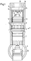
- a screwing tool is used for screwing in 5 used that in the manner of a socket wrench on the Radiator valve 1 is plugged in and engaged comes with a torque application surface arrangement 6, which is formed on the housing 3.
- This is in the present Case a tooth structure with twelve external teeth 7 and corresponding tooth flanks on which the screwing tool 5 is plugged on. Accordingly, that Screw-in tool on its radial inside corresponding Internal teeth 8 on.
- the housing 3 can also be composed of several parts.
- An actuator is also in the radiator valve 1 9 provided in a manner known per se serves to actuate a valve element 10.
- the actuator 9 is designed here as a pin. It is in the axial direction (based on the screw-in direction of the external thread 2). The pencil is guided through a stuffing box and should therefore be protected from side loads.
- a protective cap 11 is screwed onto the housing 3.
- the protective cap 11 has an internal thread 12 and the housing 3 a further external thread 13 on.
- the protective cap has the shape of a cup, i.e. of a hollow cylinder closed on one side.
- the inside diameter the protective cap 11 is chosen so that the Protective cap 11 screwed onto the part of the housing 3 can be the actuator 9th is adjacent.
- the outer diameter of the protective cap 11 is selected so that the entire protective cap 11 in the radial direction (related to the screwing in direction as axial direction) within the torque application surface arrangement 6 lies. Accordingly, the screwing tool 5 over the screwed-on protective cap 11 are guided and with the torque application surface arrangement 6 come into engagement.
- the protective cap 11 even serves advantageously as a guide for the screw-in tool 5. Accordingly the radiator valve 1 before it is installed in Radiator 4 provided with the protective cap 11. This is used in the manufacture of the radiator valve 1 screwed on, so that protective cap 11 and radiator valve 1 as a jointly manageable unit also outside of the radiator 4 are present.
- the protective cap has a reinforcement in its base 14 15 on. With this reinforcement 15 presses Protective cap screwed onto the pin the actuator 9. This becomes the actuator 9 actuated and the radiator valve 1 receives a predetermined degree of opening. Because this degree of opening already in the manufacture of the radiator valve 1 is set, it can be checked. You can do this with relatively little effort make sure that radiator 4, which with such Radiator valves 1 are provided, a predetermined Have heating capacity, i.e. at a given A predetermined amount of water flows through the pressure can be. This is particularly advantageous if such equipped radiators are installed in new buildings where they should heat, the thermostats but have not yet been put on.
- the bottom 14 has two openings 16 which are arranged off-center.
- Fig. 2 shows that screwed into the radiator 4 Radiator valve 1 with protective cap 11 removed Protective cap 11 is now turned over and is used as an adjustment tool used for an adjusting device 17.
- the Setting device 17 is used to set a Basic setting of the radiator valve 1. This basic setting usually has to be done on site. If you have removed the protective cap, then you have this screwing tool is immediately available.
- Fig. 3 shows the protective cap 11 as an adjusting tool with a section that is 90 ° compared to that of FIG. 2 is rotated. It can be seen that the bottom 14, the Protective cap 11 on its outside, i.e. on the in installed condition away from the housing 3, has a secondary torque application surface arrangement 18. This is due to the outer shape of the adjustment device 17 adjusted.
- the opening 16 serves to the setting device 9 when setting the Let basic setting pass through, so here no additional forces are necessary to the pen the actuator 9 or otherwise to operate.
- FIG. 4a A first embodiment is shown in Fig. 4a.
- the setting device has 17 the shape of a hexagon.
- the radiator valve 1 is, as I said, still in the frame provided with the protective cap 11 during its manufacture. In order to it can coexist with a certain capacity setting be delivered.
- the actuator 9 is then not only in the transport of the complete radiator from manufacturing the radiator protected to the assembly site, but also at the Screw the radiator valve into the radiator. Screwing in is possible because of the screwing tool can be passed over the protective cap 11 and accordingly not with the protective cap 11 in Conflict comes. This is especially true if you makes sure that the protective cap 11 in the circumferential direction over all completely within the torque application surface arrangement 6 remains.
Landscapes
- Engineering & Computer Science (AREA)
- Physics & Mathematics (AREA)
- Thermal Sciences (AREA)
- Chemical & Material Sciences (AREA)
- Combustion & Propulsion (AREA)
- Mechanical Engineering (AREA)
- General Engineering & Computer Science (AREA)
- Temperature-Responsive Valves (AREA)
- Valve Housings (AREA)
Abstract
Description
- Fig. 1
- einen schematischen Querschnitt durch ein Heizkörperventil mit aufgesetzter Schutzkappe und Montagewerkzeug,
- Fig. 2
- das Heizkörperventil mit Schutzkappe als Einstellwerkzeug,
- Fig. 3
- einen Schnitt senkrecht zum Schnitt nach Fig. 2 und
- Fig. 4
- verschiedene Möglichkeiten für eine Schnittansicht nach Linie IV-IV nach Fig. 3.
Claims (9)
- Heizkörperventil mit einem Gehäuse, das ein Einschraubgewinde und eine Drehmomentangriffsflächenanordnung am Umfang aufweist, mit einer Betätigungseinrichtung und mit einer Schutzkappe, die am Gehäuse befestigt ist und die Betätigungseinrichtung abdeckt, dadurch gekennzeichnet, daß die Drehmomentangriffsflächenanordnung (6) bezogen auf die Einschraubrichtung radial über die Schutzkappe (11) vorsteht.
- Heizkörperventil nach Anspruch 1, dadurch gekennzeichnet, daß die Schutzkappe (11) an jeder Stelle in Umfangsrichtung radial innerhalb der Drehmomentangriffsflächenanordnung (6) liegt.
- Heizkörperventil nach Anspruch 1 oder 2, dadurch gekennzeichnet, daß die Schutzkappe (11) die Betätigungseinrichtung (9) beaufschlagt, wenn sie am Gehäuse (3) befestigt ist.
- Heizkörperventil nach Anspruch 3, dadurch gekennzeichnet, daß die Schutzkappe (11) aufgeschraubt ist.
- Heizkörperventil nach Anspruch 3 oder 4, dadurch gekennzeichnet, daß die Betätigungseinrichtung (9) als Stift und die Schutzkappe (11) als Becher mit im Bereich des Stifts verstärktem Boden (14) ausgebildet ist.
- Heizkörperventil nach einem der Ansprüche 1 bis 5, dadurch gekennzeichnet, daß die Schutzkappe (11) eine im wesentlichen zylindrische Außenform aufweist.
- Heizkörperventil nach einem der Ansprüche 1 bis 6, dadurch gekennzeichnet, daß zusätzlich eine Einstellvorrichtung (17) vorgesehen ist und die Schutzkappe (11) als Einstellwerkzeug ausgebildet ist.
- Heizkörperventil nach Anspruch 7, dadurch gekennzeichnet, daß die Schutzkappe (11) auf ihrer Außenseite, insbesondere auf ihrer dem Gehäuse (3) abgewandten Stirnseite, eine Sekundärdrehmomentangriffsflächenanordnung (18) aufweist, die an eine entsprechende Anordnung an der Einstellvorrichtung (17) angepaßt ist.
- Heizkörperventil nach Anspruch 7 oder 8, dadurch gekennzeichnet, daß die Schutzkappe (11) in ihrer Stirnseite mindestens eine Öffnung (16) aufweist, die außermittig angeordnet ist.
Applications Claiming Priority (2)
| Application Number | Priority Date | Filing Date | Title |
|---|---|---|---|
| DE19739109 | 1997-09-06 | ||
| DE19739109A DE19739109C2 (de) | 1997-09-06 | 1997-09-06 | Heizkörperventil |
Publications (2)
| Publication Number | Publication Date |
|---|---|
| EP0900989A2 true EP0900989A2 (de) | 1999-03-10 |
| EP0900989A3 EP0900989A3 (de) | 2001-03-28 |
Family
ID=7841468
Family Applications (1)
| Application Number | Title | Priority Date | Filing Date |
|---|---|---|---|
| EP98202921A Withdrawn EP0900989A3 (de) | 1997-09-06 | 1998-09-02 | Heizkörperventil |
Country Status (2)
| Country | Link |
|---|---|
| EP (1) | EP0900989A3 (de) |
| DE (1) | DE19739109C2 (de) |
Cited By (2)
| Publication number | Priority date | Publication date | Assignee | Title |
|---|---|---|---|---|
| EP1517098A1 (de) * | 2003-09-17 | 2005-03-23 | KERMI GmbH | Heizkörperventil |
| EP2746889A1 (de) * | 2012-12-22 | 2014-06-25 | Danfoss A/S | Verfahren und Einstellwerkzeug zum Einstellen einer Voreinstellung eines Ventils, insbesondere eines Wärmetauscherventils |
Family Cites Families (1)
| Publication number | Priority date | Publication date | Assignee | Title |
|---|---|---|---|---|
| DE9415298U1 (de) * | 1994-09-21 | 1994-12-01 | Schlösser GmbH Armaturenfabrik - Metallgießerei, 57462 Olpe | Voreinstellbarer Ventileinsatz für Heizkörperthermostate |
-
1997
- 1997-09-06 DE DE19739109A patent/DE19739109C2/de not_active Expired - Fee Related
-
1998
- 1998-09-02 EP EP98202921A patent/EP0900989A3/de not_active Withdrawn
Non-Patent Citations (1)
| Title |
|---|
| None |
Cited By (4)
| Publication number | Priority date | Publication date | Assignee | Title |
|---|---|---|---|---|
| EP1517098A1 (de) * | 2003-09-17 | 2005-03-23 | KERMI GmbH | Heizkörperventil |
| EP2746889A1 (de) * | 2012-12-22 | 2014-06-25 | Danfoss A/S | Verfahren und Einstellwerkzeug zum Einstellen einer Voreinstellung eines Ventils, insbesondere eines Wärmetauscherventils |
| WO2014095177A1 (en) * | 2012-12-22 | 2014-06-26 | Danfoss A/S | A method and an adjusting tool for adjusting a presetting of a valve, in particular a heat exchanger valve |
| CN104854526A (zh) * | 2012-12-22 | 2015-08-19 | 丹佛斯公司 | 用于调整阀、尤其是热交换器阀的预设的方法和调整工具 |
Also Published As
| Publication number | Publication date |
|---|---|
| EP0900989A3 (de) | 2001-03-28 |
| DE19739109C2 (de) | 2000-04-20 |
| DE19739109A1 (de) | 1999-03-25 |
Similar Documents
| Publication | Publication Date | Title |
|---|---|---|
| EP0959978B1 (de) | Filter | |
| CH669023A5 (de) | Kupplung fuer eine druckgasleitung. | |
| EP1965119B1 (de) | Verteilerrohr und Warmwasserverteiler für eine Fussbodenheizung sowie Verfahren zur Herstellung des Verteilerrohrs | |
| DE3604194A1 (de) | Stopfen fuer waermetauscherrohre oder -leitungen | |
| DE3544130A1 (de) | Greifer fuer handhabungsgeraete | |
| EP2530365B2 (de) | Ventileinsatz für eine Sanitärarmatur | |
| DE2812927A1 (de) | Zwischenplatte fuer ein hydraulisches verkettungssystem | |
| DE2113008A1 (de) | Zylinderschloss | |
| DE10349925A1 (de) | Einbauventil für einen Heizkörper, insbesondere Gliederheizkörper | |
| EP2102509B1 (de) | Zuganker und damit zusammengespannte modulanordnung | |
| DE3925293C3 (de) | Vorrichtung zum lösbaren Verbinden einer Druckmittelleitung an einem Druckmittelanschluß | |
| EP0900989A2 (de) | Heizkörperventil | |
| DE102005060120B4 (de) | Heizkörper-Einbauventil | |
| DE29804345U1 (de) | Kugelgelenk mit Schnappverriegelung | |
| DE10007527C2 (de) | Dichtpackung zum Hindurchführen von Leitungen durch eine Wand | |
| CH671260A5 (de) | ||
| EP1102142A2 (de) | Ventil, insbesondere Thermostatventil für Heizungsanlagen | |
| EP3537017A1 (de) | Ventil | |
| DE102004004636B4 (de) | Thermostatventilaufsatz-Gehäuse | |
| DE1550067B1 (de) | Gehaeuseabdeckung fuer einen Schieber | |
| WO2020169309A1 (de) | Kugelgewindetrieb mit verdrehsicherung | |
| DE10108520B4 (de) | Heizungsventilaufsatz | |
| DE102009031442B4 (de) | Betätigungsaufsatz zur Betätigung eines Heizungsventils | |
| EP2226541B1 (de) | Betätigungsanordnung für Sanitärarmaturen | |
| EP1982090A1 (de) | Scheibenbremse, insbesondere für nutzfahrzeuge |
Legal Events
| Date | Code | Title | Description |
|---|---|---|---|
| PUAI | Public reference made under article 153(3) epc to a published international application that has entered the european phase |
Free format text: ORIGINAL CODE: 0009012 |
|
| AK | Designated contracting states |
Kind code of ref document: A2 Designated state(s): AT DE FR GB IT SE |
|
| AX | Request for extension of the european patent |
Free format text: AL;LT;LV;MK;RO;SI |
|
| PUAL | Search report despatched |
Free format text: ORIGINAL CODE: 0009013 |
|
| AK | Designated contracting states |
Kind code of ref document: A3 Designated state(s): AT BE CH CY DE DK ES FI FR GB GR IE IT LI LU MC NL PT SE |
|
| AX | Request for extension of the european patent |
Free format text: AL;LT;LV;MK;RO;SI |
|
| 17P | Request for examination filed |
Effective date: 20010412 |
|
| AKX | Designation fees paid |
Free format text: AT DE FR GB IT SE |
|
| STAA | Information on the status of an ep patent application or granted ep patent |
Free format text: STATUS: THE APPLICATION IS DEEMED TO BE WITHDRAWN |
|
| 18D | Application deemed to be withdrawn |
Effective date: 20020403 |