EP0900985B1 - Method for cooling of an oven door and oven with cooling system - Google Patents
Method for cooling of an oven door and oven with cooling system Download PDFInfo
- Publication number
- EP0900985B1 EP0900985B1 EP98116296A EP98116296A EP0900985B1 EP 0900985 B1 EP0900985 B1 EP 0900985B1 EP 98116296 A EP98116296 A EP 98116296A EP 98116296 A EP98116296 A EP 98116296A EP 0900985 B1 EP0900985 B1 EP 0900985B1
- Authority
- EP
- European Patent Office
- Prior art keywords
- door
- panel
- cooling
- cooling air
- muffle
- Prior art date
- Legal status (The legal status is an assumption and is not a legal conclusion. Google has not performed a legal analysis and makes no representation as to the accuracy of the status listed.)
- Expired - Lifetime
Links
Images


Classifications
-
- F—MECHANICAL ENGINEERING; LIGHTING; HEATING; WEAPONS; BLASTING
- F24—HEATING; RANGES; VENTILATING
- F24C—DOMESTIC STOVES OR RANGES ; DETAILS OF DOMESTIC STOVES OR RANGES, OF GENERAL APPLICATION
- F24C15/00—Details
- F24C15/006—Arrangements for circulation of cooling air
-
- F—MECHANICAL ENGINEERING; LIGHTING; HEATING; WEAPONS; BLASTING
- F24—HEATING; RANGES; VENTILATING
- F24C—DOMESTIC STOVES OR RANGES ; DETAILS OF DOMESTIC STOVES OR RANGES, OF GENERAL APPLICATION
- F24C15/00—Details
- F24C15/02—Doors specially adapted for stoves or ranges
- F24C15/04—Doors specially adapted for stoves or ranges with transparent panels
Definitions
- the invention relates to a method for cooling a oven door and a oven.
- pyrolytic Self-cleaning pyrolysis of the oven muffle known which heats the interior of the muffle to temperatures of up to 500 ° C and the cooking residues in easily removable Ashes are converted. Because of the high temperatures special measures are required for pyrolytic self-cleaning be taken to the oven door (oven door) at the front that people can come into contact with even during pyrolysis at a critical temperature to keep.
- the oven door usually has an inner pane facing the muffle and an outer pane applied by the muffle each made of glass. To even during a pyrolytic Self-cleaning sufficiently low temperatures at the To ensure the outer pane are generally in the Door between the inner pane and the outer pane one or several additional washers for thermal insulation used and the oven muffle outside and Door are forced by convection of a cooling fan cooled.
- EP 0 583 180 A1 discloses a household cooking oven with an oven muffle and with a door for closing the loading opening of the oven muffle.
- the door has an inner pane, an intermediate pane and an outer pane, which are held in a door frame.
- a cooling fan is arranged above the oven muffle, which sucks in fresh cooling air from an outside space in a suction area under the oven muffle and guides it around the oven muffle and blows it back into the outside space in a blow-out area above the door.
- the door Above the suction area, the door has air inlet openings in the frame floor and air outlet openings below the blow-out area.
- US-A-3 561 423 is a door structure for one described self-cleaning oven that allows air with natural convection one after the other from outside, from the bottom up between an outer panel and one Intermediate plate and from top to bottom between the Guide intermediate plate and an inner plate and finally, as desired, preheated into the oven muffle.
- FR-A-2655132 shows a device for cooling a Oven door between an inner pane and an intermediate pane has a first channel through which a Fan-generated air flow pushed down from the top to exit into the outside space, and between the washer and an outer washer one of the first Channel separated second channel in the air in one lower area from outside enters to under Injector action of a fan-generated air flow in one exit the upper area again into the outside space.
- the invention is based on the object, a muffle door of the aforementioned type, especially in pyrolysis operation, to cool efficiently.
- the invention is based on the consideration of at least one Washer from an air flow in one handy flow around the closed path so that the Air flow is not divided into two parallel air flows but an air flow first at one Flows along side of the washer and then on the side facing away from this side at least flows approximately in the opposite direction.
- the door can be cooled with high efficiency and over a large pressure range (performance of the cooling device) an even airflow can be generated.
- this is a first advantageous embodiment characterized in that the cooling air is initially by the between the inner pane and the washer inner space and then through the between the intermediate disc and the outer disc formed outer Intermediate space is directed.
- Cooling air first through the outer space between the washer and the outer washer and then through the inner space between the inner pane and the washer is passed.
- the cooling can now only be provided for the door. It can also use other parts of the oven from the cooling air can be detected.
- the cooling air after flowing around the Guide the washer out of the door and around at least part of the oven muffle passed to also to cool the area around the oven muffle. Then will the cooling air is preferably in one or more blow-out areas headed back into the outside space. At least one Blow-out area is then in an advantageous embodiment in an upper area of the door or above the door arranged.
- the cooling air from the outside in one lower area of the door passed into the door to the. in general to use particularly cool air on the ground.
- the cooling air can also flow around the washer led out of the door in a lower area of the door become.
- a preferred application is door cooling according to Invention in the pyrolytic self-cleaning of the muffle, at which particularly high temperatures occur.
- the intermediate disk protrudes below in the intake area than the inner pane.
- the intermediate disk protrudes below in the intake area than the inner pane.
- the outer pane, the inner pane and each washer are each at least in a preferred embodiment partly optically transparent to give an insight into to allow the muffle interior.
- the cooling device generally comprises at least one Cooling fan, which is located either outside the door and with the outlet openings of the door via at least one Flow channel is connected, or in the door itself can be arranged.
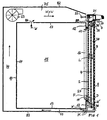
- FIG. 1 is a household oven in a side Section shown with a muffle 10, a door 9 to close a loading opening 16 of the furnace muffle 10 and a housing 83. Above the furnace muffle 10 a cooling fan (cooling device) 23 is arranged. In one A blow-out area 37 is provided in the upper area of the door 9 and a suction area 36 is formed below the door 9.
- connection 84 provided via the vapors W from the muffle interior 15 is discharged into the air duct 75 and together with the cooling air K from the blow-out area 37 is blown out.
- the vapor W can also be diverted to another location and are not supplied to the cooling air K, for example with a built-in cooker via the associated built-in hob.
- the door 9 has an inner pane 2 and an outer pane 3 and one between the inner pane 2 and the outer pane 3 arranged washer 4.
- the intermediate disc 4 and the outer disc 3 are preferably parallel spaced from each other and can also be arranged at an angle to each other his. As a result, there are between the inner pane 2 and the intermediate pane 4 an inner space 24 and between the Outer pane 3 and the washer 4 an outer space 34 formed.
- an intermediate washer 4 can also consist of several panes Intermediate washers are provided.
- an air guide 98 is provided in the door 9, said Spaces 24 and 34 from the air duct 75 and the blow-out area 37 for the cooling air K and Wrasen W separates.
- This air guide 98 can in particular be an air baffle that lies tightly against the inner pane 2.
- a connection area 38 is formed, via which the inner space 24 and the outer space 34 the door 9 are in flow connection.
- Air outlet area (air gap) 35 formed over which the Connection area 38 is connected to the outside space.
- This Air outlet area 35 can in particular between approximately 2 mm and about 6 mm high.
- the air baffle 98 is preferably slightly advanced in front of the outer pane 3 a flow dynamic influencing of the door interior in the air outlet area 35 emerging air through the exiting above the air guide body 98 in the blow-out area 37 To prevent cooling air K at least largely. This can still be supported by using the blowout area or areas 37 for the cooling air K over the side of the door arranges offset to the air outlet area 35.
- the inner space 24 and the outer space 34 are each closed at the side and stand on their respective lower end with the suction region 36 in flow communication.
- the outer intermediate space 34 opens out closer to the suction area 36 than the inner space 24. This is achieved by facing the inner pane 2 the washer 4 is displaced upwards, for example around 15 mm to 30 mm and preferably between about 20 mm and 25 mm.
- the outer pane 3 can also do something be longer down than the washer 4, for example by a few millimeters. Through this Measures is the intake pressure, which is with the cooling fan running 23 acts in the suction area 36, at the lower mouth of the inner space 24 is not as large as at the lower Mouth of the outer space 34.
- the domestic oven has a pyrolytic self-cleaning function has, is on a door handle 21 of the door 9 a locking bolt 22 for locking the door 9 during of the pyrolysis operation provided in a, not shown Lock engages.
- the inner pane 2 and / or the intermediate disc 4 with a heat radiation reflecting Layer, for example one Metal oxide to be coated to the heat radiation in the Reflect back muffle interior 19.
- the Inner pane 2, intermediate pane 4 and the outer pane 3 generally consist of at least partially transparent (optically transparent) material, for example Glass or a glass ceramic, so that in the door 9 Viewing window is formed in the muffle interior 15, and are preferably rectangular in shape, with the inner pane 2 generally smaller than the outer pane 3 is ..
- the two Carrier elements 5 and 6 each have a columnar shape Middle part 51 or 61 and two laterally from the middle part 51 and 61 protruding flange edges 50 and 60 on and can be formed in particular from U-shaped profiled sheet metal his.
- the flange edges 50 and 60 are the two Carrier elements 5 and 6 each glued to the outer pane 3. Due to the comparatively large adhesive surface Forces from the support elements 5 and 6 evenly on the Transfer outer pane 3 so that the outer pane shatters 3 due to thermal or mechanical stresses is practically avoided.
- the adhesive bond ensures moreover a gentle connection of the carrier elements 5 and 6 with the.
- Outer pane 3 during manufacture. However, it can also a screw connection, a snap connection or another connection of the support elements 5 and 6 with the Outer pane 3 may be provided.
- In an upper area of the A door handle 21 is attached to the carrier elements 5 and 6.
- the inner pane 2 On the storage surfaces 52 facing away from the outer pane 3 and 62 of the middle parts 51 and 61 of the two carrier elements 5 and 6, the inner pane 2 is in the installed state on.
- the two holding elements 7 and 8 are each designed as angled rails, which run over the entire height of the inner pane 2.
- the inner pane 2 is between the two holding elements 7 and 8 and the one on the opposite Side of the inner pane 2 lying support surfaces 52 or 62 of the support elements 5 and 6 held.
- the two carrier elements 5 and 6 in their lower areas each have a receiving part 25 and 26 for the inner pane 2 attached, especially screwed, snapped or tense.
- the two receiving parts 25 and 26 exist preferably made of a plastic.
- Corners of the inner pane 2 is in a corresponding, angular area of the associated receiving part 25 or 26 fitted, the inner pane 2 on each corner is supported at the bottom and on a vertical stop and a horizontal stop and thus to the inside, i.e. towards the oven muffle, and down in front of the Falling out is secured.
- the angular holding elements 7 and 8 are on the outer side surfaces of the carrier elements 5 and 6 each with the associated support elements 5 and 6 respectively in each case a locking switch 70 or 80 releasably connected.
- Each interlock switch 70 and 80 has one Operating handle 71 or 81 and is with this operating handle 71 and 81 each axially (linearly) displaceable. In a first end position of the operating handle 71 or 81 the associated locking switch 70 or 80 is locked and unlocked in the other end position. In the locked position of the lock switch 70 or 80 is the associated holding element 7 or 8 below a predetermined Contact pressure on the inner pane 2 and holds the Inner pane 2 fixed. The inner pane 2 should, however enough space to compensate for thermal expansion and avoiding thermal stresses are available. In the unlocked state of the locking switch 70 or 80 is the holding element 7 or 8 from the inner pane 2 detachable (removable).
- Receiving parts 25 and 26 is an opening 27 and 28 provided for performing components for movement the door in particular door hinge or baking cart pull-out parts, which then into the internally hollow support element 5 or 6th inserted and locked there.
- the washer 4 is between the outer pane 3 and the inner pane 2 and between the two carrier elements 5 and 6 inserted into the door and preferably has inserted or sprayed on frame elements (frame parts, edge parts) 93 and 94 preferably made of plastic.
- frame elements 93 and 94 On the frame elements 93 and 94 are spacers 10, 12, 14, 16 and 18 for maintaining a distance between the washer 4 and the inner pane 2 on the one hand and on the opposite side spacers 11, 13, 15, 17 and 19 for maintaining a distance between the washer 4 and the outer pane 3 are provided.
- the spacers 12 to 17 on the frame members 93 and 94 can especially a convexly curved (round), preferably have a semicircular shape.
- the extreme in height Spacers 10 and 11 and 18 and 19 are for example paddle-shaped. With the spacers 18 and 19 of the The intermediate plate 4 rests on frame elements 93 and 94 a corresponding contact surface of the receiving part 25 and. is thereby supported downwards.
- the intermediate pane can now also be used 4, especially for cleaning purposes with the frame elements 93 and 94 easily removed from the door be, for example by slightly lifting and then pulling forward.
- FIG 1 flows around Cooling air K the washer 4 first inside and then Outside.
- FIGS. 3 and 4 each show one Embodiment in which the cooling air is the washer 4 flow around outside and then inside, the sense of flow is just turned over.
- connection area 38 fluidically in. Connection.
- This connection area 38 is up and laterally also completed by the door frame 90.
- the panes 2 to 4 are framed in the door frame 90. Below are the two spaces 24 and 34 through the Washer 4 separated from each other.
- At least one suction opening is located in the door frame 90 at the bottom (Air inlet opening) 31, through the cooling air K from an outside space get into the outer space 34 of the door 9 can, and at least one outlet opening (air outlet opening) 32 through which through the door.9 and around the washer 4 flowed cooling air designated K ' the inner space 24 can emerge from the door 9, educated.
- the at least one suction opening 31 is shown in FIG Embodiment arranged below. It can but also all or part of the suction openings on the Side of the door frame 90 and / or further up in the door frame Be 90.
- the suction opening (s) 31 and the exhaust opening (s) 32 can also again, as in the embodiment 1 and 2, through the downwardly open ends of the spaces 34 and 23 are formed in one after door open at the bottom 9. Furthermore, the suction opening 31 and the blow-out opening 32 through a flow separating body 33, for example, a bent sheet, fluidically separated from each other.
- Cooling fan 22 For sucking cooling air K from the outside through the suction opening 31 is from a behind the oven muffle 10 in arranged in a lower region as part of a cooling device Cooling fan 22, which has a below the floor the flow channel 73 of the furnace muffle 10 with the or the blow openings 32 of the door 9 is connected, creates a negative pressure.
- Cooling fan 22 When switched on Cooling fan 22 is now through the suction opening 31st Cooling air K from the outside into the outside space 34 the door 9 sucked in via the connection area 38 in the inner space 24 and then out of the blow opening 32 led out into the flow channel 73.
- efficient cooling of the door 9 and in particular of its outer pane 3 its temperatures should be kept particularly low. Because it will the generally coldest air from the bottom of the outside space as cooling air K directly into the outer space 34 passed so that the outer pane 3 particularly is cooled well.
- Cooling air is designated K 'and is subsequently through the flow channel 73 from the cooling fan 22 in between the muffle rear wall 14 and the rear wall of the housing 85 of the housing 83 formed space 74 blown.
- the cooling air is thus in the embodiments described so far performed practically around the entire oven muffle 10 and thus ensures large cooling of the Margsgarofens.
- the cooling air can also, if one only wants to cool a part of the oven, for example limited to this sub-area for reasons of energy saving be, especially only on a front Area of the oven, at least the door 9 and the other still the area of the control panel 92 with the temperature-sensitive includes electronic components.
- a muffle insulation 19 (only partially in FIG. 3 shown).
- the cooling air K ' can also be located elsewhere, for example on the rear wall 85, as indicated by an arrow, be blown back into the outside space, for example up. Furthermore, a cooling fan 22 or 23 are omitted if the other cooling fan 23 or 22 is dimensioned accordingly. Finally, one or the cooling fan in a special, not shown Embodiment in the door 9 itself in the flow path the cooling air can be arranged.
- the cooling air flow in the door 9 can instead of the previously described essentially vertical airflow also obliquely or horizontally or in a combination of at least guided two of the above directions through the door 9 then, the inlet and outlet openings accordingly are staggered.
Description
Die Erfindung betrifft ein Verfahren zum Kühlen einer Garofentür und einen Garofen.The invention relates to a method for cooling a oven door and a oven.
Zum Beseitigen von Garrückständen, beispielsweise eingebranntem Fett, von den Innenwänden einer Ofenmuffel eines Haushaltsgarofens (Back- und Bratofen) ist eine pyrolytische Selbstreinigung (Pyrolyse) der Ofenmuffel bekannt, bei der der Muffelinnenraum auf Temperaturen bis etwa 500°C erhitzt wird und die Garrückstände dadurch in leicht entfernbare Asche umgewandelt werden. Wegen der hohen Temperaturen bei der pyrolytischen Selbstreinigung müssen besondere Maßnahmen getroffen werden, um die Garofentür (Ofenmuffeltür) an der Vorderseite, mit der Menschen in Kontakt kommen können, auch während der Pyrolyse unter einer kritischen Temperatur zu halten. Da die Benutzer von Haushaltsgaröfen im allgemeinen während eines Garvorganges in den Muffelinnenraum sehen wollen, ohne die Tür öffnen zu müssen, weist eine Garofentür üblicherweise eine der Muffel zugewandte Innenscheibe und eine von der Muffel angewandte Außenscheibe jeweils aus Glas auf. Um auch während einer pyrolytischen Selbstreinigung ausreichend niedrige Temperaturen an der Außenscheibe zu gewährleisten, sind im allgemeinen in der Tür zwischen der Innenscheibe und der Außenscheibe eine oder mehrere zusätzliche Zwischenscheibe zur thermischen Isolation eingesetzt und die Ofenmuffelaußenseite und die Tür werden durch erzwungene Konvektion eines Kühlgebläses gekühlt. For removing cooking residues, e.g. burnt-on Fat, from the inner walls of an oven muffle Household ovens (baking and roasting ovens) are pyrolytic Self-cleaning (pyrolysis) of the oven muffle known which heats the interior of the muffle to temperatures of up to 500 ° C and the cooking residues in easily removable Ashes are converted. Because of the high temperatures special measures are required for pyrolytic self-cleaning be taken to the oven door (oven door) at the front that people can come into contact with even during pyrolysis at a critical temperature to keep. Since the users of household ovens in general during a cooking process in the muffle interior one wants to see without having to open the door The oven door usually has an inner pane facing the muffle and an outer pane applied by the muffle each made of glass. To even during a pyrolytic Self-cleaning sufficiently low temperatures at the To ensure the outer pane are generally in the Door between the inner pane and the outer pane one or several additional washers for thermal insulation used and the oven muffle outside and Door are forced by convection of a cooling fan cooled.
Aus EP 0 583 180 A1 ist ein Haushaltsgarofen bekannt mit einer Ofenmuffel und mit einer Tür zum Verschließen der Beschickungsöffnung der Ofenmuffel. Die Tür weist eine Innenscheibe, eine Zwischenscheibe und eine Außenscheibe auf, die in einem Türrahmen gehalten sind. Zum Kühlen der Ofenmuffel und der Tür ist oberhalb der Ofenmuffel ein Kühlgebläse angeordnet, das frische Kühlluft aus einem Außenraum in einem Ansaugbereich unter der Ofenmuffel ansaugt und um die Ofenmuffel führt sowie in einem Ausblasbereich oberhalb der Tür wieder in den Außenraum ausbläst. Oberhalb des Ansaugbereiches weist die Tür im Rahmenboden Lufteinlaßöffnungen und unterhalb des Ausblasbereiches Luftaustrittsöffnungen auf. Durch di'e an den Luftaustrittsöffnungen vorbeiströmende und im Ausblasbereich ausgeblasene Kühlluft wird an den Luftaustrittsöffnungen ein (dynamischer) Unterdruck erzeugt und dadurch Luft aus der Tür angesaugt und mit der Kühlluft mitgerissen (sogenannte Injektorwirkung). Dadurch strömen im Betrieb des Kühlgebläses durch den inneren Zwischenraum zwischen Innenscheibe und Zwischenscheibe und den äußeren Zwischenraum zwischen Zwischenscheibe und Außenscheibe zwei jeweils von unten vom Ansaugbereich ausgehende und nach oben parallel in gleiche Richtung bis zum Ausblasbereich verlaufende Kühlluftströmungen, die eine Kühlung der Tür bewirken. EP 0 583 180 A1 discloses a household cooking oven with an oven muffle and with a door for closing the loading opening of the oven muffle. The door has an inner pane, an intermediate pane and an outer pane, which are held in a door frame. For cooling the oven muffle and the door, a cooling fan is arranged above the oven muffle, which sucks in fresh cooling air from an outside space in a suction area under the oven muffle and guides it around the oven muffle and blows it back into the outside space in a blow-out area above the door. Above the suction area, the door has air inlet openings in the frame floor and air outlet openings below the blow-out area. Due to the cooling air flowing past the air outlet openings and blown out in the blow-out area, a (dynamic) negative pressure is generated at the air outlet openings, thereby sucking air out of the door and entraining it with the cooling air (so-called injector effect). As a result, during operation of the cooling fan, two cooling air currents flow through the inner space between the inner pane and the intermediate pane and the outer space between the washer and outer pane, each starting from the bottom from the suction area and running parallel in the same direction up to the blow-out area, which cool the door.
In der US-A-3 561 423 ist eine Türstruktur für einen selbstreinigenden Ofen beschrieben, die es gestattet, Luft bei natürlicher Konvektion nacheinander von außen aufzunehmen, von unten nach oben zwischen einer Außenplatte und einer Zwischenplatte und von oben nach unten zwischen der Zwischenplatte und einer Innenplatte zu führen und schließlich, wie gewünscht, vorgeheizt in die Ofenmuffel hineinzuleiten. In US-A-3 561 423 is a door structure for one described self-cleaning oven that allows air with natural convection one after the other from outside, from the bottom up between an outer panel and one Intermediate plate and from top to bottom between the Guide intermediate plate and an inner plate and finally, as desired, preheated into the oven muffle.
Die FR-A-2655132 zeigt eine Einrichtung zum Kühlen einer Ofentür, die zwischen einer Innenscheibe und einer Zwischenscheibe einen ersten Kanal aufweist, durch den ein ventilatorerzeugter Luftstrom von oben nach unten gedrückt wird, um dort in den Außenraum auszutreten, und zwischen der Zwischenscheibe und einer Außenscheibe einen vom ersten Kanal getrennten zweiten Kanal aufweist, in den Luft in einem unteren Bereich vom Außenraum her eintritt, um unter Injektorwirkung eines ventilatorerzeugten Luftstroms in einem oberen Bereich wieder in den Außenraum auszutreten.FR-A-2655132 shows a device for cooling a Oven door between an inner pane and an intermediate pane has a first channel through which a Fan-generated air flow pushed down from the top to exit into the outside space, and between the washer and an outer washer one of the first Channel separated second channel in the air in one lower area from outside enters to under Injector action of a fan-generated air flow in one exit the upper area again into the outside space.
Der Erfindung liegt nun die Aufgabe zugrunde, eine Ofenmuffeltür der vorgenannten Art, insbesondere im Pyrolysebetrieb, effizient zu kühlen.The invention is based on the object, a muffle door of the aforementioned type, especially in pyrolysis operation, to cool efficiently.
Diese Aufgabe wird gemäß der Erfindung gelöst mit den Merkmalen des Anspruchs 1 oder des Anspruchs 8. This object is achieved according to the invention with the features of claim 1 or claim 8.
Die Erfindung beruht auf der Überlegung, die wenigstens eine Zwischenscheibe von einer Luftströmung in einem praktisch geschlossenen Weg umströmen zu lassen, so daß die Luftströmung nicht in zwei parallele Luftströmungen aufgeteilt wird, sondern eine Luftströmung zunächst an einer Seite der Zwischenscheibe entlangströmt und anschließend auf der von dieser Seite abgewandten Seite in wenigstens annähernd entgegengesetzter Richtung weiterströmt. Dadurch kann die Tür mit hohem Wirkungsgrad gekühlt werden und über einen großen Druckbereich (Leistung der Kühleinrichtung) ein gleichmäßiger Luftstrom erzeugt werden. The invention is based on the consideration of at least one Washer from an air flow in one handy flow around the closed path so that the Air flow is not divided into two parallel air flows but an air flow first at one Flows along side of the washer and then on the side facing away from this side at least flows approximately in the opposite direction. Thereby the door can be cooled with high efficiency and over a large pressure range (performance of the cooling device) an even airflow can be generated.
Vorteilhafte Weiterbildungen und Ausgestaltungen des Verfahrens und des Garofens ergeben sich aus den vom Anspruch 1 bzw. Anspruch 8 jeweils abhängigen Ansprüchen.Advantageous further developments and refinements of the method and the oven result from those of the claim 1 or claim 8 each dependent claims.
Demnach ist eine erste vorteilhafte Ausführungsform dadurch gekennzeichnet, daß die Kühlluft zunächst durch den zwischen der Innenscheibe und der Zwischenscheibe gebildeten inneren Zwischenraum und anschließend durch den zwischen der Zwischenscheibe und der Außenscheibe gebildeten äußeren Zwischenraum geleitet wird.Accordingly, this is a first advantageous embodiment characterized in that the cooling air is initially by the between the inner pane and the washer inner space and then through the between the intermediate disc and the outer disc formed outer Intermediate space is directed.
In einer anderen vorteilhaften Ausführungsform wird die Kühlluft zunächst durch den äußeren Zwischenraum zwischen der Zwischenscheibe und der Außenscheibe und anschließend durch den inneren Zwischenraum zwischen der Innenscheibe und der Zwischenscheibe geleitet wird.In another advantageous embodiment, the Cooling air first through the outer space between the washer and the outer washer and then through the inner space between the inner pane and the washer is passed.
Die Kühlung kann nun nur für die Tür vorgesehen sein. Es können aber auch andere Teile des Garofens zusätzlich von der Kühlluft erfaßt werden. In einer besonders vorteilhaften Ausführungsform wird die Kühlluft nach Umströmen der Zwischenscheibe wieder aus der Tür herausgeleitet und um wenigstens einen Teil der Ofenmuffel geleitet, um auch noch die Umgebung der Ofenmuffel zu kühlen. Anschließend wird die Kühlluft vorzugsweise in einem oder mehreren Ausblasbereichen wieder in den Außenraum geleitet. Wenigstens ein Ausblasbereich ist dann in einer vorteilhaften Ausgestaltung in einem oberen Bereich der Tür oder oberhalb der Tür angeordnet.The cooling can now only be provided for the door. It can also use other parts of the oven from the cooling air can be detected. In a particularly advantageous Embodiment, the cooling air after flowing around the Guide the washer out of the door and around at least part of the oven muffle passed to also to cool the area around the oven muffle. Then will the cooling air is preferably in one or more blow-out areas headed back into the outside space. At least one Blow-out area is then in an advantageous embodiment in an upper area of the door or above the door arranged.
Vorzugsweise wird die Kühlluft aus dem Außenraum in einem unteren Bereich der Tür in die Tür geleitet, um die.im allgemeinen am Boden besonders kühle Luft zu nutzen. Preferably, the cooling air from the outside in one lower area of the door passed into the door to the. in general to use particularly cool air on the ground.
Die Kühlluft kann nach Umströmen der Zwischenscheibe auch in einem unteren Bereich der Tür wieder aus der Tür herausgeleitet werden.The cooling air can also flow around the washer led out of the door in a lower area of the door become.
Eine bevorzugte Anwendung findet die Türkühlung gemäß der Erfindung bei der pyrolytischen Selbstreinigung der Muffel, bei der besonders hohe Temperaturen auftreten.A preferred application is door cooling according to Invention in the pyrolytic self-cleaning of the muffle, at which particularly high temperatures occur.
In einer weiteren Ausführungsform ragt die Zwischenscheibe unten weiter in den Ansaugbereich als die Innenscheibe. Dadurch wird Gardampf von unten unmittelbar in den inneren Zwischenraum geleitet und kann dann insbesondere bei ausgeschaltetem Kühlgebläse der Kühleinrichtung vorzugsweise durch eine im allgemeinen klein dimensionierte Dampfauslaßöffnung oben ausgeleitet werden und gelangt so nicht in den äußeren Zwischenraum, so daß ein Beschlagen der Außenscheibe verhindert wird.In a further embodiment, the intermediate disk protrudes below in the intake area than the inner pane. Thereby becomes steam from below directly into the interior Intermediate space and can then be particularly when switched off Cooling fan of the cooling device preferably through a generally small steam outlet are diverted above and thus do not enter the outer space, so that fogging of the outer pane is prevented.
Die Außenscheibe, die Innenscheibe und jede Zwischenscheibe sind in einer bevorzugten Ausführungsform jeweils wenigstens teilweise optisch transparent, um einen Einblick in den Muffelinnenraum zu ermöglichen.The outer pane, the inner pane and each washer are each at least in a preferred embodiment partly optically transparent to give an insight into to allow the muffle interior.
Die Kühleinrichtung umfaßt im allgemeinen wenigstens ein Kühlgebläse, das entweder außerhalb der Tür angeordnet ist und mit den Auslaßöffnungen der Tür über wenigstens einen Strömungskanal verbunden ist, oder auch in der Tür selbst angeordnet sein kann.The cooling device generally comprises at least one Cooling fan, which is located either outside the door and with the outlet openings of the door via at least one Flow channel is connected, or in the door itself can be arranged.
Zur weiteren Erläuterung der Erfindung wird auf die Zeichnungen Bezug genommen, in denen Ausführungsbeispiele gemäß der Erfindung jeweils schematisch dargestellt sind. Es zeigen
- FIG 1
- einen Haushaltsgarofen in einem seitlichen Schnitt,
- FIG 2
- eine Ofenmuffeltür in einer Rückansicht und
- FIG 3 und 4
- einen Haushaltsgarofen in einem seitlichen Schnitt.
- FIG. 1
- a household oven in a side cut,
- FIG 2
- a muffle door in a rear view and
- 3 and 4
- a domestic oven in a side section.
In FIG 1 ist ein Haushaltsgarofen in einem seitlichen
Schnitt dargestellt mit einer Ofenmuffel 10, einer Tür 9
zum Verschließen einer Beschickungsöffnung 16 der Ofenmuffel
10 und einem Gehäuse 83. Oberhalb der Ofenmuffel 10 ist
ein Kühlgebläse (Kühleinrichtung) 23 angeordnet. In einem
oberen Bereich der Tür 9 ist ein Ausblasbereich 37 vorgesehen
und unterhalb der Tür 9 ist ein Ansaugbereich 36 gebildet.
Bei eingeschaltetem Kühlgebläse 23 wird unterhalb der
Tür 9 im Ansaugbereich 36 Kühlluft K aus dem Außenraum angesaugt,
durch den zwischen dem Gehäuse 83 und dem Boden 13
der Ofenmuffel 10 gebildeten Zwischenraum 73 und anschließend
durch den zwischen der Muffelrückwand 14 und der Gehäuserückwand
des Gehäuses 83 gebildeten Zwischenraum 74
geführt und dann durch das Kühlgebläse 23 in einem zwischen
einem Luftleitblech 82 und der Muffeldecke 17 gebildeten
Luftführungskanal 75 zu dem Ausblasbereich 37 in der Tür 9
geführt, um dort wieder in den Außenraum ausgeblasen zu
werden. Die Kühlluft K wird somit um die gesamte Ofenmuffel
10 geführt und sorgt somit für eine großräumige Kühlung des
Haushaltsgarofens. Um die Muffelwandung 14 wird in der Regel
eine nicht dargestellte Muffelisolierung gelegt, an der
die Kühlluft K entlangströmt. In der Muffeldecke 17 ist eine
Verbindung 84 vorgesehen, über die Wrasen W aus dem Muffelinnenraum
15 in den Luftführungskanal 75 abgeführt wird
und zusammen mit der Kühlluft K aus den Ausblasbereich 37
ausgeblasen wird. In einer nicht dargestellten Abwandlung
kann der Wrasen W auch an einer anderen Stelle ausgeleitet
werden und nicht der Kühlluft K zugeführt werden, beispielsweise
bei einem Einbauherd über das zugehörige Einbaukochfeld.In Figure 1 is a household oven in a side
Section shown with a
Die Tür 9 weist eine Innenscheibe 2 und eine Außenscheibe 3
sowie eine zwischen der Innenscheibe 2 und der Außenscheibe
3 angeordnete Zwischenscheibe 4 auf. Die Innenscheibe 2,
Zwischenscheibe 4 und Außenscheibe 3 sind vorzugsweise parallel
zueinander und voneinander beabstandet angeordnet,
können jedoch auch in einem Winkel zueinander angeordnet
sein. Dadurch sind zwischen der Innenscheibe 2 und der Zwischenscheibe
4 ein innerer Zwischenraum 24 und zwischen der
Außenscheibe 3 und der Zwischenscheibe 4 ein äußerer Zwischenraum
34 gebildet. Anstelle der gezeigten einen Zwischenscheibe
4 kann auch ein Scheibenverbund aus mehreren
Zwischenscheiben vorgesehen sein.The
Um zu verhindern, daß die aus dem Luftführungskanal 75 kommende
Kühlluft K mit dem Wrasen W in die genannten Zwischenräume
24 und 34 der Tür 9 gelangen kann und und dort
zu einer unerwünschten Kondensatbildung an der Zwischenscheibe
4 oder insbesondere der Außenscheibe 3 führt, ist
ein Luftleitkörper 98 in der Tür 9 vorgesehen, der die genannten
Zwischenräume 24 und 34 von dem Luftführungskanal
75 und dem Ausblasbereich 37 für die Kühlluft K und den
Wrasen W trennt. Dieser Luftleitkörper 98 kann insbesondere
ein Luftleitblech sein, das an der Innenscheibe 2 dicht anliegt.
Zwischen dem Luftleitkörper 98 und der Zwischenschiebe
4 ist ein Verbindungsbereich 38 gebildet, über den
der innere Zwischenraum 24 und der äußerer Zwischenraum 34
der Tür 9 in Strömungsverbindung stehen. Ferner ist zwischen
der Außenscheibe 3 und dem Luftleitkörper 98 ein
Luftaustrittsbereich (Luftspalt) 35 gebildet, über den der
Verbindungsbereich 38 mit dem Außenraum verbunden ist. Dieser
Luftaustrittsbereich 35 kann insbesondere zwischen etwa
2 mm und etwa 6 mm hoch sein. Der Luftleitkörper 98 ist
vorzugsweise etwas vor die Außenscheibe 3 vorgezogen, um
eine strömungsdynamische Beeinflußung der aus dem Türinnenraum
im Luftaustrittsbereich 35 austretenden Luft durch die
oberhalb des Luftleitkörper 98 im Ausblasbereich 37 austretende
Kühlluft K zumindest weitgehend zu verhindern. Dies
kann noch unterstützt werden, indem man den oder die Ausblasbereiche
37 für die Kühlluft K über die Türbreite seitlich
versetzt zu dem Luftaustrittsbereich 35 anordnet.To prevent that coming out of the
Der innere Zwischenraum 24 und der äußere Zwischenraum 34
sind jeweils seitlich abgeschlossen und stehen an ihrem jeweiligen
unteren Ende mit dem Ansaugbereich 36 in Strömungsverbindung.
Dabei mündet der äußere Zwischenraum 34
näher am Ansaugbereich 36 als der innere Zwischenraum 24.
Dies wird dadurch erreicht, daß die Innenscheibe 2 gegenüber
der Zwischenscheibe 4 nach oben versetzt ist, beispielsweise
um 15 mm bis 30 mm und vorzugsweise zwischen
etwa 20 mm und 25 mm. Die Außenscheibe 3 kann ebenfalls etwas
länger nach unten ausgebildet sein als die Zwischenscheibe
4, beispielsweise um einige Millimeter. Durch diese
Maßnahmen ist der Ansaugdruck, der bei laufendem Kühlgebläse
23 im Ansaugbereich 36 wirkt, an der unteren Mündung des
inneren Zwischenraums 24 nicht so groß wie an der unteren
Mündung des äußeren Zwischenraums 34. Dadurch strömt auch
bei einer relativ hohen Kühlleistung des Kühlgebläses 23,
wie sie beispielsweise im Pyrolysebetrieb des Haushaltsgarofens
erforderlich ist, und einem entsprechend hohen Ansaugunterdruck
im Ansaugbereich 36 die Luftströmung L im
inneren Zwischenraum 24 nach oben in Richtung der thermischen
Auftriebskräfte. Durch die gegenüber der Innenscheibe
2 nach unten verlängerte Zwischenscheibe 4 wird somit auch
eine Konvektionsumkehr in der Tür 9 verhindert, bei der die
Außenluft über die Luftaustrittsöffnung 35 angesaugt würde
und durch beide Zwischenräume 24 und 34 nach unten strömen
würde und von dem Kühlgebläse 23 im Ansaugbereich 36 nach
hinten abgesaugt würde.The
Wenn die aufsteigende Luftströmung L am oberen Ende des inneren
Zwischenraums 24 angelangt ist, wird sie teilweise
aufgrund des Ansaugdruckes im Ansaugbereich 36 durch den
äußeren Zwischenraum 34 wieder nach unten geführt. Dadurch
wird die Zwischenscheibe 4 von der Luftströmung L umspült
und eine zusätzliche Kühlung der Tür 9 und insbesondere deren
Außenscheibe 3 erreicht.When the rising air flow L at the top of the
Durch den Luftaustrittsbereich 35 zwischen der Außenscheibe
3 und dem Luftleitkörper 98 tritt ein Teil der aufgestiegenen
Luft L auch aus der Tür 9 in den Außenraum aus. Diese
Funktion des Luftaustrittsbereichs 35 ist im Garbetrieb innerhalb
des Muffelinnenraums 15 wichtig. Im Garbetrieb
läuft das Kühlgebläse 24 wegen der wesentlich geringeren
Temperaturen von höchstens 300°C im Muffelinnenraum 15 mit
gegenüber dem Pyrolysebetrieb verminderter Kühlleistung
oder kann gegebenenfalls sogar ganz ausgeschaltet werden.
Während eines Garvorgangs im Muffelinnenraum 15 entstehen
nun Gardämpfe, die an der Innenscheibe 2 in ihrem unteren
Bereich auskondensieren können. Das sich dadurch bildende
Garkondensat (Kondensflüssigkeit) ist mit F bezeichnet. Da
die Innenscheibe 2 mit einer um die Beschickungsöffnung 16
umlaufenden Dichtung 11 gegen die Frontwand 12 der Ofenmuffel
10 abgedichtet ist, wäre zu erwarten, daß dieses Garkondensat
F sich oberhalb der Muffeldichtung 11 noch innerhalb
des Muffelinnenraumes 15 ansammeln würde. Es hat sich'
jedoch überaschenderweise gezeigt, daß bei der für Öfen mit
pyrolytischer Selbstreinigung häufig verwendeten Dichtungen
11 aus Glasseide ein Teil des Garkondensats F durch die
Glasseide der Dichtung 11 nach einiger Zeit hindurchdringtThrough the
Es hat sich nun ferner gezeigt, daß das die Dichtung 11
durchdringende flüssige Garkondensat F teilweise wieder
verdampft und als Gardampf D zu einem unerwünschten Beschlagen
der im Regelfall auf einer unterhalb der Kondensationstemperatur
des Garkondensats liegenden Temperatur befindlichen
Außenscheibe 3 der Tür 9 führen kann, obwohl ein
Teil D' des Gardampfes bereits vom Kühlgebläse 23 mit der
Kühlluft K in den Zwischenraum 73 gesaugt wird. Dieses Problem
wird nun vermieden durch einerseits die gegenüber der
Innenscheibe 2 der nach unten gezogene Zwischenscheibe 4
und andererseits die Luftaustrittsöffnung 35. Aufgrund dieser
Maßnahmen gelangt nämlich der nicht vom Kühlgebläse 23
in den Zwischenraum 73 abgesaugte Gardampf D praktisch
vollständig in den inneren Zwischenraum 24 und nicht in den
äußeren Zwischenraum 34 und wird im inneren Zwischenraum 24
mit der thermisch aufsteigenden Luft L mitgenommen und im
Luftaustrittsbereich 35 zusammen mit dieser Luft L aus der
Tür 9 ausgeleitet. Die Gardämpfe D gelangen somit weder im
unteren Bereich noch im oberen Bereich (Verbindungsbereich
38) in den äußeren Zwischenraum 34, wodurch ein Beschlagen
der Außenscheibe 3 vermieden wird. Die Innenscheibe 2 und
die Zwischenscheibe 4 beschlagen ebenfalls nicht, da die
Temperaturen im inneren Zwischenraum 24 höher als die Temperaturen
im äußeren Zwischenraum 34 und in der Regel auch
über dem Kondensationspunkt (Taupunkt) des Garkondensats
liegen. In einer nicht dargestellten Ausführungsform kann
auch die Innenscheibe 2 nach unten verlängert sein, um den
Gardampf D und D' unmittelbar in den Zwischenraum 73 abzusaugen. It has now also been shown that the seal 11th
penetrating liquid gas condensate F partially again
evaporates and as Gardampf D to undesirable fogging
which is usually at a temperature below the condensation temperature
the temperature of the cooking
Will man kein Garkondensat F nach außen abführen, kann natürlich
der Luftaustrittsbereich 35 entfallen, und die gesamte
Kühlluft K in den äußeren Zwischenraum 34 geleitet
werden.Of course, if you don't want to drain the cooking condensate F outwards, you can
the
Da der Haushaltsgarofen eine pyrolytische Selbstreinigungsfunktion
aufweist, ist an einem Türgriff 21 der Tür 9 auch
ein Verriegelungsbolzen 22 zum Verriegeln der Tür 9 während
des Pyrolysebetriebs vorgesehen, der in ein nicht dargestelltes
Schloß einrastet.Because the domestic oven has a pyrolytic self-cleaning function
has, is on a
Zur besseren Wärmeisolation der Tür 9 können die Innenscheibe
2 und/oder die Zwischenscheibe 4 mit einer wärmestrahlungsreflektierenden
Schicht, beispielsweise einem
Metalloxid überzogen sein, um die Wärmestrahlung in den
Muffelinnenraum 19 zurückzureflektieren.For better heat insulation of the
Die FIG 2 zeigt eine Ausführungsform einer Ofenmuffeltür 9
zum Verschließen der Beschickungsöffnung 16 der Ofenmuffel
des Haushaltsgarofens gemäß FIG 1 in einer Rückansicht. Die
Innenscheibe 2, Zwischenscheibe 4 und die Außenscheibe 3
bestehen im allgemeinen aus einem wenigstens teilweise
durchsichtigen (optisch transparenten) Material, beispielsweise
Glas oder einer Glaskeramik, so daß in der Tür 9 ein
Sichtfenster in den Muffelinnenraum 15 gebildet ist, und
sind vorzugsweise rechteckig geformt, wobei die Innenscheibe
2 im allgemeinen kleiner als die Außenscheibe 3 ausgebildet
ist..2 shows an embodiment of a
An der Außenscheibe 3 sind zwei im wesentlichen parallel
verlaufende Trägerelemente 5 und 6 befestigt. Die beiden
Trägerelemente 5 und 6 weisen jeweils einen säulenartigen
Mittelteil 51 bzw. 61 sowie zwei seitlich von dem Mittelteil
51 bzw. 61 abstehende Flanschränder 50 bzw. 60 auf und
können insbesondere aus U-förmig profiliertem Blech gebildet
sein. Mit den Flanschrändern 50 und 60 sind die beiden
Trägerelemente 5 bzw. 6 jeweils mit der Außenscheibe 3 verklebt.
Durch die vergleichsweise große Klebefläche werden
Kräfte von den Trägerelementen 5 und 6 gleichmäßig auf die
Außenscheibe 3 übertragen, so daß ein Zerspringen der Außenscheibe
3 durch thermische oder mechanische Spannungen
praktisch vermieden wird. Die Klebeverbindung gewährleistet
überdies eine schonende Verbindung der Trägerelemente 5 und
6 mit der. Außenscheibe 3 bei der Herstellung. Es kann jedoch
auch eine Schraubverbindung, eine Rastverbindung oder
eine andere Verbindung der Trägerelemente 5 und 6 mit der
Außenscheibe 3 vorgesehen sein. In einem oberen Bereich der
Tür ist an den Trägerelementen 5 und 6 ein Türgriff 21 befestigt.On the
Auf den von der Außenscheibe 3 abgewandten Ablageflächen 52
und 62 der Mittelteile 51 bzw. 61 der beiden Trägerelemente
5 und 6 liegt die Innenscheibe 2 im eingebauten Zustand
auf. An jedem Trägerelement 5 und 6 ist jeweils ein Halteelement
(Fixierelement) 7 bzw. 8 zum Befestigen der Innenscheibe
2 lösbar über jeweils wenigstens einen Verriegelungsschalter
70 bzw. 80 befestigt. Die beiden Halteelemente
7 und 8 sind jeweils als winkelförmige Schienen ausgebildet,
die über die gesamte Höhe der Innenscheibe 2 verlaufen.
Die Innenscheibe 2 ist zwischen den beiden Halteelementen
7 und 8 und den jeweils auf der gegenüberliegenden
Seite der Innenscheibe 2 liegenden Auflageflächen 52 bzw.
62 der Trägerelemente 5 bzw. 6 gehalten. Ferner sind an den
beiden Trägerelementen 5 und 6 in jeweils deren unteren Bereichen
jeweils ein Aufnahmeteil 25 und 26 für die Innenscheibe
2 befestigt, insbesondere verschraubt, eingerastet
oder verspannt. Die beiden Aufnahmeteile 25 und 26 bestehen
vorzugsweise aus einem Kunststoff. Jede der beiden unteren On the storage surfaces 52 facing away from the
Ecken der Innenscheibe 2 wird dabei in einen entsprechenden,
winkelförmigen Bereich des zugehörigen Aufnahmeteils
25 bzw. 26 eingepaßt, wobei die Innenscheibe 2 an jeder Ekke
unten abgestützt ist und an einem vertikalen Anschlag
und einem horizontalen Anschlag anliegt und dadurch zur Innenseite,
d.h. zur Ofenmuffel hin, und nach unten vor dem
Herausfallen gesichert ist.Corners of the
Die winkelförmigen Halteelementen 7 und 8 sind an den nach
außen gerichteten Seitenflächen der Trägerelemente 5 und 6
jeweils mit den zugehörigen Trägerelementen 5 bzw. 6 über
jeweils einen Verriegelungsschalter 70 bzw. 80 lösbar verbunden.
Jeder Verriegelungsschalter 70 und 80 weist einen
Betätigungsgriff 71 bzw. 81 auf und ist mit diesem Betätigungsgriff
71 bzw. 81 jeweils axial (linear) verschiebbar.
In einer ersten Endstellung des Betätigungsgriffes 71 bzw.
81 ist der zugehörige Verriegelungsschalter 70 bzw. 80 verriegelt
und in der anderen Endstellung entriegelt. In der
verriegelten Stellung des Verriegelungsschalters 70 oder 80
liegt das zugehörige Halteelement 7 bzw. 8 unter einem vorgegebenen
Anpreßdruck an der Innenscheibe 2 an und hält die
Innenscheibe 2 fest. Dabei sollte der Innenscheibe 2 jedoch
genügend Platz zum Ausgleichen von thermischer Ausdehnung
und Vermeiden thermischer Spannungen zur Verfügung stehen.
Im entriegelten Zustand des Verriegelungsschalters 70 bzw.
80 ist das Halteelement 7 bzw. 8 von der Innenscheibe 2
lösbar (abnehmbar).The
In den Trägerelementen 5 und 6 und den daran befestigten
Aufnahmeteilen 25 und 26 ist jeweils ein Durchbruch 27 bzw.
28 vorgesehen zum Durchführen von Komponenten zur Bewegung
der Tür insbesondere Türscharnier- oder Backwagenauszugteilen,
die dann in das innen hohle Trägerelement 5 bzw. 6
eingeführt und dort arretiert werden. In the
Die Zwischenscheibe 4 wird zwischen die Außenscheibe 3 und
die Innenscheibe 2 und zwischen die beiden Trägerelemente 5
und 6 in die Tür eingelegt und weist vorzugsweise gesteckte
oder aufgespritzte Rahmenelemente (Rahmenteile, Randteile)
93 und 94 vorzugsweise aus Kunststoff auf. An den Rahmenelementen
93 und 94 sind Abstandhalter 10, 12, 14, 16
und 18 zum Halten eines Abstandes zwischen der Zwischenscheibe
4 und der Innenscheibe 2 einerseits sowie auf der
gegenüberliegenden Seite jeweils Abstandhalter 11, 13, 15,
17 und 19 zum Halten eines Abstandes zwischen der Zwischenscheibe
4 und der Außenscheibe 3 vorgesehen. Die Abstandhalter
12 bis 17 an den Rahmenelementen 93 und 94 können
insbesondere eine konvex gekrümmte (runde), vorzugsweise
halbkreisförmige Gestalt haben. Die in der Höhe äußersten
Abstandhalter 10 und 11 sowie 18 und 19 sind beispielsweise
paddelförmig geformt. Mit den Abstandhaltern 18 und 19 der
Rahmenelemente 93 und 94 liegt die Zwischenscheibe 4 auf
einer entsprechenden Auflagefläche des Aufnahmeteils 25 auf
und .ist dadurch nach unten abgestützt.The
Nach Entnehmen der Innenscheibe 2 kann nun auch die Zwischenscheibe
4, insbesondere zu Reinigungszwecken, zusammen
mit den Rahmenelementen 93 und 94 leicht aus der Tür entnommen
werden, beispielsweise durch leichtes Anheben und
anschließendes Vorziehen.After removing the
Im in FIG 1 gezeigten Ausführungsbeispiel umströmt die
Kühlluft K die Zwischenscheibe 4 zunächst innen und dann
außen. Die folgenden FIG 3 und 4 zeigen nun jeweils ein
Ausführungsbeispiel, bei dem die Kühlluft die Zwischenscheibe
4 zunächst außen und dann innen umströmt, der Strömungssinn
also gerade umgedreht ist. In the embodiment shown in FIG 1 flows around
Cooling air K the
In FIG 3 und 4 sind jeweils der innere Zwischenraum 24 und
der äußere Zwischenraum 34 der Tür 9 jeweils seitlich über
einen Türrahmen 90 abgeschlossen und stehen an ihrem jeweiligen
oberen Ende über einen oberhalb der Zwischenscheibe 4
angeordneten Verbindungsbereich 38 strömungstechnisch in.
Verbindung. Dieser Verbindungsbereich 38 wird nach oben und
seitlich ebenfalls durch den Türrahmen 90 abgeschlossen.
Die Scheiben 2 bis 4 sind in dem Türrahmen 90 eingefaßt.
Unten sind die beiden Zwischenräume 24 und 34 durch die
Zwischenscheibe 4 voneinander getrennt.3 and 4, the
Im Türrahmen 90 sind unten wenigstens eine Ansaugöffnung
(Lufteinlaßöffnung) 31, durch die Kühlluft K aus einem Außenraum
in den äußeren Zwischenraum 34 der Tür 9 gelangen
kann, und wenigstens eine Ausblasöffnung (Luftauslaßöffnung)
32, durch die die durch die Tür.9 und um die Zwischenscheibe
4 geströmte und mit K' bezeichnet Kühlluft aus
dem inneren Zwischenraum 24 aus der Tür 9 austreten kann,
gebildet. Die wenigstens eine Ansaugöffnung 31 ist im dargestellten
Ausführungsbeispiel unten angeordnet. Es können
aber auch alle oder ein Teil der Ansaugöffnungen an der
Seite des Türrahmens 90 und/oder weiter oben im Türrahmen
90 sein. Die Ansaugöffnung(en) 31 und die Ausblasöffnung(en)
32 können aber auch wieder, wie im Ausführungsbeispiel
gemäß FIG 1 und 2, durch die nach unten offenen Enden
der Zwischenräume 34 bzw. 23 gebildet sein bei einer nach
unten offenen Tür 9. Ferner sind die Ansaugöffnung 31 und
die Ausblasöffnung 32 durch einen Strömungstrennkörper 33,
beispielsweise ein hochgebogenes Blech, strömungstechnisch
voneinander getrennt.At least one suction opening is located in the
Zum Ansaugen von Kühlluft K aus dem Außenraum durch die Ansaugöffnung
31 wird von einem hinter der Ofenmuffel 10 in
einem unteren Bereich als Teil einer Kühleinrichtung angeordneten
Kühlgebläse 22, das über einen unterhalb des Bodens
der Ofenmuffel 10 verlaufenden Strömungskanal 73 strömungstechnisch
mit der oder den Ausblasöffnungen 32 der Tür
9 verbunden ist, ein Unterdruck erzeugt. Bei eingeschaltetem
Kühlgebläse 22 wird nun durch die Ansaugöffnung 31
Kühlluft K aus dem Außenraum in den äußeren Zwischenraum 34
der Tür 9 angesaugt, über den Verbindungsbereich 38 in den
inneren Zwischenraum 24 geleitet und sodann aus der Ausblasöffnung
32 in den Strömungskanal 73 herausgeleitet. Dadurch
erreicht man eine effiziente Kühlung der Tür 9 und
insbesondere von deren Außenscheibe 3, deren Temperaturen
besonders niedrig gehalten werden sollen. Es wird nämlich
die im allgemeinen kälteste Luft aus dem unteren Bereich
des Außenraums als Kühlluft K direkt in den äußeren Zwischenraum
34 geleitet, so daß die Außenscheibe 3 besonders
gut gekühlt wird.For sucking cooling air K from the outside through the
Die wieder aus der Tür 9 durch die Ausblasöffnung 32 austretende
Kühlluft ist mit K' bezeichnet und wird im Anschluß
durch den Strömungskanal 73 vom Kühlgebläse 22 in
den zwischen der Muffelrückwand 14 und der Gehäuserückwand
85 des Gehäuses 83 gebildeten Zwischenraum 74 geblasen. Eine
besonders gute Saugleistung (hoher Wirkungsgrad) wird
erreicht, wenn die obere Begrenzungswand 25 des Strömungskanals
73 etwas gekrümmt, beispielsweise schalenförmig oder
hohlzylindrisch, seitlich um das Kühlgebläse 22 geformt
wird.The one emerging from the
Zur Verstärkung der Kühlleistung, insbesondere bei Pyrolysebetrieb,
ist oberhalb der Ofenmuffel 10 ist in einem hinteren
Bereich ein zusätzliches Kühlgebläse 23 als weiterer
Teil der Kühleinrichtung angeordnet. Gemeinsam fördern die
beiden Kühlgebläse 22 und 23 die Kühlluft K durch den hinteren
Zwischenraum 74 zwischen der Muffelrückwand 14 und
dem Gehäuse 83 nach oben. Auch in diesem Zwischenraum 74
kann wieder ein spezieller Strömungskanal ausgebildet sein.
Die nach oben geführte Kühlluft wird dann durch das Kühlgebläse
23 in einem zwischen zwei Luftleitblechen 82 an der
Gehäusedecke und 86 oberhalb der Muffeldecke 17 gebildeten
Luftführungskanal 75 zu einem oder mehreren Äusblasbereichen
37' gemäß FIG 3 bzw. 37'' und 39 gemäß FIG 4 geführt,
um dort als nunmehr erwärmte Kühlluft K'' wieder in den Außenraum
ausgeblasen zu werden.To increase the cooling capacity, especially in pyrolysis mode,
is above the
In der Ausführungsform gemäß FIG 3 wird die Kühlluft K''
durch einen Ausblasbereich 37' oberhalb der Tür 9 in den
Außenraum geleitet.In the embodiment according to FIG. 3, the cooling air K ''
through a blow-out area 37 'above the
In der Ausführungsform gemäß FIG 4 wird die Kühlluft K''
durch einen Ausblasbereich 37'' im Türgriff 92 und durch
einen weiteren Ausblasbereich 39 oberhalb des Türgriffes 92
wieder in den Außenraum ausgeblasen.In the embodiment according to FIG. 4, the cooling air K ''
through a blow-
Die Kühlluft wird somit in den bislang beschriebenen Ausführungsformen
praktisch um die gesamte Ofenmuffel 10 geführt
und sorgt somit für eine großräumige Kühlung des
Haushaltsgarofens. Die Kühlluft kann aber auch, wenn man
nur einen Teilbereich des Garofens kühlen will, beispielsweise
aus Energiespargründen, auf diesen Teilbereich beschränkt
werden, insbesondere auch nur auf einen vorderen
Bereich des Garofens, der wenigstens die Tür 9 und gegenbenefalls
noch den Bereich der Bedienblende 92 mit den temperaturempfindlichen
elektronischen Bauelemente umfaßt. Um
die Muffelwandung 14 wird in der Regel zur thermischen Isolation
eine Muffelisolierung 19 (in FIG 3 nur teilweise
dargestellt) gelegt. The cooling air is thus in the embodiments described so far
performed practically around the
Die Kühlluft K' kann auch an anderer Stelle, beispielsweise
an der Gehäuserückwand 85, wie durch einen Pfeil angedeutet,
wieder in den Außenraum ausgeblasen werden, beispielsweise
nach oben. Ferner kann auch ein Kühlgebläse 22 oder
23 entfallen, wenn das jeweils andere Kühlgebläse 23 bzw.
22 entsprechend dimensioniert wird. Schließlich kann ein
oder das Kühlgebläse auch in einer besonderen, nicht dargestellten
Ausführungsform in der Tür 9 selbst im Strömungsweg
der Kühlluft angeordnet sein.The cooling air K 'can also be located elsewhere, for example
on the
Die beschriebenen Ausführungsformen gemäß den FIG 3 und 4
und auch gemäß FIG 1 zumindest ohne die Öffnung 35 haben
auch den Vorteil, daß die Tür 9 nach oben geschlossen ausgebildet
sein kann, der Türrahmen 90 also nach oben durchgehend
geschlossen ist, und somit kein Schmutz von oben in
die Tür 9 gelangen kann.The described embodiments according to FIGS. 3 and 4
and also according to FIG. 1 at least without the
Die Kühlluftströmung in der Tür 9 kann anstelle der bislang
beschriebenen im wesentlichen vertikalen Luftführung auch
schräg oder horizontal oder in einer Kombination von wenigstens
zwei der genannten Richtungen durch die Tür 9 geführt
werden, wobei dann die Eintritts- und Auslaßöffnungen entsprechend
versetzt anzuordnen sind.The cooling air flow in the
Claims (18)
- Method of cooling a door (9) with an outer panel (3), an inner panel (2) and at least one intermediate panel (4) disposed between the outer panel (3) and the inner panel (2), wherein the door (9) seals a loading aperture (16) of a cooking oven muffle (10), whose interior (15) is heated, characterised in that cooling air is sucked from an outer chamber by a cooling device (23) into the door (9) and at least some of this cooling air is passed by the cooling device (23) at least once around the, at least one, intermediate panel (4) in the door (9).
- Method according to claim 1, wherein the cooling air is passed by the cooling device (23) first through an inner gap (24) between the inner panel (2) and the intermediate panel (4) and then through an outer gap (34) between the intermediate panel (4) and the outer panel (3).
- Method according to claim 1, wherein the cooling air is passed by the cooling device (23) first through an outer gap (34) between the intermediate panel (4) and the outer panel (3) and then through an inner gap (24) between the inner panel (2) and the intermediate panel (4).
- Method according to one of the preceding claims, wherein the cooling air, after flowing around the intermediate panel (4), is passed by the cooling device (23) back out of the door and around at least part of the oven muffle (10).
- Method according to one of the preceding claims, wherein the cooling air is passed by the cooling device (23) out of the outer chamber in a lower region of the door (9) into the door (9).
- Method according to one of the preceding claims, wherein the cooling air, after flowing around the intermediate panel (4) in a lower region of the door (9), is passed by the cooling device (23) back out of the door (9).
- Method according to one of the preceding claims, wherein the muffle interior (15) is heated for pyrolytic self-cleaning.
- Cooking oven, in particular domestic cooking oven, having a cooking oven muffle (10) with a muffle interior (15), a loading aperture (16) and at least one heating device for heating the muffle interior (15), a door (9) for sealing the loading aperture (16) of the cooking oven muffle (10), which door (9) has an outer panel (3), an inner panel (2) and at least one intermediate panel (4) disposed between the outer panel (3) and the inner panel (2), characterised by a cooling device (23), which during operation draws cooling air from an outer chamber into the door (9) and guides this cooling air at least once around the intermediate panel (4) of which there is at least one.
- Cooking oven according to claim 8, wherein the cooling device (23) passes the cooling air drawn into the door (9) first through an inner gap (24) between the inner panel (2) and the intermediate panel (4) and then through an outer gap (34) between the intermediate panel (4) and the outer panel (3).
- Cooking oven according to claim 8, wherein the cooling device (23) guides the cooling air first through an outer gap (34) between the intermediate panel (4) and the outer panel (3) and then through an inner gap (24) between the inner panel (2) and the intermediate panel (4).
- Cooking oven according to one of claims 8 to 10, wherein the cooling device (23) guides the cooling air which has flowed around the intermediate panel (4) back out of the door, around at least part of the oven muffle (10), and then in at least one blow-out region (37) back into the outer chamber.
- Cooking oven according to claim 11, in which at least one blow-out region (37) is disposed in an upper region of the door (9) or above the door (9).
- Cooking oven according to one of claims 8 to 12, wherein the cooling device (23) passes the cooling air out of the outer chamber through at least one inlet aperture (31) in a lower region of the door (9) into the door (9).
- Cooking oven according to one of claims 8 to 13, wherein the cooling device (23) passes the cooling air which has flowed around the intermediate panel (4) back out of the door (9) through at least one outlet aperture (32) disposed in a lower region of the door (9).
- Cooking oven according to claim 14, wherein the intermediate panel (4) extends back down as the inner panel (2).
- Cooking oven according to one of claims 8 to 15, wherein the outer panel (4) and the inner panel (3) and each intermediate panel (2) are at least in part optically transparent.
- Cooking oven according to claim 14 or one of the claims directly or indirectly referring back to claim 14, wherein the cooling device comprises at least one cooling fan (22), which is disposed outside the door (9) and is connected to the outlet apertures of the door (9) via at least one flow channel (73).
- Cooking oven according to one of claims 8 to 17, wherein the cooling device comprises at least one cooling fan (22) disposed inside the door (9).
Applications Claiming Priority (4)
| Application Number | Priority Date | Filing Date | Title |
|---|---|---|---|
| DE19738601 | 1997-09-04 | ||
| DE1997138601 DE19738601C1 (en) | 1997-09-04 | 1997-09-04 | Domestic cooking oven with muffle and muffle inner chamber |
| DE19802799 | 1998-01-26 | ||
| DE19802799 | 1998-01-26 |
Publications (2)
| Publication Number | Publication Date |
|---|---|
| EP0900985A1 EP0900985A1 (en) | 1999-03-10 |
| EP0900985B1 true EP0900985B1 (en) | 2003-05-14 |
Family
ID=26039666
Family Applications (1)
| Application Number | Title | Priority Date | Filing Date |
|---|---|---|---|
| EP98116296A Expired - Lifetime EP0900985B1 (en) | 1997-09-04 | 1998-08-28 | Method for cooling of an oven door and oven with cooling system |
Country Status (2)
| Country | Link |
|---|---|
| EP (1) | EP0900985B1 (en) |
| DE (1) | DE59808333D1 (en) |
Cited By (4)
| Publication number | Priority date | Publication date | Assignee | Title |
|---|---|---|---|---|
| US6904904B2 (en) | 2003-02-19 | 2005-06-14 | Electrolux Home Products Corporation N.V. | Cooking oven with a cooled door that permits pyrolysis |
| CN101469878B (en) * | 2007-12-26 | 2011-03-02 | 乐金电子(天津)电器有限公司 | Microwave oven with roaster |
| WO2019208953A1 (en) * | 2018-04-26 | 2019-10-31 | 삼성전자주식회사 | Oven |
| WO2023249234A1 (en) * | 2022-06-21 | 2023-12-28 | 엘지전자 주식회사 | Cooking apparatus |
Families Citing this family (19)
| Publication number | Priority date | Publication date | Assignee | Title |
|---|---|---|---|---|
| DE19920345C1 (en) * | 1999-05-04 | 2000-12-21 | Aeg Hausgeraete Gmbh | Oven with vapor removal and fresh air admixture |
| DE10008013A1 (en) * | 2000-02-22 | 2001-08-23 | Bsh Bosch Siemens Hausgeraete | Oven |
| DE10047016B4 (en) * | 2000-09-22 | 2005-02-10 | AEG Hausgeräte GmbH | Cooking oven |
| DE10202495A1 (en) * | 2002-01-23 | 2003-07-31 | Bsh Bosch Siemens Hausgeraete | Oven has air guiding device which directs airflow produced by fan over externally accessible side of front glass in oven door |
| DE10342762A1 (en) * | 2003-09-16 | 2005-04-21 | Bsh Bosch Siemens Hausgeraete | A method for inhibiting heat transfer from an interior wall of an oven and an outer wall has a pair of transparent perforated sheets which tilt and slide to control fresh air passage through them |
| KR100600102B1 (en) * | 2003-12-17 | 2006-07-13 | 엘지전자 주식회사 | Electric oven |
| KR100600742B1 (en) | 2004-04-12 | 2006-07-14 | 엘지전자 주식회사 | Cooling system of cooker |
| KR100719849B1 (en) * | 2005-04-26 | 2007-05-18 | 엘지전자 주식회사 | Cooking Device |
| TR200801451T1 (en) * | 2005-09-05 | 2008-12-22 | Arçeli̇k Anoni̇m Şi̇rketi̇ | A cooking appliance that has cooled the cooking chamber lid. |
| KR100743286B1 (en) * | 2005-12-12 | 2007-07-26 | 엘지전자 주식회사 | Oven's door |
| FR2906873B1 (en) * | 2006-10-05 | 2009-11-20 | Brandt Ind | COOKING OVEN HAVING A SECTION HEAD OF CONSTANT AIR FLOW. |
| FR2906872B1 (en) * | 2006-10-05 | 2015-05-08 | Brandt Ind | COOKING OVEN COMPRISING AN AIR DEFLECTION DEVICE. |
| EP1975516B1 (en) * | 2007-03-29 | 2012-05-02 | Electrolux Home Products Corporation N.V. | Cooking oven and method for operating the same |
| EP2090831B1 (en) * | 2008-02-13 | 2016-07-13 | Electrolux Home Products Corporation N.V. | Oven door |
| EP2362150B1 (en) | 2010-02-26 | 2017-05-10 | Electrolux Home Products Corporation N.V. | An oven door for a domestic cooking oven |
| EP2505924A1 (en) * | 2011-03-30 | 2012-10-03 | Electrolux Home Products Corporation N.V. | A cooking oven with a front frame and an oven door swivel-mounted at said front frame |
| KR101273825B1 (en) * | 2011-07-21 | 2013-06-11 | 엘지전자 주식회사 | Door for oven |
| CN106108690A (en) * | 2016-07-29 | 2016-11-16 | 杭州老板电器股份有限公司 | A kind of electric baker of band gas-cooker |
| DE102017220151A1 (en) * | 2017-11-13 | 2019-05-16 | BSH Hausgeräte GmbH | Haushaltsgargerät |
Family Cites Families (3)
| Publication number | Priority date | Publication date | Assignee | Title |
|---|---|---|---|---|
| US3561423A (en) * | 1969-01-07 | 1971-02-09 | Westinghouse Electric Corp | Door structure for a self-cleaning oven |
| IT1237294B (en) * | 1989-11-27 | 1993-05-27 | Merloni Elettrodomestici Spa | OVEN DOOR COOLING SYSTEM |
| FR2693538B1 (en) | 1992-07-07 | 1994-10-14 | Scholtes Ets Eugen | Device for cooling the door of a domestic cooking oven. |
-
1998
- 1998-08-28 EP EP98116296A patent/EP0900985B1/en not_active Expired - Lifetime
- 1998-08-28 DE DE59808333T patent/DE59808333D1/en not_active Expired - Lifetime
Cited By (6)
| Publication number | Priority date | Publication date | Assignee | Title |
|---|---|---|---|---|
| US6904904B2 (en) | 2003-02-19 | 2005-06-14 | Electrolux Home Products Corporation N.V. | Cooking oven with a cooled door that permits pyrolysis |
| CN101469878B (en) * | 2007-12-26 | 2011-03-02 | 乐金电子(天津)电器有限公司 | Microwave oven with roaster |
| WO2019208953A1 (en) * | 2018-04-26 | 2019-10-31 | 삼성전자주식회사 | Oven |
| KR20190124584A (en) * | 2018-04-26 | 2019-11-05 | 삼성전자주식회사 | Oven |
| US11506396B2 (en) | 2018-04-26 | 2022-11-22 | Samsung Electronics Co., Ltd. | Oven |
| WO2023249234A1 (en) * | 2022-06-21 | 2023-12-28 | 엘지전자 주식회사 | Cooking apparatus |
Also Published As
| Publication number | Publication date |
|---|---|
| DE59808333D1 (en) | 2003-06-18 |
| EP0900985A1 (en) | 1999-03-10 |
Similar Documents
| Publication | Publication Date | Title |
|---|---|---|
| EP0900985B1 (en) | Method for cooling of an oven door and oven with cooling system | |
| DE1679199A1 (en) | Self-cleaning gas oven | |
| EP2278227B1 (en) | Baking oven | |
| EP0752561A1 (en) | Cooking oven | |
| DE4127389A1 (en) | COOKER WITH SENSOR CONTROLLED PYROLYSIS | |
| DE10047016B4 (en) | Cooking oven | |
| DE19738601C1 (en) | Domestic cooking oven with muffle and muffle inner chamber | |
| EP1566594A1 (en) | Process and device for aerating and/or venting a cooking oven | |
| DE19705697A1 (en) | Glass door for domestic oven | |
| DE2705395A1 (en) | Oven hot gas recirculation system - has hot gas collector channels connected to fan unit and return channels to cooking compartment | |
| EP0947776B1 (en) | Oven with cooling system | |
| EP0671591A1 (en) | Device for removing cooking fumes from a baking oven | |
| DE102016113867A1 (en) | household appliance | |
| EP3807576B1 (en) | Cooking device | |
| EP0900984A1 (en) | Method for evacuating condensate from an oven muffle and oven with means for evacuating condensate | |
| EP0731318A1 (en) | Baking oven | |
| DE4407084A1 (en) | Baking oven with window assembly and ventilation arrangement | |
| EP0995951B1 (en) | Baking oven with means for pyrolitic self-cleaning | |
| DE3346019A1 (en) | Baking oven | |
| DE19801585A1 (en) | Cooling system for the shrouding of a domestic cooking oven | |
| DE19961785A1 (en) | Extractor hood | |
| DE19861077C5 (en) | Cooking appliance with oven seal | |
| DE10219348B4 (en) | Cooking appliance | |
| EP0940631A1 (en) | Pyrolytic self-cleaning cooking apparatus | |
| EP2444738B1 (en) | Cooking device with an oven |
Legal Events
| Date | Code | Title | Description |
|---|---|---|---|
| PUAI | Public reference made under article 153(3) epc to a published international application that has entered the european phase |
Free format text: ORIGINAL CODE: 0009012 |
|
| AK | Designated contracting states |
Kind code of ref document: A1 Designated state(s): DE FR GB IT |
|
| AX | Request for extension of the european patent |
Free format text: AL;LT;LV;MK;RO;SI |
|
| 17P | Request for examination filed |
Effective date: 19990304 |
|
| AKX | Designation fees paid |
Free format text: DE FR GB IT |
|
| 17Q | First examination report despatched |
Effective date: 20020131 |
|
| GRAH | Despatch of communication of intention to grant a patent |
Free format text: ORIGINAL CODE: EPIDOS IGRA |
|
| GRAH | Despatch of communication of intention to grant a patent |
Free format text: ORIGINAL CODE: EPIDOS IGRA |
|
| GRAA | (expected) grant |
Free format text: ORIGINAL CODE: 0009210 |
|
| RIN1 | Information on inventor provided before grant (corrected) |
Inventor name: SCHROEDER, WALTER Inventor name: GIESELMANN, HEINZ Inventor name: SCHNEIDER, KNUT Inventor name: VON DOBSCHUETZ, MANFRED Inventor name: STEINMAIER, GEORG Inventor name: POERNER, HARALD Inventor name: HILDNER, DIETMAR Inventor name: WAELZLEIN, KLAUS Inventor name: STAHLMANN, ROLF |
|
| AK | Designated contracting states |
Designated state(s): DE FR GB IT |
|
| REG | Reference to a national code |
Ref country code: GB Ref legal event code: FG4D Free format text: NOT ENGLISH |
|
| REF | Corresponds to: |
Ref document number: 59808333 Country of ref document: DE Date of ref document: 20030618 Kind code of ref document: P |
|
| PGFP | Annual fee paid to national office [announced via postgrant information from national office to epo] |
Ref country code: GB Payment date: 20030731 Year of fee payment: 6 |
|
| GBT | Gb: translation of ep patent filed (gb section 77(6)(a)/1977) |
Effective date: 20030724 |
|
| ET | Fr: translation filed | ||
| PLBE | No opposition filed within time limit |
Free format text: ORIGINAL CODE: 0009261 |
|
| STAA | Information on the status of an ep patent application or granted ep patent |
Free format text: STATUS: NO OPPOSITION FILED WITHIN TIME LIMIT |
|
| 26N | No opposition filed |
Effective date: 20040217 |
|
| PG25 | Lapsed in a contracting state [announced via postgrant information from national office to epo] |
Ref country code: GB Free format text: LAPSE BECAUSE OF NON-PAYMENT OF DUE FEES Effective date: 20040828 |
|
| GBPC | Gb: european patent ceased through non-payment of renewal fee |
Effective date: 20040828 |
|
| PG25 | Lapsed in a contracting state [announced via postgrant information from national office to epo] |
Ref country code: IT Free format text: LAPSE BECAUSE OF NON-PAYMENT OF DUE FEES;WARNING: LAPSES OF ITALIAN PATENTS WITH EFFECTIVE DATE BEFORE 2007 MAY HAVE OCCURRED AT ANY TIME BEFORE 2007. THE CORRECT EFFECTIVE DATE MAY BE DIFFERENT FROM THE ONE RECORDED. Effective date: 20050828 |
|
| PGFP | Annual fee paid to national office [announced via postgrant information from national office to epo] |
Ref country code: DE Payment date: 20130821 Year of fee payment: 16 |
|
| PGFP | Annual fee paid to national office [announced via postgrant information from national office to epo] |
Ref country code: FR Payment date: 20130823 Year of fee payment: 16 |
|
| REG | Reference to a national code |
Ref country code: DE Ref legal event code: R119 Ref document number: 59808333 Country of ref document: DE |
|
| REG | Reference to a national code |
Ref country code: DE Ref legal event code: R119 Ref document number: 59808333 Country of ref document: DE Effective date: 20150303 |
|
| REG | Reference to a national code |
Ref country code: FR Ref legal event code: ST Effective date: 20150430 |
|
| PG25 | Lapsed in a contracting state [announced via postgrant information from national office to epo] |
Ref country code: DE Free format text: LAPSE BECAUSE OF NON-PAYMENT OF DUE FEES Effective date: 20150303 |
|
| PG25 | Lapsed in a contracting state [announced via postgrant information from national office to epo] |
Ref country code: FR Free format text: LAPSE BECAUSE OF NON-PAYMENT OF DUE FEES Effective date: 20140901 |