EP0900539B1 - Dispositif en forme de crochet pour fixer des objets à une paroi - Google Patents
Dispositif en forme de crochet pour fixer des objets à une paroi Download PDFInfo
- Publication number
- EP0900539B1 EP0900539B1 EP98116635A EP98116635A EP0900539B1 EP 0900539 B1 EP0900539 B1 EP 0900539B1 EP 98116635 A EP98116635 A EP 98116635A EP 98116635 A EP98116635 A EP 98116635A EP 0900539 B1 EP0900539 B1 EP 0900539B1
- Authority
- EP
- European Patent Office
- Prior art keywords
- wall
- shoulder
- journal
- bore
- leg
- Prior art date
- Legal status (The legal status is an assumption and is not a legal conclusion. Google has not performed a legal analysis and makes no representation as to the accuracy of the status listed.)
- Expired - Lifetime
Links
- 238000013459 approach Methods 0.000 description 6
- 210000002414 leg Anatomy 0.000 description 5
- 210000000689 upper leg Anatomy 0.000 description 2
- 210000000078 claw Anatomy 0.000 description 1
- 238000011161 development Methods 0.000 description 1
- 238000005553 drilling Methods 0.000 description 1
- 239000011521 glass Substances 0.000 description 1
- 238000003780 insertion Methods 0.000 description 1
- 230000037431 insertion Effects 0.000 description 1
- 239000000463 material Substances 0.000 description 1
- 238000000034 method Methods 0.000 description 1
- 230000006641 stabilisation Effects 0.000 description 1
- 238000011105 stabilization Methods 0.000 description 1
- 238000003756 stirring Methods 0.000 description 1
- 238000012546 transfer Methods 0.000 description 1
- 230000007704 transition Effects 0.000 description 1
Images
Classifications
-
- F—MECHANICAL ENGINEERING; LIGHTING; HEATING; WEAPONS; BLASTING
- F16—ENGINEERING ELEMENTS AND UNITS; GENERAL MEASURES FOR PRODUCING AND MAINTAINING EFFECTIVE FUNCTIONING OF MACHINES OR INSTALLATIONS; THERMAL INSULATION IN GENERAL
- F16B—DEVICES FOR FASTENING OR SECURING CONSTRUCTIONAL ELEMENTS OR MACHINE PARTS TOGETHER, e.g. NAILS, BOLTS, CIRCLIPS, CLAMPS, CLIPS OR WEDGES; JOINTS OR JOINTING
- F16B35/00—Screw-bolts; Stay-bolts; Screw-threaded studs; Screws; Set screws
- F16B35/04—Screw-bolts; Stay-bolts; Screw-threaded studs; Screws; Set screws with specially-shaped head or shaft in order to fix the bolt on or in an object
- F16B35/06—Specially-shaped heads
-
- A—HUMAN NECESSITIES
- A47—FURNITURE; DOMESTIC ARTICLES OR APPLIANCES; COFFEE MILLS; SPICE MILLS; SUCTION CLEANERS IN GENERAL
- A47G—HOUSEHOLD OR TABLE EQUIPMENT
- A47G1/00—Mirrors; Picture frames or the like, e.g. provided with heating, lighting or ventilating means
- A47G1/16—Devices for hanging or supporting pictures, mirrors, or the like
- A47G1/20—Picture hooks; X-hooks
- A47G1/202—Picture hooks; X-hooks adjustable
-
- F—MECHANICAL ENGINEERING; LIGHTING; HEATING; WEAPONS; BLASTING
- F16—ENGINEERING ELEMENTS AND UNITS; GENERAL MEASURES FOR PRODUCING AND MAINTAINING EFFECTIVE FUNCTIONING OF MACHINES OR INSTALLATIONS; THERMAL INSULATION IN GENERAL
- F16B—DEVICES FOR FASTENING OR SECURING CONSTRUCTIONAL ELEMENTS OR MACHINE PARTS TOGETHER, e.g. NAILS, BOLTS, CIRCLIPS, CLAMPS, CLIPS OR WEDGES; JOINTS OR JOINTING
- F16B13/00—Dowels or other devices fastened in walls or the like by inserting them in holes made therein for that purpose
- F16B13/12—Separate metal or non-separate or non-metal dowel sleeves fastened by inserting the screw, nail or the like
- F16B13/124—Separate metal or non-separate or non-metal dowel sleeves fastened by inserting the screw, nail or the like fastened by inserting a threaded element, e.g. screw or bolt
-
- F—MECHANICAL ENGINEERING; LIGHTING; HEATING; WEAPONS; BLASTING
- F16—ENGINEERING ELEMENTS AND UNITS; GENERAL MEASURES FOR PRODUCING AND MAINTAINING EFFECTIVE FUNCTIONING OF MACHINES OR INSTALLATIONS; THERMAL INSULATION IN GENERAL
- F16B—DEVICES FOR FASTENING OR SECURING CONSTRUCTIONAL ELEMENTS OR MACHINE PARTS TOGETHER, e.g. NAILS, BOLTS, CIRCLIPS, CLAMPS, CLIPS OR WEDGES; JOINTS OR JOINTING
- F16B37/00—Nuts or like thread-engaging members
Definitions
- the invention relates to hook-shaped devices for attaching objects to a wall.
- Such devices are in numerous forms in the trade and consist for example of screw hooks, the dowels inserted into the wall become. It often happens that the Attaching a larger item, for example a wide picture, at least two of them Screw hooks are required, which are after the Experience has shown that it is screwed into the appropriate dowels are rarely at exactly the same height, so that the picture hung on it invariably crooked hangs. This unsatisfactory result mostly stirs therefore that during drilling the for the Dowels needed holes in the drill because of the inhomogeneous Wall material to the side and / or down drifts away, as every handyman and handyman knows.
- DE 455 765 describes a device for fastening known from mirror plates on a wall. It consists of a plate edge Claw provided with a cylindrical bore is that attachable to a pin of a wall arm is, the wall arm adjustable in height on the Wall is attached. With this facility, however only mirror or other glass plates attachable to a wall.
- a fastener for pictures or the like described. It consists of an intermediate piece that with an essentially vertical threaded bore is provided. This intermediate piece is fixable to the wall with a fastener. In the hole is one with a through Threaded threaded rod can be screwed in. The The picture to be hung will then be on or at the top of the threaded rod.
- the invention is based, devices of the type mentioned at the beginning, with whose help each object is precisely on one Wall can be attached, that is, for example horizontal or vertical course the edges of this item, only for this some simple, even layman executable Handles are required.
- the engaging in the wall Part of the first element is a screw thread has that in a in the wall cylindrical bore inserted screw plug is.
- the part of the first element which engages in the wall has a corrugated surface and in one into a cylindrical one in the wall Bore used dowels can be driven.
- the in the wall engaging part of the first element has a corrugated surface and in a wall-mounted cylindrical hole plasterable or can be cemented.
- the part protruding from the wall of the first element on its face one Blade of a screwdriver receiving slot, preferably cross recess.
- the bolt and / or the pin of the second element on the free end face a receiving the blade of a screwdriver Have slot, preferably cross slot.
- the pin has a smaller diameter than the bolt, so that as a result at the transition between tenons and bolts as a stop surface for the third element a paragraph is formed, which makes it more advantageous Way allowed comparatively large forces to transfer from the third to the second element.
- a relief here to create is a possibly releasable Connection between the second and third element, for example, proposed a screw connection.
- the diameter of the former Relative to the dimensions of the tenon for bolting is advantageous the diameter of the former with 50 to 75% of that of the latter too choose.
- the diameter of the pin should be not too small to be chosen without problems on the front of the pin with a screwdriver to be able to attack. would be the diameter the pin is too small, the slot would be too short to pick up the screwdriver and a satisfactory one To ensure screwing in. In case of comparatively small dimensions of the proposed hook-shaped device becomes the diameter choose a comparatively large pin.
- the opening width of the third element leading to Picking up the object to be attached using a hook is preferably chosen so that it is greater than the strength of the fastening hook to be picked up.
- the term "strength" means in the sense of the invention the distance between the Hook the device to penetrate through and the upper boundary surface of the hook in the plane of the hook.
- the opening width adds up itself from the radius of the outer surface of the approach plus the distance of the inner boundary surface of the other leg from the axis of the bore.
- the radius of the outer surface of the neck is smaller is the distance of the inner boundary surface of the other leg from the axis of the bore. This difference is more than the thickness the fastening hook of the object to be attached (measured perpendicular to that through the fastening hook described plane) is an exactly vertical one Alignment possible without additional measures.
- the dated Approach and the upper leg formed one frontal boundary surface a horizontal Level is.
- an appropriate that is also called a horizontal contact surface Fastening hook there is a stabilization against rotation around a horizontal Axis, that is, a pivoting of the to be attached Object, especially what of Meaning is if only a single attachment point is provided. Swiveling the object, such as B. the image is largely prevented; an exact horizontal alignment of the There is no need for a picture frame.
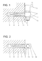
- a hook-shaped Device As shown in Fig. 1, there is a hook-shaped Device according to the invention of three Elements (1, 2, 3), of which the element (1) in a dowel (6) is screwed in one hole (5) made in the wall (4).
- the part protruding from the wall (4) (12) of the element (1) has a square Cross section and has a transverse to the longitudinal direction the threaded bore (13) of the element (1) on (Fig. 2).
- the position of the Hakens (31) changed in height and to the Height of the hook already in the wall (4) located further device can be adapted.
- FIG. 2 shows a top view of how the threaded bore (13) in the first element (1) is arranged, in which the bolt shown in Fig. 3 (21) of the second element (2) with its thread (23) can be screwed in.
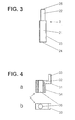
- FIG. 3 shows the complete in a side view second element (2) coming from the bolt (21) with its thread (23) and from which on the attached an end face of the bolt (21) smooth pin (22), which is shown in Fig. 4 third element (3) with its continuous Bore (35) receives.
- Fig. 4 shows this from the right-angled hook (31) and the approach (34) existing third element (3) in a partially sectioned side view (a) and in a top view (b).
Landscapes
- Engineering & Computer Science (AREA)
- General Engineering & Computer Science (AREA)
- Mechanical Engineering (AREA)
- Supports Or Holders For Household Use (AREA)
- Connection Of Plates (AREA)
Claims (16)
- Dispositifs en forme de crochets, permettant de suspendre des objets à un mur, composé de trois éléments (1, 2, 3).a) le premier élément (1) a en gros la forme d'une tige rentrant pratiquement entièrement dans le mur (4), la partie restant en-dehors (12) du mur (4) étant pourvue d'un trou taraudé (13) dans le sens perpendiculaire à son axe longitudinal,b) le deuxième élément (2) se compose d'un boulon cylindrique (21 ) dont une extrémité porte un téton lisse (22), monté dans le sens axial et dont la surface cylindrique est filetée, le filetage (23) se vissant dans le trou taraudé (13) du premier élément (1), etc) le troisième élément (3) comprend un crochet en équerre (31 ) dont l'un des côtés (32) présente un talon (34) allant dans la direction opposée à l'autre côté (33), de longueur approximativement égale à celle du téton (22) du deuxième élément (2), et percé d'un trou, de préférence traversant (35), dont le diamètre est choisi de façon à ce que le talon (34) s'enfile pratiquement sans jeu sur le téton (22).
- Dispositif selon la revendication 1, caractérisé en ce que la partie (11 ) rentrant dans le mur (4) du premier élément (1) est munie d'un filetage qui se visse dans une cheville (6) montée dans un alésage cylindrique (5) percé dans le mur (4).
- Dispositif selon la revendication 1, caractérisé en ce que la partie (11 ) rentrant dans le mur (4) du premier élément (1) est dotée d'une surface cannelée et enfoncée dans une cheville (6) fixée dans l'alésage cylindrique (5) percé dans le mur (4).
- Dispositif selon la revendication 1, caractérisé en ce que la partie (11) rentrant dans le mur (4) du premier élément (1) est dotée d'une surface cannelée, puis plâtrée ou cimentée dans l'alésage cylindrique (5) percé dans le mur (4).
- Dispositif selon l'une des revendications 1 à 4, caractérisé en ce que la partie (12) sortant du mur (4) du premier élément (1) a une section rectangulaire, ou de préférence carrée, deux des faces opposées étant parallèles à l'axe du trou taraudé (13).
- Dispositif selon l'une des revendications 1 à 5, caractérisé en ce que la face avant (14) de la partie (12) sortant du mur (4) du premier élément (1) est pourvue d'une fente, de préférence en croix, de la forme de la lame d'un tournevis pour pouvoir visser le premier élément dans une cheville.
- Dispositif selon l'une des revendications 1 à 6, caractérisé en ce que la face avant libre (24, 25) du boulon (21) et/ou du téton (22) du deuxième élément (2) d'une fente, de préférence en croix, de la forme de la lame d'un tournevis.
- Dispositif selon l'une des revendications 1 à 7, caractérisé en ce que le talon (34) du troisième élément (3) est de section rectangulaire et va presque jusqu'au mur (4).
- Dispositif selon l'une des revendications précédentes, caractérisé en ce que le téton (22) est coaxial au boulon (21) et a un diamètre inférieur.
- Dispositif selon l'une des revendications précédentes, caractérisé en ce que l'on place des rondelles ou bagues coaxiales, faisant saillie dans le sens radial, sur le boulon (21) et/ou le téton (22), ces rondelles ou bagues servant de butée.
- Dispositif selon l'une des revendications précédentes, caractérisé en ce que le troisième élément (3) est relié au deuxième élément (2), par ex. par une vis.
- Dispositif selon l'une des revendications précédentes, caractérisé en ce que le diamètre du téton (22) représente 50 à 75 % du diamètre du boulon (21).
- Dispositif selon l'une des revendications précédentes, caractérisé en ce que la largeur de l'ouverture du troisième élément (3), c.-à-d. la somme du rayon de la surface extérieure du talon (34) et de la distance de la surface de délimitation intérieure de l'autre côté (33) par rapport à l'axe de l'alésage (35), est supérieure à l'épaisseur du crochet de fixation qui doit y rentrer.
- Dispositif selon l'une des revendications précédentes, caractérisé en ce que le rayon de la surface extérieure du talon est inférieur à la distance entre la surface de délimitation intérieure de l'autre côté (33) et l'axe de l'alésage (35).
- Dispositif selon la revendication 14, caractérisé en ce que la distance entre la surface de délimitation intérieure de l'autre côté (33), moins le rayon de la surface extérieure du talon (34), est supérieure à l'épaisseur du crochet de fixation qui doit y rentrer.
- Dispositif selon l'une des revendications précédentes, caractérisé en ce que la surface frontale de délimitation supérieure, constituée par le talon (34) et un côté (32), forme un plan horizontal.
Applications Claiming Priority (2)
| Application Number | Priority Date | Filing Date | Title |
|---|---|---|---|
| DE29716027U DE29716027U1 (de) | 1997-09-05 | 1997-09-05 | Hakenförmige Vorrichtungen zum Anbringen von Gegenständen an einer Wand |
| DE29716027U | 1997-09-05 |
Publications (2)
| Publication Number | Publication Date |
|---|---|
| EP0900539A1 EP0900539A1 (fr) | 1999-03-10 |
| EP0900539B1 true EP0900539B1 (fr) | 2001-02-07 |
Family
ID=8045638
Family Applications (1)
| Application Number | Title | Priority Date | Filing Date |
|---|---|---|---|
| EP98116635A Expired - Lifetime EP0900539B1 (fr) | 1997-09-05 | 1998-09-03 | Dispositif en forme de crochet pour fixer des objets à une paroi |
Country Status (3)
| Country | Link |
|---|---|
| EP (1) | EP0900539B1 (fr) |
| AT (1) | ATE199055T1 (fr) |
| DE (2) | DE29716027U1 (fr) |
Families Citing this family (7)
| Publication number | Priority date | Publication date | Assignee | Title |
|---|---|---|---|---|
| DE10031888A1 (de) * | 2000-06-30 | 2002-01-10 | Harald F Bruecksken | Schraubhaken |
| BE1015319A5 (nl) * | 2003-01-20 | 2005-01-11 | Demeulenaere Eddy | Bekistingsschroef. |
| FR2855569B1 (fr) * | 2003-05-27 | 2006-11-24 | Jean Pierre Jager | Dispositif support pour tablette ou autre |
| GB2507281A (en) * | 2012-10-24 | 2014-04-30 | David Symonds | Adjustable wall hanging mechanism |
| CN105078037B (zh) * | 2015-09-07 | 2019-04-09 | 重庆市腾瀚工贸有限公司 | 定高支撑连接器 |
| DE202016007221U1 (de) | 2016-11-25 | 2017-01-26 | Ulrich Bauer | Hakenförmige Vorrichtung |
| BR102017016782A2 (pt) * | 2017-08-04 | 2019-03-26 | Jorge Joubert Raphaelian | Suporte com meio de regulagem de nível para montagem de quadro decorativo em plano vertical |
Family Cites Families (10)
| Publication number | Priority date | Publication date | Assignee | Title |
|---|---|---|---|---|
| DD53861A (fr) * | ||||
| DE455765C (de) * | 1928-02-07 | Gustav Reisser | Einrichtung zur Befestigung von Spiegel- und sonstigen Glasplatten an einer Wand | |
| US1565108A (en) * | 1925-02-13 | 1925-12-08 | James L Riley | Adjustable wall bracket |
| US2723096A (en) * | 1951-08-02 | 1955-11-08 | Schwartz Jack | Hanger for mirrors and the like |
| DE1935589A1 (de) * | 1969-07-12 | 1971-01-21 | Christian Rechmeier | Verstellbarer Aufhaengebeschlag |
| DE3909957C2 (de) * | 1989-03-27 | 1997-07-17 | E Norm Beschlag Gmbh | Vorrichtung zum Aufhängen von Schränken |
| DE9209477U1 (de) * | 1992-07-15 | 1993-02-04 | Runge, Petra, 5000 Köln | Scharnier (für Spiegelbuch) |
| FR2701520B1 (fr) * | 1993-02-12 | 1995-04-07 | Ludmann Ets Robert | Dispositif de fixation notamment de tablettes, d'étagères ou autres. |
| DE4447208C2 (de) * | 1994-12-30 | 1998-07-16 | Alfer Aluminium Gmbh | Hakenträgersystem |
| EP0847248B1 (fr) * | 1995-08-29 | 2003-04-16 | Philippe Holder | Organe de support et dispositif de support et de positionnement de tableaux |
-
1997
- 1997-09-05 DE DE29716027U patent/DE29716027U1/de not_active Expired - Lifetime
-
1998
- 1998-09-03 DE DE59800462T patent/DE59800462D1/de not_active Expired - Fee Related
- 1998-09-03 AT AT98116635T patent/ATE199055T1/de not_active IP Right Cessation
- 1998-09-03 EP EP98116635A patent/EP0900539B1/fr not_active Expired - Lifetime
Also Published As
| Publication number | Publication date |
|---|---|
| EP0900539A1 (fr) | 1999-03-10 |
| DE29716027U1 (de) | 1997-11-06 |
| ATE199055T1 (de) | 2001-02-15 |
| DE59800462D1 (de) | 2001-03-15 |
Similar Documents
| Publication | Publication Date | Title |
|---|---|---|
| WO1995022702A1 (fr) | Element de liaison filete des deux cotes | |
| EP0099972B1 (fr) | Elément d'assemblage pour plaques | |
| DE60011003T2 (de) | Permanente Verankerungsvorrichtung | |
| EP0501148A1 (fr) | Système d'assemblage pour deux éléments fabriqués en tube ou tige et/ou éléments ayant des jonctions | |
| EP0900539B1 (fr) | Dispositif en forme de crochet pour fixer des objets à une paroi | |
| DE3821872A1 (de) | Befestigungselement fuer trockenwaende | |
| DE2812502C2 (fr) | ||
| DE3822831A1 (de) | Eingriffsgesicherte befestigung und werkzeug zur bedienung derselben | |
| CH666523A5 (de) | Anordnung zur kreuzverbindung mindestens zweier stabfoermiger profile mit einem knotenkoerper. | |
| DE10327312A1 (de) | Abstandelement | |
| DE3333055C2 (de) | Vorrichtung zum Befestigen von Latten | |
| DE2921599C2 (fr) | ||
| AT402335B (de) | Justierdübelsystem zur einstellbaren verbindung zweier elemente miteinander sowie eine gewindehülse, eine verankerungshülse, ein verankerungselement und eine bohrhilfe für das justierdübelsystem | |
| DE2834331C2 (fr) | ||
| DE9114624U1 (de) | Befestigungselement | |
| DE3429228A1 (de) | Fachwerk, insbesondere raumfachwerk aus rohrstaeben und knotenstuecken | |
| EP2530223B1 (fr) | Clôture de sécurité | |
| EP2644060B1 (fr) | Dispositif de fixation | |
| DE3127873C2 (fr) | ||
| DE9317744U1 (de) | Vorrichtung zur Befestigung von Aufhängern an Holzpaneelverkleidungen | |
| DE3502436A1 (de) | Aufhaengevorrichtung fuer die anbringung an wandplatten und lehre zur anbringung der aufhaengevorrichtung | |
| DE2019367A1 (de) | Loesbare Verbindung zwischen zwei Staeben aus Metall oder Kunststoff mit einer gewissen Eigenelastizitaet | |
| CH449334A (de) | Spreizkupplung | |
| DE2734520C3 (de) | Schalungszuganker aus Kunststoff | |
| DE202018103878U1 (de) | Absperrpfosten |
Legal Events
| Date | Code | Title | Description |
|---|---|---|---|
| PUAI | Public reference made under article 153(3) epc to a published international application that has entered the european phase |
Free format text: ORIGINAL CODE: 0009012 |
|
| AK | Designated contracting states |
Kind code of ref document: A1 Designated state(s): AT BE CH DE DK FI FR GB IE IT LI NL SE |
|
| AX | Request for extension of the european patent |
Free format text: AL;LT;LV;MK;RO;SI |
|
| 17P | Request for examination filed |
Effective date: 19990206 |
|
| 17Q | First examination report despatched |
Effective date: 19990922 |
|
| AKX | Designation fees paid |
Free format text: AT BE CH DE DK FI FR GB IE IT LI NL SE |
|
| GRAG | Despatch of communication of intention to grant |
Free format text: ORIGINAL CODE: EPIDOS AGRA |
|
| 17Q | First examination report despatched |
Effective date: 19990922 |
|
| GRAG | Despatch of communication of intention to grant |
Free format text: ORIGINAL CODE: EPIDOS AGRA |
|
| GRAH | Despatch of communication of intention to grant a patent |
Free format text: ORIGINAL CODE: EPIDOS IGRA |
|
| GRAH | Despatch of communication of intention to grant a patent |
Free format text: ORIGINAL CODE: EPIDOS IGRA |
|
| GRAA | (expected) grant |
Free format text: ORIGINAL CODE: 0009210 |
|
| AK | Designated contracting states |
Kind code of ref document: B1 Designated state(s): AT BE CH DE DK FI FR GB IE IT LI NL SE |
|
| PG25 | Lapsed in a contracting state [announced via postgrant information from national office to epo] |
Ref country code: SE Free format text: THE PATENT HAS BEEN ANNULLED BY A DECISION OF A NATIONAL AUTHORITY Effective date: 20010207 Ref country code: NL Free format text: LAPSE BECAUSE OF FAILURE TO SUBMIT A TRANSLATION OF THE DESCRIPTION OR TO PAY THE FEE WITHIN THE PRESCRIBED TIME-LIMIT Effective date: 20010207 Ref country code: IT Free format text: LAPSE BECAUSE OF FAILURE TO SUBMIT A TRANSLATION OF THE DESCRIPTION OR TO PAY THE FEE WITHIN THE PRESCRIBED TIME-LIMIT;WARNING: LAPSES OF ITALIAN PATENTS WITH EFFECTIVE DATE BEFORE 2007 MAY HAVE OCCURRED AT ANY TIME BEFORE 2007. THE CORRECT EFFECTIVE DATE MAY BE DIFFERENT FROM THE ONE RECORDED. Effective date: 20010207 Ref country code: IE Free format text: LAPSE BECAUSE OF FAILURE TO SUBMIT A TRANSLATION OF THE DESCRIPTION OR TO PAY THE FEE WITHIN THE PRESCRIBED TIME-LIMIT Effective date: 20010207 Ref country code: FI Free format text: LAPSE BECAUSE OF FAILURE TO SUBMIT A TRANSLATION OF THE DESCRIPTION OR TO PAY THE FEE WITHIN THE PRESCRIBED TIME-LIMIT Effective date: 20010207 |
|
| REF | Corresponds to: |
Ref document number: 199055 Country of ref document: AT Date of ref document: 20010215 Kind code of ref document: T |
|
| REG | Reference to a national code |
Ref country code: CH Ref legal event code: EP |
|
| REF | Corresponds to: |
Ref document number: 59800462 Country of ref document: DE Date of ref document: 20010315 |
|
| GBT | Gb: translation of ep patent filed (gb section 77(6)(a)/1977) |
Effective date: 20010223 |
|
| REG | Reference to a national code |
Ref country code: IE Ref legal event code: FG4D Free format text: GERMAN |
|
| PG25 | Lapsed in a contracting state [announced via postgrant information from national office to epo] |
Ref country code: DK Free format text: LAPSE BECAUSE OF FAILURE TO SUBMIT A TRANSLATION OF THE DESCRIPTION OR TO PAY THE FEE WITHIN THE PRESCRIBED TIME-LIMIT Effective date: 20010507 |
|
| ET | Fr: translation filed | ||
| NLV1 | Nl: lapsed or annulled due to failure to fulfill the requirements of art. 29p and 29m of the patents act | ||
| PG25 | Lapsed in a contracting state [announced via postgrant information from national office to epo] |
Ref country code: BE Free format text: LAPSE BECAUSE OF NON-PAYMENT OF DUE FEES Effective date: 20010930 |
|
| REG | Reference to a national code |
Ref country code: IE Ref legal event code: FD4D |
|
| PLBE | No opposition filed within time limit |
Free format text: ORIGINAL CODE: 0009261 |
|
| STAA | Information on the status of an ep patent application or granted ep patent |
Free format text: STATUS: NO OPPOSITION FILED WITHIN TIME LIMIT |
|
| REG | Reference to a national code |
Ref country code: GB Ref legal event code: IF02 |
|
| 26N | No opposition filed | ||
| BERE | Be: lapsed |
Owner name: NAWRATH GEORG Effective date: 20010930 |
|
| PG25 | Lapsed in a contracting state [announced via postgrant information from national office to epo] |
Ref country code: LI Free format text: LAPSE BECAUSE OF NON-PAYMENT OF DUE FEES Effective date: 20020930 Ref country code: CH Free format text: LAPSE BECAUSE OF NON-PAYMENT OF DUE FEES Effective date: 20020930 |
|
| REG | Reference to a national code |
Ref country code: CH Ref legal event code: PL |
|
| PGFP | Annual fee paid to national office [announced via postgrant information from national office to epo] |
Ref country code: AT Payment date: 20050922 Year of fee payment: 8 |
|
| PGFP | Annual fee paid to national office [announced via postgrant information from national office to epo] |
Ref country code: GB Payment date: 20050923 Year of fee payment: 8 |
|
| PG25 | Lapsed in a contracting state [announced via postgrant information from national office to epo] |
Ref country code: AT Free format text: LAPSE BECAUSE OF NON-PAYMENT OF DUE FEES Effective date: 20060903 |
|
| PGFP | Annual fee paid to national office [announced via postgrant information from national office to epo] |
Ref country code: FR Payment date: 20060922 Year of fee payment: 9 |
|
| GBPC | Gb: european patent ceased through non-payment of renewal fee |
Effective date: 20060903 |
|
| PGFP | Annual fee paid to national office [announced via postgrant information from national office to epo] |
Ref country code: DE Payment date: 20070920 Year of fee payment: 10 |
|
| PG25 | Lapsed in a contracting state [announced via postgrant information from national office to epo] |
Ref country code: GB Free format text: LAPSE BECAUSE OF NON-PAYMENT OF DUE FEES Effective date: 20060903 |
|
| REG | Reference to a national code |
Ref country code: FR Ref legal event code: ST Effective date: 20080531 |
|
| PG25 | Lapsed in a contracting state [announced via postgrant information from national office to epo] |
Ref country code: FR Free format text: LAPSE BECAUSE OF NON-PAYMENT OF DUE FEES Effective date: 20071001 |
|
| PG25 | Lapsed in a contracting state [announced via postgrant information from national office to epo] |
Ref country code: DE Free format text: LAPSE BECAUSE OF NON-PAYMENT OF DUE FEES Effective date: 20090401 |