EP0900539B1 - Hook-shaped device for mounting objects to a wall - Google Patents
Hook-shaped device for mounting objects to a wall Download PDFInfo
- Publication number
- EP0900539B1 EP0900539B1 EP98116635A EP98116635A EP0900539B1 EP 0900539 B1 EP0900539 B1 EP 0900539B1 EP 98116635 A EP98116635 A EP 98116635A EP 98116635 A EP98116635 A EP 98116635A EP 0900539 B1 EP0900539 B1 EP 0900539B1
- Authority
- EP
- European Patent Office
- Prior art keywords
- wall
- shoulder
- journal
- bore
- leg
- Prior art date
- Legal status (The legal status is an assumption and is not a legal conclusion. Google has not performed a legal analysis and makes no representation as to the accuracy of the status listed.)
- Expired - Lifetime
Links
- 238000013459 approach Methods 0.000 description 6
- 210000002414 leg Anatomy 0.000 description 5
- 210000000689 upper leg Anatomy 0.000 description 2
- 210000000078 claw Anatomy 0.000 description 1
- 238000011161 development Methods 0.000 description 1
- 238000005553 drilling Methods 0.000 description 1
- 239000011521 glass Substances 0.000 description 1
- 238000003780 insertion Methods 0.000 description 1
- 230000037431 insertion Effects 0.000 description 1
- 239000000463 material Substances 0.000 description 1
- 238000000034 method Methods 0.000 description 1
- 230000006641 stabilisation Effects 0.000 description 1
- 238000011105 stabilization Methods 0.000 description 1
- 238000003756 stirring Methods 0.000 description 1
- 238000012546 transfer Methods 0.000 description 1
- 230000007704 transition Effects 0.000 description 1
Images
Classifications
-
- F—MECHANICAL ENGINEERING; LIGHTING; HEATING; WEAPONS; BLASTING
- F16—ENGINEERING ELEMENTS AND UNITS; GENERAL MEASURES FOR PRODUCING AND MAINTAINING EFFECTIVE FUNCTIONING OF MACHINES OR INSTALLATIONS; THERMAL INSULATION IN GENERAL
- F16B—DEVICES FOR FASTENING OR SECURING CONSTRUCTIONAL ELEMENTS OR MACHINE PARTS TOGETHER, e.g. NAILS, BOLTS, CIRCLIPS, CLAMPS, CLIPS OR WEDGES; JOINTS OR JOINTING
- F16B35/00—Screw-bolts; Stay-bolts; Screw-threaded studs; Screws; Set screws
- F16B35/04—Screw-bolts; Stay-bolts; Screw-threaded studs; Screws; Set screws with specially-shaped head or shaft in order to fix the bolt on or in an object
- F16B35/06—Specially-shaped heads
-
- A—HUMAN NECESSITIES
- A47—FURNITURE; DOMESTIC ARTICLES OR APPLIANCES; COFFEE MILLS; SPICE MILLS; SUCTION CLEANERS IN GENERAL
- A47G—HOUSEHOLD OR TABLE EQUIPMENT
- A47G1/00—Mirrors; Picture frames or the like, e.g. provided with heating, lighting or ventilating means
- A47G1/16—Devices for hanging or supporting pictures, mirrors, or the like
- A47G1/20—Picture hooks; X-hooks
- A47G1/202—Picture hooks; X-hooks adjustable
-
- F—MECHANICAL ENGINEERING; LIGHTING; HEATING; WEAPONS; BLASTING
- F16—ENGINEERING ELEMENTS AND UNITS; GENERAL MEASURES FOR PRODUCING AND MAINTAINING EFFECTIVE FUNCTIONING OF MACHINES OR INSTALLATIONS; THERMAL INSULATION IN GENERAL
- F16B—DEVICES FOR FASTENING OR SECURING CONSTRUCTIONAL ELEMENTS OR MACHINE PARTS TOGETHER, e.g. NAILS, BOLTS, CIRCLIPS, CLAMPS, CLIPS OR WEDGES; JOINTS OR JOINTING
- F16B13/00—Dowels or other devices fastened in walls or the like by inserting them in holes made therein for that purpose
- F16B13/12—Separate metal or non-separate or non-metal dowel sleeves fastened by inserting the screw, nail or the like
- F16B13/124—Separate metal or non-separate or non-metal dowel sleeves fastened by inserting the screw, nail or the like fastened by inserting a threaded element, e.g. screw or bolt
-
- F—MECHANICAL ENGINEERING; LIGHTING; HEATING; WEAPONS; BLASTING
- F16—ENGINEERING ELEMENTS AND UNITS; GENERAL MEASURES FOR PRODUCING AND MAINTAINING EFFECTIVE FUNCTIONING OF MACHINES OR INSTALLATIONS; THERMAL INSULATION IN GENERAL
- F16B—DEVICES FOR FASTENING OR SECURING CONSTRUCTIONAL ELEMENTS OR MACHINE PARTS TOGETHER, e.g. NAILS, BOLTS, CIRCLIPS, CLAMPS, CLIPS OR WEDGES; JOINTS OR JOINTING
- F16B37/00—Nuts or like thread-engaging members
Definitions
- the invention relates to hook-shaped devices for attaching objects to a wall.
- Such devices are in numerous forms in the trade and consist for example of screw hooks, the dowels inserted into the wall become. It often happens that the Attaching a larger item, for example a wide picture, at least two of them Screw hooks are required, which are after the Experience has shown that it is screwed into the appropriate dowels are rarely at exactly the same height, so that the picture hung on it invariably crooked hangs. This unsatisfactory result mostly stirs therefore that during drilling the for the Dowels needed holes in the drill because of the inhomogeneous Wall material to the side and / or down drifts away, as every handyman and handyman knows.
- DE 455 765 describes a device for fastening known from mirror plates on a wall. It consists of a plate edge Claw provided with a cylindrical bore is that attachable to a pin of a wall arm is, the wall arm adjustable in height on the Wall is attached. With this facility, however only mirror or other glass plates attachable to a wall.
- a fastener for pictures or the like described. It consists of an intermediate piece that with an essentially vertical threaded bore is provided. This intermediate piece is fixable to the wall with a fastener. In the hole is one with a through Threaded threaded rod can be screwed in. The The picture to be hung will then be on or at the top of the threaded rod.
- the invention is based, devices of the type mentioned at the beginning, with whose help each object is precisely on one Wall can be attached, that is, for example horizontal or vertical course the edges of this item, only for this some simple, even layman executable Handles are required.
- the engaging in the wall Part of the first element is a screw thread has that in a in the wall cylindrical bore inserted screw plug is.
- the part of the first element which engages in the wall has a corrugated surface and in one into a cylindrical one in the wall Bore used dowels can be driven.
- the in the wall engaging part of the first element has a corrugated surface and in a wall-mounted cylindrical hole plasterable or can be cemented.
- the part protruding from the wall of the first element on its face one Blade of a screwdriver receiving slot, preferably cross recess.
- the bolt and / or the pin of the second element on the free end face a receiving the blade of a screwdriver Have slot, preferably cross slot.
- the pin has a smaller diameter than the bolt, so that as a result at the transition between tenons and bolts as a stop surface for the third element a paragraph is formed, which makes it more advantageous Way allowed comparatively large forces to transfer from the third to the second element.
- a relief here to create is a possibly releasable Connection between the second and third element, for example, proposed a screw connection.
- the diameter of the former Relative to the dimensions of the tenon for bolting is advantageous the diameter of the former with 50 to 75% of that of the latter too choose.
- the diameter of the pin should be not too small to be chosen without problems on the front of the pin with a screwdriver to be able to attack. would be the diameter the pin is too small, the slot would be too short to pick up the screwdriver and a satisfactory one To ensure screwing in. In case of comparatively small dimensions of the proposed hook-shaped device becomes the diameter choose a comparatively large pin.
- the opening width of the third element leading to Picking up the object to be attached using a hook is preferably chosen so that it is greater than the strength of the fastening hook to be picked up.
- the term "strength" means in the sense of the invention the distance between the Hook the device to penetrate through and the upper boundary surface of the hook in the plane of the hook.
- the opening width adds up itself from the radius of the outer surface of the approach plus the distance of the inner boundary surface of the other leg from the axis of the bore.
- the radius of the outer surface of the neck is smaller is the distance of the inner boundary surface of the other leg from the axis of the bore. This difference is more than the thickness the fastening hook of the object to be attached (measured perpendicular to that through the fastening hook described plane) is an exactly vertical one Alignment possible without additional measures.
- the dated Approach and the upper leg formed one frontal boundary surface a horizontal Level is.
- an appropriate that is also called a horizontal contact surface Fastening hook there is a stabilization against rotation around a horizontal Axis, that is, a pivoting of the to be attached Object, especially what of Meaning is if only a single attachment point is provided. Swiveling the object, such as B. the image is largely prevented; an exact horizontal alignment of the There is no need for a picture frame.
- a hook-shaped Device As shown in Fig. 1, there is a hook-shaped Device according to the invention of three Elements (1, 2, 3), of which the element (1) in a dowel (6) is screwed in one hole (5) made in the wall (4).
- the part protruding from the wall (4) (12) of the element (1) has a square Cross section and has a transverse to the longitudinal direction the threaded bore (13) of the element (1) on (Fig. 2).
- the position of the Hakens (31) changed in height and to the Height of the hook already in the wall (4) located further device can be adapted.
- FIG. 2 shows a top view of how the threaded bore (13) in the first element (1) is arranged, in which the bolt shown in Fig. 3 (21) of the second element (2) with its thread (23) can be screwed in.
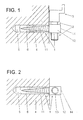
- FIG. 3 shows the complete in a side view second element (2) coming from the bolt (21) with its thread (23) and from which on the attached an end face of the bolt (21) smooth pin (22), which is shown in Fig. 4 third element (3) with its continuous Bore (35) receives.
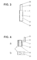
- Fig. 4 shows this from the right-angled hook (31) and the approach (34) existing third element (3) in a partially sectioned side view (a) and in a top view (b).
Landscapes
- Engineering & Computer Science (AREA)
- General Engineering & Computer Science (AREA)
- Mechanical Engineering (AREA)
- Supports Or Holders For Household Use (AREA)
- Connection Of Plates (AREA)
Abstract
Description
Die Erfindung betrifft hakenförmige Vorrichtungen zum Anbringen von Gegenständen an einer Wand.The invention relates to hook-shaped devices for attaching objects to a wall.
Derartige Vorrichtungen sind in zahlreichen Formen im Handel und bestehen beispielsweise aus Schraubhaken, die in in die Wand eingesetzte Dübel eingeschraubt werden. Dabei kommt es häufig vor, daß zum Anbringen eines größeren Gegenstandes, beispielsweise eines breiten Bildes, wenigstens zwei solcher Schraubhaken erforderlich sind, die sich nach dem Einschrauben in entsprechende Dübel erfahrungsgemäß nur selten in genau gleicher Höhe befinden, so daß das daran aufgehängte Bild unabänderlich schief hängt. Dieses unbefriedigende Ergebnis rührt meistens daher, daß während des Bohrens der für die Dübel benötigten Löcher der Bohrer wegen des unhomogenen Wandmaterials zur Seite und/oder nach unten wegdriftet, wie jeder Hand- und Heimwerker weiß.Such devices are in numerous forms in the trade and consist for example of screw hooks, the dowels inserted into the wall become. It often happens that the Attaching a larger item, for example a wide picture, at least two of them Screw hooks are required, which are after the Experience has shown that it is screwed into the appropriate dowels are rarely at exactly the same height, so that the picture hung on it invariably crooked hangs. This unsatisfactory result mostly stirs therefore that during drilling the for the Dowels needed holes in the drill because of the inhomogeneous Wall material to the side and / or down drifts away, as every handyman and handyman knows.
Aus der DE 455 765 ist eine Einrichtung zur Befestigung von Spiegelplatten an einer Wand bekannt. Sie besteht aus einer den Plattenrand umfassenden Klaue, die mit einer zylindrischen Bohrung versehen ist, die auf einen Zapfen eines Wandarms aufsteckbar ist, wobei der Wandarm höhenverstellbar an der Wand befestigt ist. Mit dieser Einrichtung sind jedoch lediglich Spiegel- oder sonstige Glasplatten an einer Wand befestigbar. In der WO 97 07720 ist ein Befestigungselement für Bilder odgl. beschrieben. Es besteht aus einem Zwischenstück, das mit einer im wesentlichen vertikal verlaufenden Gewindebohrung versehen ist. Dieses Zwischenstück ist mit einem Befestigungselement an der Wand fixierbar. In die Bohrung ist ein mit einem durchgehenden Gewinde versehener Gewindestab einschraubbar. Das aufzuhängende Bild wird dann auf oder an der Spitze des Gewindestabs abgestützt. Hierbei ist als nachteilig anzusehen, daß zur Befestigung des Zwischenstückes an der Wand ein weiteres Bauteil notwendig ist, jedoch soll das Prinzip der Höhenverstellbarkeit der Aufhängevorrichtung, d. h. das Verdrehen eines Gewindestabes in einer Bohrung, bei der vorliegenden Erfindung verwendet werden.DE 455 765 describes a device for fastening known from mirror plates on a wall. It consists of a plate edge Claw provided with a cylindrical bore is that attachable to a pin of a wall arm is, the wall arm adjustable in height on the Wall is attached. With this facility, however only mirror or other glass plates attachable to a wall. In WO 97 07720 a fastener for pictures or the like. described. It consists of an intermediate piece that with an essentially vertical threaded bore is provided. This intermediate piece is fixable to the wall with a fastener. In the hole is one with a through Threaded threaded rod can be screwed in. The The picture to be hung will then be on or at the top of the threaded rod. This is considered a disadvantage to see that for fastening the intermediate piece Another component is necessary on the wall is, however, the principle of height adjustability the hanger, d. H. the twisting a threaded rod in a hole, in the present Invention can be used.
Der Erfindung liegt die Aufgabe zugrunde, Vorrichtungen der eingangs erwähnten Art anzugeben, mit deren Hilfe jeder Gegenstand genau gerade an einer Wand angebracht werden kann, das heißt mit beispielsweise waagerechtem bzw. senkrechtem Verlauf der Kanten dieses Gegenstandes, wobei hierfür nur einige einfache, auch von einem Laien ausführbare Handgriffe erforderlich sind.The invention is based, devices of the type mentioned at the beginning, with whose help each object is precisely on one Wall can be attached, that is, for example horizontal or vertical course the edges of this item, only for this some simple, even layman executable Handles are required.
Diese Aufgabe wird gemäß Anspruch 1 dadurch gelöst,
daß die Vorrichtungen aus je drei Elementen zusammensetzbar
sind, wobei
Nach einer vorteilhaften Weiterbildung der Erfindung ist vorgesehen, daß der in die Wand eingreifende Teil des ersten Elementes ein Schraubgewinde aufweist, das in einen in eine in der Wand befindliche zylindrische Bohrung eingesetzten Dübel einschraubbar ist.According to an advantageous development of the invention it is intended that the engaging in the wall Part of the first element is a screw thread has that in a in the wall cylindrical bore inserted screw plug is.
Nach einer anderen Alternative ist vorgesehen, daß der in die Wand eingreifende Teil des ersten Elementes eine geriffelte Oberfläche aufweist und in einen in eine in der Wand befindliche zylindrische Bohrung eingesetzten Dübel einschlagbar ist.According to another alternative it is provided that the part of the first element which engages in the wall has a corrugated surface and in one into a cylindrical one in the wall Bore used dowels can be driven.
Es besteht aber auch die Möglichkeit, daß der in die Wand eingreifende Teil des ersten Elementes eine geriffelte Oberfläche aufweist und in eine in der Wand befindliche zylindrische Bohrung eingipsbar oder einzementierbar ist.But there is also the possibility that the in the wall engaging part of the first element has a corrugated surface and in a wall-mounted cylindrical hole plasterable or can be cemented.
Um das in die Wand eingeschraubte erste Element besser ausrichten zu können, ist ferner vorgesehen, daß der aus der Wand herausstehende Teil des ersten Elementes einen rechteckigen, vorzugsweise quadratischen Querschnitt hat, wobei zwei seiner jeweils gegenüberliegenden Seitenflächen parallel zur Achse der Gewindebohrung verlaufen.Around the first element screwed into the wall It is also planned to be able to better align that the part of the first protruding from the wall Element a rectangular, preferably square Has cross section, two of its each opposite side faces parallel to the axis the threaded hole.
Um das erste Element in einen Dübel einschrauben zu können, weist der aus der Wand herausstehende Teil des ersten Elementes an seiner Stirnseite einen die Klinge eines Schraubendrehers aufnehmenden Schlitz, vorzugsweise Kreuzschlitz, auf.To screw the first element into a dowel can, the part protruding from the wall of the first element on its face one Blade of a screwdriver receiving slot, preferably cross recess.
Zum Einschrauben des zweiten Elementes in die Gewindebohrung des ersten Elementes bzw. zum Verstellen des bereits eingeschraubten zweiten Elementes ist vorgesehen, daß der Bolzen und/oder der Zapfen des zweiten Elementes an der jeweils freien Stirnseite einen die Klinge eines Schraubendrehers aufnehmenden Schlitz, vorzugsweise Kreuzschlitz, aufweisen.For screwing the second element into the threaded hole of the first element or for adjustment of the second element already screwed in it is provided that the bolt and / or the pin of the second element on the free end face a receiving the blade of a screwdriver Have slot, preferably cross slot.
Damit der rechtwinklige Haken des dritten Elementes immer von der Wand absteht und sich nicht auf dem Zapfen des zweiten Elementes seitlich wegdrehen kann, ist ferner vorgesehen, daß der Ansatz des dritten Elementes einen rechteckigen Querschnitt hat und bis nahezu an die Wand heranreicht.So that the right-angled hook of the third element always protrudes from the wall and is not on the Turn the pin of the second element away to the side can, it is further provided that the approach of third element has a rectangular cross section has and almost reaches the wall.
Die mit der Erfindung erzielten Vorteile bestehen insbesondere darin, daß jeder aufzuhängende Gegenstand genau gerade an einer Wand angebracht werden kann, das heißt mit beispielsweise waagerechtem bzw. senkrechtem Verlauf der Kanten dieses Gegenstandes. Hierfür muß lediglich von den zwei verwendeten hakenförmigen Vorrichtungen wenigstens eine durch Verdrehen des zylindrischen Bolzens des zweiten Elementes dieser Bolzen soweit in der Höhe verändert werden, bis die Auflageflächen beider Haken auf gleicher Höhe liegen, wofür nur einige einfache, auch von einem Laien ausführbare Handgriffe mit einem Schraubendreher erforderlich sind.The advantages achieved with the invention exist especially in that every item to be hung to be mounted straight on a wall can, that is with, for example, horizontal or perpendicular course of the edges of this object. To do this, only of the two used hook-shaped devices at least one by rotating the cylindrical pin of the second Element of these bolts has changed in height until the contact surfaces of both hooks are at the same level, for which only a few simple, handles that can also be carried out by a layperson with a screwdriver.
In einer speziellen Ausgestaltung besitzt der Zapfen einen gegenüber dem Bolzen geringeren Durchmesser, so daß im Ergebnis am Übergang zwischen Zapfen und Bolzen als Anschlagsfläche für das dritte Element einen Absatz gebildet wird, der es in vorteilhafter Weise erlaubt, vergleichsweise große Kräfte vom dritten auf das zweite Element zu übertragen.In a special embodiment, the pin has a smaller diameter than the bolt, so that as a result at the transition between tenons and bolts as a stop surface for the third element a paragraph is formed, which makes it more advantageous Way allowed comparatively large forces to transfer from the third to the second element.
Eine Alternative zur Erzeugung eines Anschlages besteht darin, auf dem Bolzen und/oder dem Zapfen koaxial radial überstehende Scheiben oder Ringe anzubringen, die die Funktion eines Anschlages erfüllen. Sie dienen im Hinblick auf den Zapfen als Begrenzung der Einschraubtiefe des zweiten Elementes im herausstehenden Teil (12) des ersten Elementes und auf dem Zapfen als Begrenzung der Einstecktiefe des dritten Elementes hierauf.There is an alternative to creating a stop therein, coaxial on the bolt and / or the pin to attach radially protruding washers or rings, that perform the function of a stop. They serve as a limitation with regard to the pin the screw-in depth of the second element in the protruding part (12) of the first element and on the spigot as a limitation of the insertion depth of the third element thereon.
Beim Anbringen von Gegenständen an der hakenförmigen Vorrichtung gemäß der Erfindung besteht die große Gefahr, daß während des Einfädelns unmittelbar vor dem Einhängen das im allgemeinsten Fall lose aufgesteckte dritte Element versehentlich in axialer Richtung vom Zapfen nach oben herunter geschoben wird, mit der Folge, daß erneut das dritte Element aufzustecken ist und der Einfädelvorgang von neuem zu beginnen hat. Um hier eine Erleichterung zu schaffen, wird eine gegebenenfalls lösbare Verbindung zwischen dem zweiten und dritten Element, beispielsweise eine Verschraubung vorgeschlagen.When attaching objects to the hook-shaped Device according to the invention is the great danger that immediately during threading in the most general case before mounting loosely attached third element inadvertently pushed axially downwards from the pin with the result that the third Element and the threading process has to start again. A relief here to create, is a possibly releasable Connection between the second and third element, for example, proposed a screw connection.
Im Hinblick auf die Abmessungen vom Zapfen relativ zum Bolzen ist von Vorteil, den Durchmesser des ersteren mit 50 bis 75 % von dem des letzteren zu wählen. Hierbei gilt es einen Kompromiß zu schließen: Zum einen sollte der Durchmesser des Bolzens im Vergleich zum Zapfen groß gewählt werden, so daß eine vergleichsweise große Abstütz- und Auflagefläche zur Aufnahme großer Kräfte zur Verfügung steht. Andererseits sollte der Durchmesser des Zapfens jedoch nicht zu klein gewählt werden, um problemlos an der Stirnseite des Zapfens mit einem Schraubendreher angreifen zu können. Wäre der Durchmesser des Zapfens zu gering, wäre der Schlitz zu kurz, um den Schraubenzieher aufnehmen und ein befriedigendes Eindrehen sicherstellen zu können. Im Falle von vergleichsweise kleinen Abmessungen der vorgeschlagenen hakenförmigen Vorrichtung wird man den Durchmesser des Zapfens vergleichsweise groß wählen.Relative to the dimensions of the tenon for bolting is advantageous the diameter of the former with 50 to 75% of that of the latter too choose. A compromise must be made here: First, the diameter of the bolt be chosen large compared to the tenon, so that a comparatively large support and support area is available to absorb large forces. On the other hand, however, the diameter of the pin should be not too small to be chosen without problems on the front of the pin with a screwdriver to be able to attack. Would be the diameter the pin is too small, the slot would be too short to pick up the screwdriver and a satisfactory one To ensure screwing in. In case of comparatively small dimensions of the proposed hook-shaped device becomes the diameter choose a comparatively large pin.
Die Öffnungsweite des dritten Elementes, die zur Aufnahme des über einen Haken anzubringenden Gegenstandes dient, ist bevorzugt so zu wählen, daß sie größer ist als die Stärke des aufzunehmenden Befestigungshakens. Hierbei meint der Begriff "Stärke" im Sinne der Erfindung den Abstand zwischen der vom Haken der Vorrichtung zu durchgreifenden Öffnung und der oberen Begrenzungsflächedes Hakens, gemessen in der Ebene des Hakens. Die Öffnungsweite addiert sich aus dem Radius der Außenfläche des Ansatzes plus den Abstand der inneren Begrenzungsfläche des anderen Schenkels von der Achse der Bohrung. Der entscheidende Vorteil ist, daß der anzubringende Gegenstand, wie zum Beispiel ein Bild, in horizontaler Ausrichtung bei guter Einsehbarkeit eingefädelt werden kann und anschließend um 90° nach unten geklappt wird.The opening width of the third element leading to Picking up the object to be attached using a hook is preferably chosen so that it is greater than the strength of the fastening hook to be picked up. Here the term "strength" means in the sense of the invention the distance between the Hook the device to penetrate through and the upper boundary surface of the hook in the plane of the hook. The opening width adds up itself from the radius of the outer surface of the approach plus the distance of the inner boundary surface of the other leg from the axis of the bore. The key advantage is that the one to be attached Object, such as a picture, in horizontal alignment with good visibility can be threaded and then by 90 ° is folded down.
Beim Anbringen des Gegenstandes könnte sich zudem das Problem ergeben, daß der Gegenstand unterhalb des Hakens, so z. B. am zweiten Element und insbesondere am herausstehenden Teil des ersten Elementes zur Anlage kommt, so daß eine exakte vertikale Ausrichtung nicht mehr ohne weiteres möglich ist. Zur Beseitigung dieses Problemes ist von Vorteil, wenn der Radius der Außenfläche des Ansatzes kleiner ist als der Abstand der inneren Begrenzungsfläche des anderen Schenkels von der Achse der Bohrung. Beträgt diese Differenz mehr als die Dicke des Befestigungshaken des anzubringenden Gegenstandes (gemessen senkrecht zu der durch den Befestigungshaken beschriebenen Ebene) ist eine exakt vertikale Ausrichtung ohne zusätzlichen Maßnahmen möglich.When attaching the item could also the problem arise that the object below of the hook, e.g. B. on the second element and in particular on the protruding part of the first element comes to the plant, so that an exact vertical Alignment is no longer possible. To solve this problem, it is advantageous if the radius of the outer surface of the neck is smaller is the distance of the inner boundary surface of the other leg from the axis of the bore. This difference is more than the thickness the fastening hook of the object to be attached (measured perpendicular to that through the fastening hook described plane) is an exactly vertical one Alignment possible without additional measures.
Schließlich wird noch vorgeschlagen, daß die vom Ansatz und den einen Schenkel gebildete obere stirnseitige Begrenzungsfläche eine horizontale Ebene ist. Bei Verwendung eines entsprechenden, das heißt ebenfalls eine horizontale Kontaktfläche bildenden Befestigungshakens, ergibt sich eine Stabilisierung gegen Drehungen um eine horizontal verlaufende Achse, das heißt ein Verschwenken des anzubringenden Gegenstandes, was besonders dann von Bedeutung ist, wenn nur ein einziger Befestigungspunkt vorgesehen ist. Ein Verschwenken des Gegenstandes, wie z. B. des Bildes wird weitgehend unterbunden; eine exakte horizontale Ausrichtung des Bilderrahmens erübrigt sich. Finally, it is proposed that the dated Approach and the upper leg formed one frontal boundary surface a horizontal Level is. When using an appropriate that is also called a horizontal contact surface Fastening hook, there is a stabilization against rotation around a horizontal Axis, that is, a pivoting of the to be attached Object, especially what of Meaning is if only a single attachment point is provided. Swiveling the object, such as B. the image is largely prevented; an exact horizontal alignment of the There is no need for a picture frame.
Ein Ausführungsbeispiel der Erfindung ist in der Zeichnung dargestellt und wird im folgenden näher beschrieben. Es zeigen
- Fig. 1
- die Seitenansicht einer in eine Wand eingeschraubten hakenförmigen Vorrichtung gemäß der Erfindung,
- Fig. 2
- die Draufsicht auf das in eine Wand eingeschraubte erste Element der Vorrichtung nach Fig. 1,
- Fig. 3
- eine Seitenansicht, des zweiten Elementes der Vorrichtung nach Fig. 1 und
- Fig. 4
- verschiedene Ansichten des dritten Elementes der Vorrichtung nach Fig. 1.
- Fig. 1
- the side view of a hook-shaped device screwed into a wall according to the invention,
- Fig. 2
- the top view of the screwed into a wall first element of the device of FIG. 1,
- Fig. 3
- a side view of the second element of the device of FIG. 1 and
- Fig. 4
- different views of the third element of the device of FIG. 1st
Wie in Fig. 1 dargestellt ist, besteht eine hakenförmige Vorrichtung gemäß der Erfindung aus drei Elementen (1, 2, 3), von denen das Element (1) in einen Dübel (6) eingeschraubt ist, der sich in einer in die Wand (4) eingebrachten Bohrung (5) befindet. Der aus der Wand (4) herausstehende Teil (12) des Elementes (1) hat einen quadratischen Querschnitt und weist eine quer zur Längsrichtung des Elementes (1) verlaufende Gewindebohrung (13) auf (Fig. 2).As shown in Fig. 1, there is a hook-shaped Device according to the invention of three Elements (1, 2, 3), of which the element (1) in a dowel (6) is screwed in one hole (5) made in the wall (4). The part protruding from the wall (4) (12) of the element (1) has a square Cross section and has a transverse to the longitudinal direction the threaded bore (13) of the element (1) on (Fig. 2).
Das aus einem ein Gewinde (23) tragenden Bolzen (21) und einem an der einen Stirnseite des Bolzens (21) axial angesetzten glatten Zapfen (22) (Fig. 3) bestehende zweite Element (2) ist in die Gewindebohrung (13) (Fig. 2) des ersten Elementes (1) eingeschraubt, wobei der Zapfen (22) nach oben zeigt und das dritte Element (3) aufnimmt, das aus einem rechtwinkligen Haken (31) besteht, an dessen einem Schenkel (32) ein in die zu der Richtung des anderen Schenkels (33) entgegengesetzte Richtung sich erstreckender Ansatz (34) angeordnet ist, der eine durchgehende Bohrung (35) aufweist (Fig. 4), in die der Zapfen (22) spielfrei eingreift.That from a bolt carrying a thread (23) (21) and one on one end of the bolt (21) axially attached smooth pin (22) (Fig. 3) existing second element (2) is in the threaded hole (13) (Fig. 2) of the first element (1) screwed in, with the pin (22) pointing upwards and the third element (3), which consists of a right-angled hook (31), on one of which Leg (32) one in the direction of the other Thigh (33) opposite direction extending approach (34) is arranged, the one through bore (35) (Fig. 4), in the the pin (22) engages without play.
Durch Verdrehen des Bolzens (21) kann die Lage des Hakens (31) in seiner Höhe verändert und an die Höhe des Hakens einer sich bereits in der Wand (4) befindlichen weiteren Vorrichtung angepaßt werden.By turning the bolt (21), the position of the Hakens (31) changed in height and to the Height of the hook already in the wall (4) located further device can be adapted.
In Fig. 2 ist in einer Draufsicht dargestellt, wie die Gewindebohrung (13) in dem ersten Element (1) angeordnet ist, in die der in Fig. 3 gezeigte Bolzen (21) des zweiten Elements (2) mit seinem Gewinde (23) einschraubbar ist.2 shows a top view of how the threaded bore (13) in the first element (1) is arranged, in which the bolt shown in Fig. 3 (21) of the second element (2) with its thread (23) can be screwed in.
Die Fig. 3 zeigt in einer Seitenansicht das vollständige zweite Element (2), das aus dem Bolzen (21) mit seinem Gewinde (23) und aus dem an der einen Stirnseite des Bolzens (21) angebrachten glatten Zapfen (22) besteht, der das in Fig. 4 dargestellte dritte Element (3) mit seiner durchgehenden Bohrung (35) aufnimmt.3 shows the complete in a side view second element (2) coming from the bolt (21) with its thread (23) and from which on the attached an end face of the bolt (21) smooth pin (22), which is shown in Fig. 4 third element (3) with its continuous Bore (35) receives.
Die Fig. 4 zeigt das aus dem rechtwinkligen Haken (31) und dem Ansatz (34) bestehende dritte Element (3) in einer teilweise geschnittenen Seitenansicht (a) sowie in einer Draufsicht (b).Fig. 4 shows this from the right-angled hook (31) and the approach (34) existing third element (3) in a partially sectioned side view (a) and in a top view (b).
Claims (16)
- Hook-shaped device for mounting objects to a wall, consisting of three elements (1, 2, 3), whereina) the first element (1) has essentially the design of a peg which can be driven almost completely into the wall (4) and the projection part (12) standing out of the wall (4) has a threaded bore (13) extending crosswise in relation to its lengthwise direction,b) the second element (2) comprises a cylindrical bolt (21) which on one end has an axial smooth journal (22) and on its cylindrical surface a thread (23) which can be screwed into the threaded bore (13) of the first element (1), andc) the third element (3) comprises a right-angled hook (31) on one leg (32) of which a shoulder (34) is disposed extending in a direction that is opposed to the direction of the other leg (33), which is more or less the length of the journal (22) of the second element (2) and has a preferably passage bore (35) with a diameter so that the shoulder (34) can be pushed at least almost tightly on to the journal (22).
- Device according to claim 1, wherein the part (11) of the first element (1) which engages the wall (4) has a screw thread which can be screwed into a dowel (6) inserted in a cylindrical bore (5) disposed in the wall (4).
- Device according to claim 1, wherein the part (11) of the first element (1) engaging with the wall (4) has a corrugated surface and can be driven into a dowel (6) inserted in a cylindrical bore (5) disposed in the wall (4).
- Device according to claim 1, wherein the part (11) of the first element (1) engaging in the wall (4) has a corrugated surface and can be plastered or sealed in a cylindrical bore (5) disposed in the wall (4).
- Device according to claim 1 to 4, wherein the part (12) of the first element (1) standing out of the wall (4) has a rectangular, preferably square cross section, whereby two of its respectively opposing lateral surfaces extend parallel to the axis of the threaded bore (13).
- Device according to one of claims 1 to 5, wherein the part (12) of the first element (1) standing out of the wall (4) has at its end (14) a slot, preferably a cross recession, which receives the blade of a screw driver.
- Device according to one of claims 1 to 6, wherein the bolt (21) and/or the journal (22) of the second element (2) have on the respectively free end (24, 25) a slot, preferably a cross recession, to receive the blade of a screwdriver.
- Device according to one of claims 1 to 7, wherein the shoulder (34) of the third element (3) has a rectangular cross section and reaches almost to the wall (4).
- Device according to one of the preceding claims, wherein the journal (22) is disposed coaxially in relation to the bolt (21) and has a smaller diameter.
- Device according to one of the preceding claims, wherein on the bolt (21) and/or journal (22) are disposed coaxially a radially projecting disc or ring as a limit stop.
- Device according to one of the preceding claims, wherein the third element (3) is connected to the second element (2), e.g. via a screw connection.
- Device according to one of the preceding claims, wherein the diameter of the journal (22) is 50% to 75% of the diameter of the bolt (21).
- Device according to one of the preceding claims, wherein the aperture width of the third element (3), i.e. the radius of the exterior surface of the shoulder (34) and the distance of the inner limiting surface of the other leg (33), related to the axis of the bore (35), is larger than the thickness of the receiving fixing hook.
- Device according to one of the preceding claims, wherein the radius of the exterior surface of the shoulder (34) is smaller than the distance of the inner limiting surface of the other leg (33) from the axis of the bore (35).
- Device according to claim 14, wherein the distance of the inner limiting surface of the other leg (33) less the radius of the exterior surface of the shoulder (34) is larger than the thickness of the receiving fixing hook.
- Device according to one of the preceding claims, wherein the upper end limiting surface formed by the shoulder (34) and the one leg (32) describes a horizontal plane.
Applications Claiming Priority (2)
| Application Number | Priority Date | Filing Date | Title |
|---|---|---|---|
| DE29716027U DE29716027U1 (en) | 1997-09-05 | 1997-09-05 | Hook-shaped devices for attaching objects to a wall |
| DE29716027U | 1997-09-05 |
Publications (2)
| Publication Number | Publication Date |
|---|---|
| EP0900539A1 EP0900539A1 (en) | 1999-03-10 |
| EP0900539B1 true EP0900539B1 (en) | 2001-02-07 |
Family
ID=8045638
Family Applications (1)
| Application Number | Title | Priority Date | Filing Date |
|---|---|---|---|
| EP98116635A Expired - Lifetime EP0900539B1 (en) | 1997-09-05 | 1998-09-03 | Hook-shaped device for mounting objects to a wall |
Country Status (3)
| Country | Link |
|---|---|
| EP (1) | EP0900539B1 (en) |
| AT (1) | ATE199055T1 (en) |
| DE (2) | DE29716027U1 (en) |
Families Citing this family (7)
| Publication number | Priority date | Publication date | Assignee | Title |
|---|---|---|---|---|
| DE10031888A1 (en) * | 2000-06-30 | 2002-01-10 | Harald F Bruecksken | Screw hook has head detachably fastened to shank by fine threaded connection, with head having connecting neck co-axial with shank and with external thread on free end for screwing into internal thread of shank |
| BE1015319A5 (en) * | 2003-01-20 | 2005-01-11 | Demeulenaere Eddy | Screw for assembling shuttering, has raised screw head with specific axial dimension to radial dimension ratio |
| FR2855569B1 (en) * | 2003-05-27 | 2006-11-24 | Jean Pierre Jager | SUPPORT DEVICE FOR TABLET OR OTHER |
| GB2507281A (en) * | 2012-10-24 | 2014-04-30 | David Symonds | Adjustable wall hanging mechanism |
| CN105078037B (en) * | 2015-09-07 | 2019-04-09 | 重庆市腾瀚工贸有限公司 | Fixed high support connector |
| DE202016007221U1 (en) | 2016-11-25 | 2017-01-26 | Ulrich Bauer | Hook-shaped device |
| BR102017016782A2 (en) * | 2017-08-04 | 2019-03-26 | Jorge Joubert Raphaelian | SUPPORT WITH MEANS OF LEVEL ADJUSTMENT FOR MOUNTING DECORATIVE FRAME ON VERTICAL PLAN |
Family Cites Families (10)
| Publication number | Priority date | Publication date | Assignee | Title |
|---|---|---|---|---|
| DD53861A (en) * | ||||
| DE455765C (en) * | 1928-02-07 | Gustav Reisser | Device for attaching mirror and other glass plates to a wall | |
| US1565108A (en) * | 1925-02-13 | 1925-12-08 | James L Riley | Adjustable wall bracket |
| US2723096A (en) * | 1951-08-02 | 1955-11-08 | Schwartz Jack | Hanger for mirrors and the like |
| DE1935589A1 (en) * | 1969-07-12 | 1971-01-21 | Christian Rechmeier | Adjustable hanging bracket |
| DE3909957C2 (en) * | 1989-03-27 | 1997-07-17 | E Norm Beschlag Gmbh | Device for hanging cupboards |
| DE9209477U1 (en) * | 1992-07-15 | 1993-02-04 | Runge, Petra, 5000 Köln | Hinge (for mirror book) |
| FR2701520B1 (en) * | 1993-02-12 | 1995-04-07 | Ludmann Ets Robert | Fixing device in particular for shelves, shelves or the like. |
| DE4447208C2 (en) * | 1994-12-30 | 1998-07-16 | Alfer Aluminium Gmbh | Hook carrier system |
| EP0847248B1 (en) * | 1995-08-29 | 2003-04-16 | Philippe Holder | Support element and device for hooking and positioning paintings or the like |
-
1997
- 1997-09-05 DE DE29716027U patent/DE29716027U1/en not_active Expired - Lifetime
-
1998
- 1998-09-03 DE DE59800462T patent/DE59800462D1/en not_active Expired - Fee Related
- 1998-09-03 AT AT98116635T patent/ATE199055T1/en not_active IP Right Cessation
- 1998-09-03 EP EP98116635A patent/EP0900539B1/en not_active Expired - Lifetime
Also Published As
| Publication number | Publication date |
|---|---|
| EP0900539A1 (en) | 1999-03-10 |
| DE29716027U1 (en) | 1997-11-06 |
| ATE199055T1 (en) | 2001-02-15 |
| DE59800462D1 (en) | 2001-03-15 |
Similar Documents
| Publication | Publication Date | Title |
|---|---|---|
| WO1995022702A1 (en) | Connecting element threaded on both sides | |
| EP0099972B1 (en) | Connecting element for slabs | |
| DE60011003T2 (en) | Permanent anchoring device | |
| EP0501148A1 (en) | Assembling system for two parts formed as tube or shaft elements and/or two parts having junctions | |
| EP0900539B1 (en) | Hook-shaped device for mounting objects to a wall | |
| DE3821872A1 (en) | FASTENING ELEMENT FOR DRYING WALLS | |
| DE2812502C2 (en) | ||
| DE3822831A1 (en) | Tamper-proof fastening and tool for operating the same | |
| CH666523A5 (en) | Arrangement for cross connection at least two stabfoermiger profile with a knotenkoerper. | |
| DE10327312A1 (en) | Spacer for adjusting distance between wall and construction member, has positioning sleeve rotated to alter the length of the spacer as well as the distance separating the wall and the construction component | |
| DE3333055C2 (en) | Device for attaching slats | |
| DE2921599C2 (en) | ||
| AT402335B (en) | ADJUSTABLE DOWEL SYSTEM FOR ADJUSTABLE CONNECTION OF TWO ELEMENTS TOGETHER AND A THREADED SLEEVE, ANCHORING SLEEVE, ANCHORING ELEMENT AND A DRILLING AID FOR THE ADJUSTING DOWEL SYSTEM | |
| DE2834331C2 (en) | ||
| DE9114624U1 (en) | Fastener | |
| DE3429228A1 (en) | Framework, especially three-dimensional framework of tubular rods and attachment pieces | |
| EP2530223B1 (en) | Safety fence | |
| EP2644060B1 (en) | Mounting device | |
| DE3127873C2 (en) | ||
| DE9317744U1 (en) | Device for fastening hangers to wooden panel cladding | |
| DE3502436A1 (en) | Hanging device for mounting on wall boards and template for mounting the hanging device | |
| DE2019367A1 (en) | Detachable connection between two rods made of metal or plastic with a certain inherent elasticity | |
| CH449334A (en) | Expansion coupling | |
| DE2734520C3 (en) | Formwork tie rods made of plastic | |
| DE202018103878U1 (en) | Bollards |
Legal Events
| Date | Code | Title | Description |
|---|---|---|---|
| PUAI | Public reference made under article 153(3) epc to a published international application that has entered the european phase |
Free format text: ORIGINAL CODE: 0009012 |
|
| AK | Designated contracting states |
Kind code of ref document: A1 Designated state(s): AT BE CH DE DK FI FR GB IE IT LI NL SE |
|
| AX | Request for extension of the european patent |
Free format text: AL;LT;LV;MK;RO;SI |
|
| 17P | Request for examination filed |
Effective date: 19990206 |
|
| 17Q | First examination report despatched |
Effective date: 19990922 |
|
| AKX | Designation fees paid |
Free format text: AT BE CH DE DK FI FR GB IE IT LI NL SE |
|
| GRAG | Despatch of communication of intention to grant |
Free format text: ORIGINAL CODE: EPIDOS AGRA |
|
| 17Q | First examination report despatched |
Effective date: 19990922 |
|
| GRAG | Despatch of communication of intention to grant |
Free format text: ORIGINAL CODE: EPIDOS AGRA |
|
| GRAH | Despatch of communication of intention to grant a patent |
Free format text: ORIGINAL CODE: EPIDOS IGRA |
|
| GRAH | Despatch of communication of intention to grant a patent |
Free format text: ORIGINAL CODE: EPIDOS IGRA |
|
| GRAA | (expected) grant |
Free format text: ORIGINAL CODE: 0009210 |
|
| AK | Designated contracting states |
Kind code of ref document: B1 Designated state(s): AT BE CH DE DK FI FR GB IE IT LI NL SE |
|
| PG25 | Lapsed in a contracting state [announced via postgrant information from national office to epo] |
Ref country code: SE Free format text: THE PATENT HAS BEEN ANNULLED BY A DECISION OF A NATIONAL AUTHORITY Effective date: 20010207 Ref country code: NL Free format text: LAPSE BECAUSE OF FAILURE TO SUBMIT A TRANSLATION OF THE DESCRIPTION OR TO PAY THE FEE WITHIN THE PRESCRIBED TIME-LIMIT Effective date: 20010207 Ref country code: IT Free format text: LAPSE BECAUSE OF FAILURE TO SUBMIT A TRANSLATION OF THE DESCRIPTION OR TO PAY THE FEE WITHIN THE PRESCRIBED TIME-LIMIT;WARNING: LAPSES OF ITALIAN PATENTS WITH EFFECTIVE DATE BEFORE 2007 MAY HAVE OCCURRED AT ANY TIME BEFORE 2007. THE CORRECT EFFECTIVE DATE MAY BE DIFFERENT FROM THE ONE RECORDED. Effective date: 20010207 Ref country code: IE Free format text: LAPSE BECAUSE OF FAILURE TO SUBMIT A TRANSLATION OF THE DESCRIPTION OR TO PAY THE FEE WITHIN THE PRESCRIBED TIME-LIMIT Effective date: 20010207 Ref country code: FI Free format text: LAPSE BECAUSE OF FAILURE TO SUBMIT A TRANSLATION OF THE DESCRIPTION OR TO PAY THE FEE WITHIN THE PRESCRIBED TIME-LIMIT Effective date: 20010207 |
|
| REF | Corresponds to: |
Ref document number: 199055 Country of ref document: AT Date of ref document: 20010215 Kind code of ref document: T |
|
| REG | Reference to a national code |
Ref country code: CH Ref legal event code: EP |
|
| REF | Corresponds to: |
Ref document number: 59800462 Country of ref document: DE Date of ref document: 20010315 |
|
| GBT | Gb: translation of ep patent filed (gb section 77(6)(a)/1977) |
Effective date: 20010223 |
|
| REG | Reference to a national code |
Ref country code: IE Ref legal event code: FG4D Free format text: GERMAN |
|
| PG25 | Lapsed in a contracting state [announced via postgrant information from national office to epo] |
Ref country code: DK Free format text: LAPSE BECAUSE OF FAILURE TO SUBMIT A TRANSLATION OF THE DESCRIPTION OR TO PAY THE FEE WITHIN THE PRESCRIBED TIME-LIMIT Effective date: 20010507 |
|
| ET | Fr: translation filed | ||
| NLV1 | Nl: lapsed or annulled due to failure to fulfill the requirements of art. 29p and 29m of the patents act | ||
| PG25 | Lapsed in a contracting state [announced via postgrant information from national office to epo] |
Ref country code: BE Free format text: LAPSE BECAUSE OF NON-PAYMENT OF DUE FEES Effective date: 20010930 |
|
| REG | Reference to a national code |
Ref country code: IE Ref legal event code: FD4D |
|
| PLBE | No opposition filed within time limit |
Free format text: ORIGINAL CODE: 0009261 |
|
| STAA | Information on the status of an ep patent application or granted ep patent |
Free format text: STATUS: NO OPPOSITION FILED WITHIN TIME LIMIT |
|
| REG | Reference to a national code |
Ref country code: GB Ref legal event code: IF02 |
|
| 26N | No opposition filed | ||
| BERE | Be: lapsed |
Owner name: NAWRATH GEORG Effective date: 20010930 |
|
| PG25 | Lapsed in a contracting state [announced via postgrant information from national office to epo] |
Ref country code: LI Free format text: LAPSE BECAUSE OF NON-PAYMENT OF DUE FEES Effective date: 20020930 Ref country code: CH Free format text: LAPSE BECAUSE OF NON-PAYMENT OF DUE FEES Effective date: 20020930 |
|
| REG | Reference to a national code |
Ref country code: CH Ref legal event code: PL |
|
| PGFP | Annual fee paid to national office [announced via postgrant information from national office to epo] |
Ref country code: AT Payment date: 20050922 Year of fee payment: 8 |
|
| PGFP | Annual fee paid to national office [announced via postgrant information from national office to epo] |
Ref country code: GB Payment date: 20050923 Year of fee payment: 8 |
|
| PG25 | Lapsed in a contracting state [announced via postgrant information from national office to epo] |
Ref country code: AT Free format text: LAPSE BECAUSE OF NON-PAYMENT OF DUE FEES Effective date: 20060903 |
|
| PGFP | Annual fee paid to national office [announced via postgrant information from national office to epo] |
Ref country code: FR Payment date: 20060922 Year of fee payment: 9 |
|
| GBPC | Gb: european patent ceased through non-payment of renewal fee |
Effective date: 20060903 |
|
| PGFP | Annual fee paid to national office [announced via postgrant information from national office to epo] |
Ref country code: DE Payment date: 20070920 Year of fee payment: 10 |
|
| PG25 | Lapsed in a contracting state [announced via postgrant information from national office to epo] |
Ref country code: GB Free format text: LAPSE BECAUSE OF NON-PAYMENT OF DUE FEES Effective date: 20060903 |
|
| REG | Reference to a national code |
Ref country code: FR Ref legal event code: ST Effective date: 20080531 |
|
| PG25 | Lapsed in a contracting state [announced via postgrant information from national office to epo] |
Ref country code: FR Free format text: LAPSE BECAUSE OF NON-PAYMENT OF DUE FEES Effective date: 20071001 |
|
| PG25 | Lapsed in a contracting state [announced via postgrant information from national office to epo] |
Ref country code: DE Free format text: LAPSE BECAUSE OF NON-PAYMENT OF DUE FEES Effective date: 20090401 |