EP0899435B1 - Gasdynamische Druckwellenmaschine - Google Patents
Gasdynamische Druckwellenmaschine Download PDFInfo
- Publication number
- EP0899435B1 EP0899435B1 EP97810615A EP97810615A EP0899435B1 EP 0899435 B1 EP0899435 B1 EP 0899435B1 EP 97810615 A EP97810615 A EP 97810615A EP 97810615 A EP97810615 A EP 97810615A EP 0899435 B1 EP0899435 B1 EP 0899435B1
- Authority
- EP
- European Patent Office
- Prior art keywords
- wave machine
- pressure wave
- gas
- pressure
- channel
- Prior art date
- Legal status (The legal status is an assumption and is not a legal conclusion. Google has not performed a legal analysis and makes no representation as to the accuracy of the status listed.)
- Expired - Lifetime
Links
Images

Classifications
-
- F—MECHANICAL ENGINEERING; LIGHTING; HEATING; WEAPONS; BLASTING
- F04—POSITIVE - DISPLACEMENT MACHINES FOR LIQUIDS; PUMPS FOR LIQUIDS OR ELASTIC FLUIDS
- F04F—PUMPING OF FLUID BY DIRECT CONTACT OF ANOTHER FLUID OR BY USING INERTIA OF FLUID TO BE PUMPED; SIPHONS
- F04F13/00—Pressure exchangers
-
- F—MECHANICAL ENGINEERING; LIGHTING; HEATING; WEAPONS; BLASTING
- F02—COMBUSTION ENGINES; HOT-GAS OR COMBUSTION-PRODUCT ENGINE PLANTS
- F02B—INTERNAL-COMBUSTION PISTON ENGINES; COMBUSTION ENGINES IN GENERAL
- F02B33/00—Engines characterised by provision of pumps for charging or scavenging
- F02B33/32—Engines with pumps other than of reciprocating-piston type
- F02B33/42—Engines with pumps other than of reciprocating-piston type with driven apparatus for immediate conversion of combustion gas pressure into pressure of fresh charge, e.g. with cell-type pressure exchangers
-
- F—MECHANICAL ENGINEERING; LIGHTING; HEATING; WEAPONS; BLASTING
- F01—MACHINES OR ENGINES IN GENERAL; ENGINE PLANTS IN GENERAL; STEAM ENGINES
- F01N—GAS-FLOW SILENCERS OR EXHAUST APPARATUS FOR MACHINES OR ENGINES IN GENERAL; GAS-FLOW SILENCERS OR EXHAUST APPARATUS FOR INTERNAL-COMBUSTION ENGINES
- F01N13/00—Exhaust or silencing apparatus characterised by constructional features
- F01N13/009—Exhaust or silencing apparatus characterised by constructional features having two or more separate purifying devices arranged in series
-
- F—MECHANICAL ENGINEERING; LIGHTING; HEATING; WEAPONS; BLASTING
- F01—MACHINES OR ENGINES IN GENERAL; ENGINE PLANTS IN GENERAL; STEAM ENGINES
- F01N—GAS-FLOW SILENCERS OR EXHAUST APPARATUS FOR MACHINES OR ENGINES IN GENERAL; GAS-FLOW SILENCERS OR EXHAUST APPARATUS FOR INTERNAL-COMBUSTION ENGINES
- F01N3/00—Exhaust or silencing apparatus having means for purifying, rendering innocuous, or otherwise treating exhaust
- F01N3/08—Exhaust or silencing apparatus having means for purifying, rendering innocuous, or otherwise treating exhaust for rendering innocuous
- F01N3/10—Exhaust or silencing apparatus having means for purifying, rendering innocuous, or otherwise treating exhaust for rendering innocuous by thermal or catalytic conversion of noxious components of exhaust
- F01N3/18—Exhaust or silencing apparatus having means for purifying, rendering innocuous, or otherwise treating exhaust for rendering innocuous by thermal or catalytic conversion of noxious components of exhaust characterised by methods of operation; Control
- F01N3/20—Exhaust or silencing apparatus having means for purifying, rendering innocuous, or otherwise treating exhaust for rendering innocuous by thermal or catalytic conversion of noxious components of exhaust characterised by methods of operation; Control specially adapted for catalytic conversion
- F01N3/2006—Periodically heating or cooling catalytic reactors, e.g. at cold starting or overheating
-
- Y—GENERAL TAGGING OF NEW TECHNOLOGICAL DEVELOPMENTS; GENERAL TAGGING OF CROSS-SECTIONAL TECHNOLOGIES SPANNING OVER SEVERAL SECTIONS OF THE IPC; TECHNICAL SUBJECTS COVERED BY FORMER USPC CROSS-REFERENCE ART COLLECTIONS [XRACs] AND DIGESTS
- Y02—TECHNOLOGIES OR APPLICATIONS FOR MITIGATION OR ADAPTATION AGAINST CLIMATE CHANGE
- Y02T—CLIMATE CHANGE MITIGATION TECHNOLOGIES RELATED TO TRANSPORTATION
- Y02T10/00—Road transport of goods or passengers
- Y02T10/10—Internal combustion engine [ICE] based vehicles
- Y02T10/12—Improving ICE efficiencies
Definitions
- the present invention relates to a gas dynamic pressure wave machine according to the preamble of independent claims.
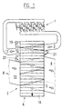
- Such a pressure wave machine is from the prior art Technology known, for example from CH-A-681 738. It is a first general object of the present invention Efficiency of a gas dynamic pressure wave machine according to State of the art, as shown schematically in Figure 1 is shown, by means of various measures improve.
- a pressure wave machine is known from WO 97 33080, which is both a three way catalyst and one Has oxidation catalyst and wherein between Exhaust of the engine and the three-way catalyst one Heating device is arranged.
- the invention is based on the number of pressure wave cycles independently; it can be used for pressure wave machines with only one Cycle or with two or more cycles.
- Figure 1 shows a development of the rotor Pressure wave machine, and you can see that Internal combustion engine 1, the gas dynamic Pressure wave machine 2, the high pressure exhaust duct 3 and Low-pressure exhaust duct 4 including the purge air S, the rotor 6 with the individual cells 18, the fresh air inlet 8, or low-pressure fresh air supply duct 14, the high-pressure charge air duct 10, which merges into the charge air duct 11 and leads to the internal combustion engine 1.
- the pressure wave machine is known with Methods, for example characteristic methods and Design calculations based on those from the combustion engine manufacturer desired point, usually at the nominal speed of the Motors, optimally designed, either without pockets or with one or two or all three pockets can happen.
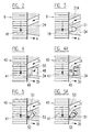
- Figures 2 to 5 relate to influencing the High pressure exhaust flow.
- Figure 2 is based on Figure 1, a high-pressure exhaust duct shown that none Means for influencing the high pressure exhaust gas flow having.
- the rotor 6 with its cells 18 is in developed developed form, and you can also see that Gas housing 24, the high pressure exhaust duct 3 and the Low pressure exhaust duct 4.
- the gas bag is in addition to these elements 21, as shown for example in the beginning CH-A-681 738 mentioned.
- This gas bag as well especially the necessarily existing web 21A between High pressure exhaust duct and gas pocket creates additional ones Losses, especially when low to medium Speeds, temperatures and throughputs of the Blowing off an internal combustion engine is normally unnecessary.
- the unwound rotor 40 is included cells 41 and, in contrast to the gas pocket in Figure 3, a recess 48 is provided in the gas housing 34, the can be changed by a slider 49, like this is indicated by the arrow 50.
- the Slider 49 In Figure 4A the Slider 49 fully engaged in the direction of the arrow so that the High pressure exhaust duct is widened without a web arose.
- the slider can be moved in this way that the high pressure channel is widened so much until the pressure in it has dropped so far that the through the pressure wave process generated boost pressure to the desired Level drops.
- Figures 5 and 5A is a variant of the slide shown, which is a pivotable part 51st acts, which is hinged to a hinge 52 and by control electronics similar to those above can be moved, which causes a widening 53 of the high-pressure exhaust duct.
- the rinsing process is carried out by this device with an enlarged high-pressure exhaust duct through the branch strong from high pressure exhaust gas to low pressure process improved and thus the efficiency increased significantly.
- This procedure can also be used as a gasoline engine Power control can be used by boost pressure through suitable, known measures in the desired Mass is regulated. This measure, i. H. the Enlargement of the high pressure exhaust duct and the avoidance of gas pockets, or the webs in between, causes one significant increase in efficiency.
- the pressure wave machine 30 is over the high pressure exhaust duct 31 and over the high pressure charge air duct 32 with the internal combustion engine 60, for example, an Otto engine. Also shows the pressure wave machine the two low pressure channels 35 and 38 on, and you can see the air inlet 8 and the air filter 9, the charge air cooler 12, a throttle valve 61 and the Motor drive 43.
- a heater 64 To improve the cold start is between the outlet of the internal combustion engine and the high-pressure exhaust duct 31 of the Pressure wave machine built a heater 64, the is designed as a burner and a fuel supply 65 and includes an air supply 66. At 67 is a temperature sensor designated.
- a regulated three-way catalyst 62 with the Lambda probe 63 is arranged, and the heater 64 between the catalyst 62 and the pressure wave machine arranged, thus acts on both the catalyst and on the pressure wave machine and improved on both Aggregates the cold start properties.
- To achieve effective exhaust gas cleaning is between Low pressure exhaust duct and the exhaust 68 another Catalyst, an oxidation catalyst 69 installed.
- the heater already brings one Pressure wave machine, which otherwise according to the prior art a progress, but especially with one Pressure wave machine with high-pressure exhaust duct widening, and with none, one or two catalysts.
Landscapes
- Engineering & Computer Science (AREA)
- Chemical & Material Sciences (AREA)
- Mechanical Engineering (AREA)
- General Engineering & Computer Science (AREA)
- Combustion & Propulsion (AREA)
- Chemical Kinetics & Catalysis (AREA)
- Health & Medical Sciences (AREA)
- Toxicology (AREA)
- Supercharger (AREA)
- Exhaust Gas After Treatment (AREA)
- Mechanical Treatment Of Semiconductor (AREA)
Description
- Figur 1
- zeigt schematisch einen abgewickelten zylindrischen Schnitt durch die Zellen eines Rotors einer Druckwellenmaschine gemäss Stand der Technik,
- Figur 2
- zeigt schematisch ein Detail eines abgewickelten zylindrischen Schnittes durch die Zellen eines Rotors einer Druckwellenmaschine gemäss Stand der Technik,
- Figur 3
- zeigt schematisch ein Detail eines abgewickelten zylindrischen Schnittes durch die Zellen eines Rotors einer weiteren Druckwellenmaschine gemäss Stand der Technik,
- Figuren 4, 4A
- zeigen schematisch ein Detail eines abgewickelten zylindrischen Schnittes durch die Zellen eines Rotors einer Druckwellenmaschine gemäss Erfindung,
- Figuren 5, 5A
- zeigen eine Variante zu der Ausführung nach den Figuren 4, 4A, und
- Figur 6
- zeigt schematisch eine Druckwellenmaschine mit Heizeinrichtung und Katalysatoren.
Claims (8)
- Gasdynamische Druckwellenmaschine, die bestimmt ist, einer Verbrennungsmaschine Ladeluft zuzuführen, mit einem Zellen (18, 41) aufweisenden Rotor (6, 40), einem Niederdruck-Frischluftzufuhrkanal (14, 38), einem zur Verbrennungsmaschine (1, 33) führenden Hochdruck-Ladeluftkanal (10, 32), einem von der Verbrennungsmaschine herkommenden Hochdruck-Abgaskanal (3, 31) und einem Niederdruck-Abgaskanal (4, 35), wobei der Niederdruck-Abgaskanal (4, 35) und der Hochdruck-Abgaskanal (3, 31) in einem Gasgehäuse (5, 34) und der Niederdruck-Frischluftzufuhrkanal (14, 38) und der Hochdruck-Ladeluftkanal (10, 32) in einem Luftgehäuse (15, 39) angeordnet sind, dadurch gekennzeichnet, dass der Hochdruck-Abgaskanal (31) rotorseitig verbreitert ist und Mittel (49, 51) aufweist, ohne Bildung eines Steges diese Verbreiterung (48, 53) zu verändern.
- Gasdynamische Druckwellenmaschine nach Anspruch 1, dadurch gekennzeichnet, dass die Mittel einen gesteuerten Schieber (49) enthalten.
- Gasdynamische Druckwellenmaschine nach Anspruch 1, dadurch gekennzeichnet, dass die Mittel einen Schwenkschieber (51) enthalten.
- Gasdynamische Druckwellenmaschine nach einem der Ansprüche 1 bis 3, dadurch gekennzeichnet, dass zwischen dem Auslass der Verbrennungsmaschine (60) und dem Hochdruck-Abgaskanal (31) eine Heizeinrichtung (64) angeordnet ist.
- Gasdynamische Druckwellenmaschine nach Anspruch 4, dadurch gekennzeichnet, dass die Heizeinrichtung ein Brenner (64) mit Luft- und Brennstoffzufuhr (66, 65) oder eine elektrische Heizeinrichtung ist.
- Gasdynamische Druckwellenmaschine nach einem der Ansprüche 1 bis 5, die an einen Otto-Motor angeschlossen ist, dadurch gekennzeichnet, dass zwischen dem Auslass des Motors (60) und dem Hochdruck-Abgaskanal (31) der Druckwellenmaschine ein Dreiwegkatalysator (62) angeordnet ist.
- Gasdynamische Druckwellenmaschine nach Anspruch 6, dadurch gekennzeichnet, dass zwischen dem Niederdruck-Abgaskanal (35) und dem Auslass (68) der Druckwellenmaschine ein Oxydations-Katalysator (69) nachgeschaltet ist.
- Gasdynamische Druckwellenmaschine nach Anspruch 6 oder 7, dadurch gekennzeichnet, dass die Heizeinrichtung (64) zwischen dem Dreiweg-Katalysator (62) und dem Hochdruck-Abgaskanal (31) der Druckwellenmaschine angeordnet ist.
Priority Applications (9)
| Application Number | Priority Date | Filing Date | Title |
|---|---|---|---|
| ES97810615T ES2210485T3 (es) | 1997-08-29 | 1997-08-29 | Maquina de onda de compresion dinamica de gas. |
| EP97810615A EP0899435B1 (de) | 1997-08-29 | 1997-08-29 | Gasdynamische Druckwellenmaschine |
| AT97810615T ATE254718T1 (de) | 1997-08-29 | 1997-08-29 | Gasdynamische druckwellenmaschine |
| DE59711033T DE59711033D1 (de) | 1997-08-29 | 1997-08-29 | Gasdynamische Druckwellenmaschine |
| JP2000508893A JP4190725B2 (ja) | 1997-08-29 | 1998-08-25 | 気体力学的圧力波機械 |
| KR1020007002047A KR20010023405A (ko) | 1997-08-29 | 1998-08-25 | 가스-동압력 파형기 |
| AU93465/98A AU744674B2 (en) | 1997-08-29 | 1998-08-25 | Gas-dynamic pressure-wave machine |
| US09/486,288 US6367460B1 (en) | 1997-08-29 | 1998-08-25 | Gas-dynamic pressure wave machine |
| PCT/EP1998/005378 WO1999011914A1 (de) | 1997-08-29 | 1998-08-25 | Gasdynamische druckwellenmaschine |
Applications Claiming Priority (1)
| Application Number | Priority Date | Filing Date | Title |
|---|---|---|---|
| EP97810615A EP0899435B1 (de) | 1997-08-29 | 1997-08-29 | Gasdynamische Druckwellenmaschine |
Publications (2)
| Publication Number | Publication Date |
|---|---|
| EP0899435A1 EP0899435A1 (de) | 1999-03-03 |
| EP0899435B1 true EP0899435B1 (de) | 2003-11-19 |
Family
ID=8230360
Family Applications (1)
| Application Number | Title | Priority Date | Filing Date |
|---|---|---|---|
| EP97810615A Expired - Lifetime EP0899435B1 (de) | 1997-08-29 | 1997-08-29 | Gasdynamische Druckwellenmaschine |
Country Status (9)
| Country | Link |
|---|---|
| US (1) | US6367460B1 (de) |
| EP (1) | EP0899435B1 (de) |
| JP (1) | JP4190725B2 (de) |
| KR (1) | KR20010023405A (de) |
| AT (1) | ATE254718T1 (de) |
| AU (1) | AU744674B2 (de) |
| DE (1) | DE59711033D1 (de) |
| ES (1) | ES2210485T3 (de) |
| WO (1) | WO1999011914A1 (de) |
Families Citing this family (6)
| Publication number | Priority date | Publication date | Assignee | Title |
|---|---|---|---|---|
| DE50204848D1 (de) | 2002-03-18 | 2005-12-15 | Swissauto Eng Sa | Gasdynamische Druckwellenmaschine |
| DE50204469D1 (de) * | 2002-06-28 | 2006-02-16 | Swissauto Eng Sa | Verfahren zur Regelung einer Verbrennungsmaschine mit einer gasdynamischen Druckwellenmaschine |
| FR2905980B1 (fr) * | 2006-09-20 | 2008-11-07 | Renault Sas | "groupe motopropulseur, en particulier pour vehicule automobile, ainsi que circuit et procede de suralimentation de son moteur" |
| DE102010054505B4 (de) * | 2010-12-14 | 2014-06-12 | Benteler Automobiltechnik Gmbh | Druckwellenladeranordnung und Verfahren zum Betreiben einer Druckwellenladeranordnung |
| DE102011051559B3 (de) * | 2011-07-05 | 2012-08-16 | Benteler Automobiltechnik Gmbh | Verfahren zur Einstellung eines Ladedrucks einer Verbrennungskraftmaschine |
| DE102018214922A1 (de) * | 2018-09-03 | 2020-03-05 | Continental Automotive Gmbh | Abgasanlage |
Family Cites Families (12)
| Publication number | Priority date | Publication date | Assignee | Title |
|---|---|---|---|---|
| ATE5276T1 (de) * | 1980-05-02 | 1983-11-15 | Bbc Aktiengesellschaft Brown, Boveri & Cie. | Steuerungseinrichtung in einer gasdynamischen druckwellenmaschine zur aufladung von verbrennungsmotoren. |
| US4488532A (en) * | 1981-11-30 | 1984-12-18 | Bbc Brown, Boveri & Company, Limited | Gas-dynamic pressure wave machine with exhaust gas bypass |
| ATE16626T1 (de) * | 1982-06-02 | 1985-12-15 | Bbc Brown Boveri & Cie | Verfahren und einrichtung zur steuerung der rezirkulation von abgas in einem druckwellenlader fuer einen verbrennungsmotor. |
| EP0123990B1 (de) * | 1983-05-02 | 1986-12-30 | BBC Brown Boveri AG | Regeleinrichtung eines Druckwellenladers |
| CH666521A5 (de) * | 1985-04-30 | 1988-07-29 | Bbc Brown Boveri & Cie | Druckwellenlader fuer einen verbrennungsmotor mit einer einrichtung zur steuerung des hochdruckabgasstromes. |
| JPS6220630A (ja) * | 1985-07-19 | 1987-01-29 | Mazda Motor Corp | 圧力波過給機付エンジン |
| ATE53891T1 (de) * | 1986-02-28 | 1990-06-15 | Bbc Brown Boveri & Cie | Durch die gaskraefte angetriebener, freilaufender druckwellenlader. |
| JP2552497B2 (ja) * | 1987-08-31 | 1996-11-13 | 正志 原田 | プレッシャーウェーブ・スーパーチャージャー |
| CH681738A5 (de) | 1989-11-16 | 1993-05-14 | Comprex Ag | |
| JPH0481510A (ja) * | 1990-07-20 | 1992-03-16 | Mazda Motor Corp | 圧力波過給機付エンジンの排気装置 |
| AT408785B (de) * | 1995-11-30 | 2002-03-25 | Blank Otto Ing | Aufladeeinrichtung für die ladeluft einer verbrennungskraftmaschine |
| CA2247393C (en) * | 1996-03-05 | 2004-09-07 | Swissauto Engineering S.A. | Spark ignition engine with pressure-wave supercharger |
-
1997
- 1997-08-29 EP EP97810615A patent/EP0899435B1/de not_active Expired - Lifetime
- 1997-08-29 DE DE59711033T patent/DE59711033D1/de not_active Expired - Lifetime
- 1997-08-29 AT AT97810615T patent/ATE254718T1/de not_active IP Right Cessation
- 1997-08-29 ES ES97810615T patent/ES2210485T3/es not_active Expired - Lifetime
-
1998
- 1998-08-25 AU AU93465/98A patent/AU744674B2/en not_active Ceased
- 1998-08-25 KR KR1020007002047A patent/KR20010023405A/ko not_active Withdrawn
- 1998-08-25 WO PCT/EP1998/005378 patent/WO1999011914A1/de not_active Ceased
- 1998-08-25 US US09/486,288 patent/US6367460B1/en not_active Expired - Lifetime
- 1998-08-25 JP JP2000508893A patent/JP4190725B2/ja not_active Expired - Fee Related
Also Published As
| Publication number | Publication date |
|---|---|
| KR20010023405A (ko) | 2001-03-26 |
| AU744674B2 (en) | 2002-02-28 |
| EP0899435A1 (de) | 1999-03-03 |
| DE59711033D1 (de) | 2003-12-24 |
| JP4190725B2 (ja) | 2008-12-03 |
| AU9346598A (en) | 1999-03-22 |
| WO1999011914A1 (de) | 1999-03-11 |
| ES2210485T3 (es) | 2004-07-01 |
| ATE254718T1 (de) | 2003-12-15 |
| US6367460B1 (en) | 2002-04-09 |
| JP2001515171A (ja) | 2001-09-18 |
Similar Documents
| Publication | Publication Date | Title |
|---|---|---|
| DE69801891T2 (de) | Steuervorrichtung für abgasrückführungssystem in einer brennkraftmaschine | |
| DE3710195C2 (de) | ||
| DE10134300C2 (de) | Steuerungsverfahren für einen Dieselmotor mit Abgasnachbehandlungsanordnung und Turbolader | |
| DE69823039T2 (de) | Gasdynamische druckwellenmaschine | |
| DE69909952T2 (de) | Abgasemissionsregeleinrichtung für ein Hybrid-Fahrzeug | |
| DE69520594T2 (de) | Anordnung zur abgasrückführung in aufgeladenen brennkraftmaschinen mit in reihe geschalteten turbinen | |
| EP3475543B1 (de) | Verfahren und vorrichtung zur abgasnachbehandlung eines verbrennungsmotors | |
| DE3532345A1 (de) | Verfahren und einrichtung zum betrieb eines dieselmotors mit abgaspartikelfilter | |
| WO2008125579A1 (de) | Turboaufgeladene brennkraftmaschine und verfahren | |
| EP1936161A2 (de) | Verfahren zum Betrieb einer Brennkraftmaschine | |
| EP1375858B1 (de) | Verfahren zur Regelung einer Verbrennungsmaschine mit einer gasdynamischen Druckwellenmaschine | |
| EP0856645B1 (de) | Verfahren zur Regelung der Temperatur einer Katalysatoranordnung sowie Vorrichtung zur Durchführung des Verfahrens | |
| EP0899435B1 (de) | Gasdynamische Druckwellenmaschine | |
| DE69114490T2 (de) | System zur steuerung der abgas-temperatur eines katalytisch gereinigten verbrennungsmotors. | |
| DE102017202435A1 (de) | Verfahren und Steuergerät zum Steuern des Öffnungszustandes einer Abgasklappe eines Verbrennungsmotors | |
| EP0252316B1 (de) | Brennkraftmaschine mit Druckwellenlader und Lamda-Sonde | |
| EP1347157B1 (de) | Gasdynamische Druckwellenmaschine | |
| DE112007002933T5 (de) | Verfahren zur modulierten Turboladerbremsung | |
| DE102009051027A1 (de) | Antriebsaggregat sowie Verfahren zum Betreiben eines Antriebsaggregats | |
| EP1119695A1 (de) | Verfahren zur regelung oder steuerung einer aufgeladenen brennkraftmaschine | |
| DE102022001473B4 (de) | Verfahren zur simultanen Regelung der Abgastemperatur und des Ladedrucks einer Brennkraftmaschine | |
| WO1999011915A1 (de) | Gasdynamische druckwellenmaschine | |
| EP1375859B1 (de) | Verfahren zur Regelung einer Verbrennungsmaschine mit einer Gasdynamischen Druckwellenmaschine | |
| DE102017127092A1 (de) | Steuerbare Turboladervorrichtung einer Brennkraftmaschine | |
| DE102011055452A1 (de) | Verfahren zur Einstellung eines Ladedruckes einer Verbrennungskraftmaschine |
Legal Events
| Date | Code | Title | Description |
|---|---|---|---|
| PUAI | Public reference made under article 153(3) epc to a published international application that has entered the european phase |
Free format text: ORIGINAL CODE: 0009012 |
|
| AK | Designated contracting states |
Kind code of ref document: A1 Designated state(s): AT CH DE ES FR GB IT LI SE |
|
| AX | Request for extension of the european patent |
Free format text: AL;LT;LV;RO;SI |
|
| 17P | Request for examination filed |
Effective date: 19990901 |
|
| AKX | Designation fees paid |
Free format text: AT CH DE ES FR GB IT LI SE |
|
| 17Q | First examination report despatched |
Effective date: 20010430 |
|
| GRAH | Despatch of communication of intention to grant a patent |
Free format text: ORIGINAL CODE: EPIDOS IGRA |
|
| GRAS | Grant fee paid |
Free format text: ORIGINAL CODE: EPIDOSNIGR3 |
|
| GRAA | (expected) grant |
Free format text: ORIGINAL CODE: 0009210 |
|
| AK | Designated contracting states |
Kind code of ref document: B1 Designated state(s): AT CH DE ES FR GB IT LI SE |
|
| REG | Reference to a national code |
Ref country code: GB Ref legal event code: FG4D Free format text: NOT ENGLISH |
|
| REG | Reference to a national code |
Ref country code: CH Ref legal event code: EP |
|
| REF | Corresponds to: |
Ref document number: 59711033 Country of ref document: DE Date of ref document: 20031224 Kind code of ref document: P |
|
| PG25 | Lapsed in a contracting state [announced via postgrant information from national office to epo] |
Ref country code: SE Free format text: LAPSE BECAUSE OF FAILURE TO SUBMIT A TRANSLATION OF THE DESCRIPTION OR TO PAY THE FEE WITHIN THE PRESCRIBED TIME-LIMIT Effective date: 20040219 |
|
| GBT | Gb: translation of ep patent filed (gb section 77(6)(a)/1977) |
Effective date: 20040211 |
|
| REG | Reference to a national code |
Ref country code: ES Ref legal event code: FG2A Ref document number: 2210485 Country of ref document: ES Kind code of ref document: T3 |
|
| ET | Fr: translation filed | ||
| PG25 | Lapsed in a contracting state [announced via postgrant information from national office to epo] |
Ref country code: AT Free format text: LAPSE BECAUSE OF NON-PAYMENT OF DUE FEES Effective date: 20040829 |
|
| PLBE | No opposition filed within time limit |
Free format text: ORIGINAL CODE: 0009261 |
|
| STAA | Information on the status of an ep patent application or granted ep patent |
Free format text: STATUS: NO OPPOSITION FILED WITHIN TIME LIMIT |
|
| 26N | No opposition filed |
Effective date: 20040820 |
|
| PGFP | Annual fee paid to national office [announced via postgrant information from national office to epo] |
Ref country code: ES Payment date: 20100825 Year of fee payment: 14 Ref country code: CH Payment date: 20100824 Year of fee payment: 14 |
|
| PGFP | Annual fee paid to national office [announced via postgrant information from national office to epo] |
Ref country code: GB Payment date: 20100819 Year of fee payment: 14 |
|
| PGFP | Annual fee paid to national office [announced via postgrant information from national office to epo] |
Ref country code: IT Payment date: 20110823 Year of fee payment: 15 |
|
| REG | Reference to a national code |
Ref country code: CH Ref legal event code: PL |
|
| GBPC | Gb: european patent ceased through non-payment of renewal fee |
Effective date: 20110829 |
|
| PG25 | Lapsed in a contracting state [announced via postgrant information from national office to epo] |
Ref country code: LI Free format text: LAPSE BECAUSE OF NON-PAYMENT OF DUE FEES Effective date: 20110831 Ref country code: CH Free format text: LAPSE BECAUSE OF NON-PAYMENT OF DUE FEES Effective date: 20110831 |
|
| PG25 | Lapsed in a contracting state [announced via postgrant information from national office to epo] |
Ref country code: GB Free format text: LAPSE BECAUSE OF NON-PAYMENT OF DUE FEES Effective date: 20110829 |
|
| REG | Reference to a national code |
Ref country code: ES Ref legal event code: FD2A Effective date: 20121207 |
|
| PG25 | Lapsed in a contracting state [announced via postgrant information from national office to epo] |
Ref country code: ES Free format text: LAPSE BECAUSE OF NON-PAYMENT OF DUE FEES Effective date: 20110830 |
|
| PG25 | Lapsed in a contracting state [announced via postgrant information from national office to epo] |
Ref country code: IT Free format text: LAPSE BECAUSE OF NON-PAYMENT OF DUE FEES Effective date: 20120829 |
|
| REG | Reference to a national code |
Ref country code: FR Ref legal event code: PLFP Year of fee payment: 19 |
|
| PGFP | Annual fee paid to national office [announced via postgrant information from national office to epo] |
Ref country code: DE Payment date: 20150921 Year of fee payment: 19 |
|
| PGFP | Annual fee paid to national office [announced via postgrant information from national office to epo] |
Ref country code: FR Payment date: 20150820 Year of fee payment: 19 |
|
| REG | Reference to a national code |
Ref country code: DE Ref legal event code: R119 Ref document number: 59711033 Country of ref document: DE |
|
| REG | Reference to a national code |
Ref country code: FR Ref legal event code: ST Effective date: 20170428 |
|
| PG25 | Lapsed in a contracting state [announced via postgrant information from national office to epo] |
Ref country code: DE Free format text: LAPSE BECAUSE OF NON-PAYMENT OF DUE FEES Effective date: 20170301 Ref country code: FR Free format text: LAPSE BECAUSE OF NON-PAYMENT OF DUE FEES Effective date: 20160831 |