EP0899136B1 - Luftauslass für ein Kraftfahrzeug - Google Patents
Luftauslass für ein Kraftfahrzeug Download PDFInfo
- Publication number
- EP0899136B1 EP0899136B1 EP19980440171 EP98440171A EP0899136B1 EP 0899136 B1 EP0899136 B1 EP 0899136B1 EP 19980440171 EP19980440171 EP 19980440171 EP 98440171 A EP98440171 A EP 98440171A EP 0899136 B1 EP0899136 B1 EP 0899136B1
- Authority
- EP
- European Patent Office
- Prior art keywords
- control
- cam
- barrel according
- rotation
- fins
- Prior art date
- Legal status (The legal status is an assumption and is not a legal conclusion. Google has not performed a legal analysis and makes no representation as to the accuracy of the status listed.)
- Expired - Lifetime
Links
Images


Classifications
-
- B—PERFORMING OPERATIONS; TRANSPORTING
- B60—VEHICLES IN GENERAL
- B60H—ARRANGEMENTS OF HEATING, COOLING, VENTILATING OR OTHER AIR-TREATING DEVICES SPECIALLY ADAPTED FOR PASSENGER OR GOODS SPACES OF VEHICLES
- B60H1/00—Heating, cooling or ventilating devices
- B60H1/34—Nozzles; Air-diffusers
- B60H1/3414—Nozzles; Air-diffusers with means for adjusting the air stream direction
- B60H1/3421—Nozzles; Air-diffusers with means for adjusting the air stream direction using only pivoting shutters
-
- B—PERFORMING OPERATIONS; TRANSPORTING
- B60—VEHICLES IN GENERAL
- B60H—ARRANGEMENTS OF HEATING, COOLING, VENTILATING OR OTHER AIR-TREATING DEVICES SPECIALLY ADAPTED FOR PASSENGER OR GOODS SPACES OF VEHICLES
- B60H1/00—Heating, cooling or ventilating devices
- B60H1/34—Nozzles; Air-diffusers
- B60H2001/3471—Details of actuators
Definitions
- the present invention relates to an aerator barrel for a motor vehicle comprising a body mounted in the passenger compartment of the vehicle at the outlet of an air duct, at least one set of directional fins for deflecting the air flow, parallel, pivotable and mounted in said body around fixed pivot axes A, connected between them by a connecting bar at connecting points B distant from the axes of pivoting A, and a control wheel mounted in rotation about a fixed axis in said body.
- aerator barrels provided with “curtain” type fins this is ie aligned fins that can completely block the air outlet, have relatively complex fins control means, requiring many rooms.
- One of the means provides that the control wheel engages a pinion satellite mounted on a fixed axis in the body. This sprocket in turn and in direction reverses a drive gear. The rotation of this drive gear causes the pivoting of the fins by means of a cam provided on said pinion and an axis of control provided on the fin link bar.
- the purpose of the present invention is to simplify the design of this type of barrel to reduce the number of parts and the cost price while avoiding disadvantages mentioned above in order to ensure optimum quality of operation fins.
- an aerator barrel as defined in the preamble and characterized in that the connecting bar is arranged in a plane substantially parallel to that defined by the control wheel and in that the control wheel is coupled positively to said connecting bar by at least one control finger integral of one of the parts constituted by the wheel and the bar, and by at least one cam provided on the other part, this control finger being substantially parallel to the axis of rotation of the wheel.
- control finger is integral with the wheel and distant from its axis of rotation by a radius R, and the cam is secured to the connecting bar.
- the control finger can pass through said body by means of a light in arc of a circle whose center coincides with the axis of rotation of the thumb wheel.
- said light extends over an angular sector of angle ⁇ delimiting the rotation of the control wheel between two extreme positions.
- the cam extends over a length at least equal to that traversed by the control finger between the two positions ends of the control wheel so as to control the rotation of the fins between their two extreme positions which correspond to a position of the fins fully closed and a fully open fin position.
- the cam can be a ramp of left shape or a groove of left shape whose section is substantially equal to the diameter of the control finger.
- the cam may include a zone of locking arranged to lock the fins in the closed position.
- the barrel has two cooperating cams respectively with two control fingers, one of the cams being arranged to open the fins and the other to close them.
- control finger is integral with the connecting bar and the cam is integral with the control wheel.
- cam can be a substantially V-shaped groove and have advantageously at its lowest point a hollow and the control finger can have an indexing tooth arranged to ensure continuous movement and in the right direction of the fins when the control wheel is rotated.
- the distance between the fixed pivot axis A and the connection point B can be different for each wing in order to create a fan effect.
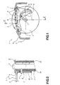
- the aerator barrel 1 comprises a hollow body 2 mounted in the passenger compartment of a vehicle at the outlet of an air duct of the ventilation circuit, a set of directional fins 3 to deflect the air flow interconnected by a connecting strip 4, and a control wheel 5 accessible from the passenger compartment by the user to vary the position of said fins.
- the body 2 of the barrel is closed on the front face by a cover 6 revealing the control wheel 5 and the directional fins 3.
- the directional fins 3 are arranged parallel to each other and mounted in the body 2 in a pivoting manner around fixed pivot axes A. They are arranged to form a "curtain", that is to say that they are aligned so as to completely block the outlet of the air flow in one of their extreme positions represented in FIG. 1. The other extreme position corresponds to their completely open position represented in FIG. 3. These two extreme positions are offset by 'An angle ⁇ 1 to ⁇ 5 different depending on the position of each fin 3, which are for example five in number, this number can vary from 1 to 10 for example. These angles are also shown in Figure 3 where the closed position is shown in broken lines.
- connection bar 4 is interconnected by the connecting bar 4 in connection points B distant from the pivot axes A to create a couple of rotation.
- This connecting bar 4 is controlled by the control wheel 5 which is rotatably mounted in said body 2 around a fixed axis C and between two walls parallels 2a, 2b of said body.
- the connection bar 4 and the control wheel 5 are preferably arranged in two substantially parallel planes.
- control wheel 5 is positively coupled to the connection strip 4 by a control finger 7 secured to the thumb wheel 5 which slides on a cam 8 secured to the connecting bar 4.
- control finger 7 may be integral with the connecting bar 4 and the cam 8 of the control wheel 5.
- the axis D of the control finger 7 is substantially parallel to the axis C of rotation of the control wheel 5 and distant from this axis of a radius R.
- the control finger 7 passes through said body 2 through a groove 9 having an arc shape, center C, radius R and extending over a angular sector ⁇ which can be between 10 ° and 130 °.
- the ends of this groove 9 define the stops for the two extreme positions of the thumbwheel control 7 which correspond to the two extreme positions of the fins directional 3, i.e. a fully open position of the fins and a position of the fully closed fins.
- the cam 8 consists of a groove 10 of left shape provided in an extension of the connecting bar 4.
- This cam 8 can also consist of a ramp of left shape in a variant of production.
- the groove 10 has a section substantially equal to the diameter of the finger control 7 to allow it to slide with slight friction.
- This groove 10 extends over a length at least equal to the path traveled by the finger control 7 between the two extreme positions of the control wheel 5. It has a curved left shape that allows the two positions to correspond extremes of the control wheel 5 to those of the directional fins 3. And between these two extreme positions of the control wheel 5, the control finger 7 occupies in the groove 10 intermediate positions which correspond to the intermediate open positions of the directional fins 3. These open positions intermediaries are stable since the control finger 7 is retained by friction in the groove 10.
- All the parts forming said ventilation barrel 1 can be produced in a injected synthetic material, whether or not using an overmolding process.
- the operation of the aerator barrel 1 according to the invention is very simple.
- the directional fins 3 When the directional fins 3 are in closed position, they prevent the exit of the air flow and play the role of a shutter.
- the air duct can be fitted with an internal shutter controlled by a lever or an independent wheel.
- the opening of the directional fins 3 is obtained by operating the control wheel 5 which directly actuates the link bar 4 via the control finger 7 and the groove 10. Thanks to this connection direct, the rotation of the directional fins 3 has the advantage of being proportional to that of the control wheel 5 over the entire angular travel ⁇ . So, we get better management of the different positions of the directional fins 3 and maneuvering efforts.
- FIGS. 4A and 4B represent a ventilation barrel 11 which constitutes a first alternative embodiment of the ventilation barrel 1 described above. All the pieces identical have the same reference number. Only the cam 18 is different.
- the groove 20 of left shape which constitutes it comprises a locking zone 20 ′ of the fins 3 in closed position. In this locking zone 20 ′, the groove 20 comprises a bend orienting the groove 20 substantially in the direction of the axis C of rotation of the thumb wheel 5.
- the control finger 7 is located in the locking zone 20 'just after the bend.
- the fins 3 are closed and locked in this position.
- FIG. 5 illustrates an aeration barrel 21 which constitutes a second alternative embodiment of the aeration barrel 1 described above. All identical parts have the same reference number.
- the cam 28 is provided in the wheel 25 and consists of a groove 30 in the form of an open V in which the control finger 27 slides integral with the connecting bar 24. At the lowest point of the groove 30 is provided a recess 30 'arranged to receive an indexing tooth 27' provided on the control finger 27.
- Figures 6A to 6F illustrate this same aerator barrel 21 but without the indexing tooth 27 'and the hollow 30'.
- the control wheel 25 causes the opening of the directional fins 3 and vice versa in the direction of arrow F.
- FIG. 6A illustrates the fins 3 in the closed position
- Figures 6B and 6C illustrate the fins 3 in intermediate positions
- FIG. 6D illustrates the fins 3 in the fully open position of the fins.
- the control wheel 25 can perform an angular rotation X without this causing a displacement of the connecting bar 24 and a rotation of the fins 3.
- the angle Y of rotation fins 3 remains the same. There then exists a so-called "dead" stroke regardless of the direction of rotation O or F of the control wheel 25.
- FIG. 6E which corresponds to FIG. 6B, it is possible to manually move the connecting bar 24 from point G to point H (FIG.
- FIG. 7 illustrates an aeration barrel 31 which constitutes a third alternative embodiment of the aeration barrel 1 described above. All identical parts have the same reference number.
- the connecting bar 34 comprises two cams 38a and 38b located on either side of the axis C of rotation of the control wheel 5.
- Each cam 38a, 38b cooperates with a control finger 37a and 37b provided on the wheel 5.
- the fingers 37a, 37b are diametrically opposite with respect to the axis C of rotation of the control wheel 5 and spaced from this axis of the radius R.
- the control finger 37a acts on the cam 38a in the direction of the arrow K for the opening of the fins 3, in the opposite direction to the arrow F
- the control finger 37b acts on the cam 38b in the direction of the arrow L for the closing of said fins 3, in the direction of arrow F.
- the two cams 38a, 38b therefore have different left shapes to optimize the movement of the fins 3.
- the connecting bar 34 has, in this variant embodiment, a larger surface area than in the embodiments described more high and bra s of connection 34 ', 34 "to the upper fins 3 are very elongated and have great flexibility.
- This alternative embodiment is generally used for large strokes between the opening and closing of the fins in order to control the direction of rotation of the fins.
- the link bar because of its length tends to brace, allowing the rotation of the fins in the opposite direction. With the double cam, this drawback is eliminated.
- FIG. 8 illustrates a ventilation barrel 41 which constitutes a fourth variant of realization of the ventilation barrel 1 described above.
- the fins 3 are represented in the body 2 of the barrel.
- the distance between the points of pivoting A and B is different for each fin 3.
- the radii are not identical, for a displacement of the connecting bar (not shown), a displacement is obtained different angle for each fin 3 and therefore an opening angle between each different fin.
- This alternative embodiment can be applied to each embodiment described above and, in particular, to that illustrated in FIG. 7 taking into account the flexibility of the connecting bar.
- the present invention is not limited to the embodiments described but extends any modification and variant obvious to a person skilled in the art.
- shape of the connecting bars and that of the cams are not limited.
- the angles of maneuvering and moving the different parts can also be varied according to needs.
- the direct connection between the control wheel and the connecting bar can be applied to different types and shapes of barrel aerator.
Landscapes
- Physics & Mathematics (AREA)
- Thermal Sciences (AREA)
- Engineering & Computer Science (AREA)
- Mechanical Engineering (AREA)
- Air-Flow Control Members (AREA)
- Air-Conditioning For Vehicles (AREA)
Claims (12)
- Luftverteiler (1,21,31,41) für ein Kraftfahrzeug, mit einem in dem Karosseriegehäuse des Kraftfahrzeuges an dem Auslaß eines Luftkanals montierten Körper (2), mit mindestens einem Satz von Leitrippen (3) zum Ablenken des Luftflusses, die in dem Körper parallel, schwenkbar und um feste Schwenkachsen A herum angebracht sind, wobei sie durch einen Verbindungssteg (4,24,34) an von den Schwenkachsen A entfernten Verbindungspunkten B miteinander verbunden sind, und mit einem in dem Körper um eine feste Achse C drehbar angebrachten Bedienungsrädchen (5,25), dadurch gekennzeichnet, daß der Verbindungssteg (4,24,34) in einer Ebene angebracht ist, die nahezu parallel zu der durch das Bedienungsrädchen (5,25) definierten verläuft, und daß das Bedienungsrädchen (5,25) mit dem Verbindungssteg (4,24,34) mittels mindestens einem Betätigungszapfen (7,27,37a,37b) positiv und direkt verbunden ist, der mit einem der aus dem Rädchen und dem Steg bestehenden Stücken und mittels mindestens einem auf dem anderen Stück vorgesehenen Nocken (8,18,28,38a,38b) einstückig verbunden ist, wobei die Betätigungsachse praktisch parallel zu der Drehachse C des Rädchens verläuft.
- Verteiler nach Anspruch 1, dadurch gekennzeichnet, daß der Betätigungszapfen (7,37a,37b) mit dem Bedienungsrädchen (5) einstückig verbunden und von dessen Drehachse C mit einem Radius R entfernt ist, und daß der Nocken (8,18,38a,38b) mit dem Verbindungssteg (4,34) einstückig verbunden ist.
- Verteiler nach Anspruch 2, dadurch gekennzeichnet, daß der Betätigungszapfen (7,37a,37b) den Körper (2) mittels eines kreisbogenförmigen Schlitzloches (9) durchquert, dessen Mittelpunkt mit der Drehachse C des Rädchens (5) zusammenfällt.
- Verteiler nach Anspruch 3, dadurch gekennzeichnet, daß sich das Schlitzloch (9) über einen Winkelbereich α erstreckt und die Drehung des Bedienungsrädchens (5) zwischen zwei Endpositionen begrenzt.
- Verteiler nach einem beliebigen der vorangegangenen Ansprüche, dadurch gekennzeichnet, daß sich der Nocken (8,38a,38b) über eine Länge erstreckt, die mindestens gleich derjenigen ist, die von dem Betätigungszapfen (7,37a,37b) zwischen den zwei Endpositionen des Bedienungsrädchens (5) durchlaufen wird, so daß er die Drehung der Leitrippen (3) zwischen ihren zwei Endpositionen veranlaßt, die einer vollständig geschlossenen Position der Rippen und einer vollständig geöffneten Position der Rippen entspricht.
- Verteiler nach einem beliebigen der vorangegangenen Ansprüche, dadurch gekennzeichnet, daß der Nocken (8,38a,38b) eine Rampe mit gekrümmter Form ist.
- Verteiler nach einem beliebigen der Ansprüche 1 bis 5, dadurch gekennzeichnet, daß der Nocken (8,38a,38b) eine Nut (10,20,40a,40b) mit gekrümmter Form ist, deren Querschnitt praktisch gleich dem Durchmesser des Betätigungszapfens (7,37a,37b) ist.
- Verteiler nach einem beliebigen der vorangegangenen Ansprüche, dadurch gekennzeichnet, daß der Nocken (18) eine Arretierungszone (20') aufweist, die so angeordnet ist, daß sie die Rippen (3) in geschlossener Position arretiert.
- Verteiler nach einem beliebigen der Ansprüche 1 bis 7, dadurch gekennzeichnet, daß er zwei Nocken (38a,38b) aufweist, die jeweils mit den zwei Betätigungszapfen (37a,37b) zusammenwirken, wobei einer der Nocken so angeordnet ist, daß er die Rippen öffnet, und der andere so angeordnet ist, daß er sie schließt.
- Verteiler nach Anspruch 1, dadurch gekennzeichnet, daß der Betätigungszapfen (27) mit dem Verbindungssteg einstückig verbunden ist, und der Nocken (28) mit dem Bedienungsrädchen (25) einstückig verbunden ist.
- Verteiler nach Anspruch 10, dadurch gekennzeichnet, daß der Nocken (28) eine praktisch V-förmige Nut (30) ist, die an ihrem niedrigsten Punkt eine Ausnehmung (30') aufweist, und daß der Betätigungszapfen (27) einen Indexierungszapfen (27') aufweist, der so angeordnet ist, daß er bei Drehung des Bedienungsrädchens (25) die kontinuierliche Verlagerung der Rippen (3) in der richtigen Richtung sicherstellt.
- Verteiler nach einem beliebigen der vorangegangenen Ansprüche, dadurch gekennzeichnet, daß die Distanz zwischen der festen Schwenkachse A und dem Verbindungspunkt B für jede Rippe (3) so unterschiedlich ist, daß eine Fächerwirkung erzielt wird.
Applications Claiming Priority (2)
| Application Number | Priority Date | Filing Date | Title |
|---|---|---|---|
| FR9710113A FR2766765B1 (fr) | 1997-08-04 | 1997-08-04 | Barillet d'aerateur pour un vehicule automobile |
| FR9710113 | 1997-08-04 |
Publications (2)
| Publication Number | Publication Date |
|---|---|
| EP0899136A1 EP0899136A1 (de) | 1999-03-03 |
| EP0899136B1 true EP0899136B1 (de) | 2002-04-10 |
Family
ID=9510111
Family Applications (1)
| Application Number | Title | Priority Date | Filing Date |
|---|---|---|---|
| EP19980440171 Expired - Lifetime EP0899136B1 (de) | 1997-08-04 | 1998-08-04 | Luftauslass für ein Kraftfahrzeug |
Country Status (3)
| Country | Link |
|---|---|
| EP (1) | EP0899136B1 (de) |
| DE (1) | DE69804731T2 (de) |
| FR (1) | FR2766765B1 (de) |
Families Citing this family (12)
| Publication number | Priority date | Publication date | Assignee | Title |
|---|---|---|---|---|
| FR2790426B1 (fr) * | 1999-03-02 | 2001-05-04 | Coutier Moulage Gen Ind | Barillet d'aerateur pour vehicule automobile |
| DE59902037D1 (de) * | 1999-05-18 | 2002-08-22 | Trw Automotive Electron & Comp | Lamellensystem |
| DE19935338A1 (de) * | 1999-07-28 | 2001-02-01 | Volkswagen Ag | Luftausströmer mit Lamellen |
| DE20100740U1 (de) | 2001-01-16 | 2001-05-31 | TRW Automotive Electronics & Components GmbH & Co.KG, 67677 Enkenbach-Alsenborn | Luft-Ausströmer, insbesondere zur Fahrzeugklimatisierung |
| DE60207168T2 (de) * | 2001-09-07 | 2006-08-10 | Nihon Plast Co., Ltd., Fuji | Lüftungsanlage |
| CA2488264A1 (en) * | 2002-06-03 | 2003-12-11 | Vrije Universiteit Brussel | Streptococcus thermophilus strain producing exopolysaccharide |
| DE10244327B4 (de) * | 2002-09-23 | 2011-01-13 | Volkswagen Ag | Belüftungsvorrichtung für ein Fahrzeug, insbesondere für ein Kraftfahrzeug |
| DE10244280B4 (de) * | 2002-09-23 | 2013-05-02 | Volkswagen Ag | Belüftungsvorrichtung für ein Fahrzeug, insbesondere für ein Kraftfahrzeug |
| DE102004004427B4 (de) * | 2004-01-28 | 2009-04-09 | Olho-Technik Oleff & Holtmann Ohg | Ausströmdüse |
| DE102010035079A1 (de) * | 2010-08-21 | 2012-02-23 | Volkswagen Ag | Luftausströmvorrichtung für ein Fahrzeug |
| US9073408B2 (en) | 2012-01-09 | 2015-07-07 | Ford Global Technologies, Llc | Register vane air deflector and method |
| FR3050149B1 (fr) * | 2016-04-18 | 2018-04-06 | Reydel Automotive B.V. | Arrangement d'ailettes mobiles en particulier pour aerateur |
Family Cites Families (4)
| Publication number | Priority date | Publication date | Assignee | Title |
|---|---|---|---|---|
| US5072657A (en) * | 1989-02-28 | 1991-12-17 | Daikyo Co., Ltd. | Blowing louver with swinging fins for air conditioners |
| WO1994000310A1 (de) * | 1992-06-19 | 1994-01-06 | Dr. Franz Schneider Gmbh | Düse für belüftungs- oder klimaanlagen, insbesondere in kraftfahrzeuginnenräumen |
| DE19600205C2 (de) * | 1996-01-04 | 2003-06-26 | Schultz Gmbh Aurora | Luftdüse |
| FR2760694B1 (fr) * | 1997-03-12 | 1999-04-30 | Bourbon Automobile Sa | Bouche pour l'ecoulement d'un fluide |
-
1997
- 1997-08-04 FR FR9710113A patent/FR2766765B1/fr not_active Expired - Fee Related
-
1998
- 1998-08-04 EP EP19980440171 patent/EP0899136B1/de not_active Expired - Lifetime
- 1998-08-04 DE DE1998604731 patent/DE69804731T2/de not_active Expired - Fee Related
Also Published As
| Publication number | Publication date |
|---|---|
| DE69804731T2 (de) | 2002-11-14 |
| FR2766765A1 (fr) | 1999-02-05 |
| FR2766765B1 (fr) | 1999-10-01 |
| EP0899136A1 (de) | 1999-03-03 |
| DE69804731D1 (de) | 2002-05-16 |
Similar Documents
| Publication | Publication Date | Title |
|---|---|---|
| EP0899136B1 (de) | Luftauslass für ein Kraftfahrzeug | |
| EP0986688B1 (de) | Verbesserte gelenkvorrichtung eines an einer kraftfahrzeugkarosserie schwenkbar angeordneten flügels | |
| FR2750186A1 (fr) | Mecanisme de commande d'un organe rotatif au moyen d'une poignee pivotante, et siege equipe d'un tel mecanisme | |
| LU83482A1 (fr) | Dispositif en vue de regler le relevement des visieres de casques et analogues | |
| EP0125976B1 (de) | Klappensystem für Luftstromverteilung einer Klimaanlage für Kraftfahrzeuge | |
| EP1838541B1 (de) | Luftdüse für ein kraftfahrzeug zur montage am ausgang eines in den insassenraum des fahrzeuges führenden entlüftungsrohres und entsprechendes fahrzeug | |
| FR2558280A1 (fr) | Dispositif de commande simultanee de deux pieces oscillantes telles que des volets d'un ensemble de climatisation de vehicule automobile | |
| FR2809349A1 (fr) | Barillet d'aerateur pour vehicule automobile | |
| FR2790426A1 (fr) | Barillet d'aerateur pour vehicule automobile | |
| FR3081384A1 (fr) | Dispositif d'aeration permettant le reglage du flux d'air et vehicule associe | |
| EP1410985A1 (de) | Drehbares Steuerrad | |
| EP0704359B1 (de) | Scheibenwischermechanismus mit nichtkreisförmigem Wischfeld | |
| EP0009457B1 (de) | Verschlussgetriebe für Fenster, Türen od. dgl. | |
| EP0939015B1 (de) | Steuervorrichtung für Kraftfahrzeugfeststellbremse | |
| FR2827815A1 (fr) | Aerateur pour vehicule automobile | |
| FR2822108A1 (fr) | Barillet d'aerateur pour vehicule automobile | |
| FR2768663A1 (fr) | Aerateur notamment pour un vehicule automobile | |
| FR2625543A1 (fr) | Nouveau clapet pour canalisations | |
| EP0641682A1 (de) | Übertragungsteil mit scharnierformenden Materialbrücken | |
| EP1207259A2 (de) | Gelenkvorrichtung eines Öffnungselementes eines Kraftfahrzeuges, insbesondere einer Heckklappe | |
| FR2717213A1 (fr) | Dispositif perfectionné d'articulation d'un ouvrant, notamment d'un hayon arrière de véhicule automobile. | |
| FR2881993A1 (fr) | Aerateur a ailettes pivotantes et a ailettes rotatives pour vehicule, notamment pour automobile | |
| FR2710560A1 (fr) | Aérographe à démultiplication multiple. | |
| FR2596100A1 (fr) | Dispositif de reglage de l'inclinaison de bras retractables pour stores a l'italienne et similaires | |
| EP0919900B1 (de) | Vorrichtung zum koaxialen Verbinden zweier miteinander rotierender Elemente |
Legal Events
| Date | Code | Title | Description |
|---|---|---|---|
| PUAI | Public reference made under article 153(3) epc to a published international application that has entered the european phase |
Free format text: ORIGINAL CODE: 0009012 |
|
| AK | Designated contracting states |
Kind code of ref document: A1 Designated state(s): DE FR IT |
|
| AX | Request for extension of the european patent |
Free format text: AL;LT;LV;MK;RO;SI |
|
| RIN1 | Information on inventor provided before grant (corrected) |
Inventor name: CAODURO, JEAN-PAUL |
|
| 17P | Request for examination filed |
Effective date: 19990830 |
|
| AKX | Designation fees paid |
Free format text: DE FR IT |
|
| GRAG | Despatch of communication of intention to grant |
Free format text: ORIGINAL CODE: EPIDOS AGRA |
|
| 17Q | First examination report despatched |
Effective date: 20010510 |
|
| GRAG | Despatch of communication of intention to grant |
Free format text: ORIGINAL CODE: EPIDOS AGRA |
|
| GRAH | Despatch of communication of intention to grant a patent |
Free format text: ORIGINAL CODE: EPIDOS IGRA |
|
| GRAH | Despatch of communication of intention to grant a patent |
Free format text: ORIGINAL CODE: EPIDOS IGRA |
|
| GRAA | (expected) grant |
Free format text: ORIGINAL CODE: 0009210 |
|
| AK | Designated contracting states |
Kind code of ref document: B1 Designated state(s): DE FR IT |
|
| PG25 | Lapsed in a contracting state [announced via postgrant information from national office to epo] |
Ref country code: IT Free format text: LAPSE BECAUSE OF FAILURE TO SUBMIT A TRANSLATION OF THE DESCRIPTION OR TO PAY THE FEE WITHIN THE PRE;WARNING: LAPSES OF ITALIAN PATENTS WITH EFFECTIVE DATE BEFORE 2007 MAY HAVE OCCURRED AT ANY TIME BEFORE 2007. THE CORRECT EFFECTIVE DATE MAY BE DIFFERENT FROM THE ONE RECORDED.SCRIBED TIME-LIMIT Effective date: 20020410 |
|
| REF | Corresponds to: |
Ref document number: 69804731 Country of ref document: DE Date of ref document: 20020516 |
|
| PLBE | No opposition filed within time limit |
Free format text: ORIGINAL CODE: 0009261 |
|
| STAA | Information on the status of an ep patent application or granted ep patent |
Free format text: STATUS: NO OPPOSITION FILED WITHIN TIME LIMIT |
|
| 26N | No opposition filed |
Effective date: 20030113 |
|
| PGFP | Annual fee paid to national office [announced via postgrant information from national office to epo] |
Ref country code: DE Payment date: 20030820 Year of fee payment: 6 |
|
| PG25 | Lapsed in a contracting state [announced via postgrant information from national office to epo] |
Ref country code: DE Free format text: LAPSE BECAUSE OF NON-PAYMENT OF DUE FEES Effective date: 20050301 |
|
| PGFP | Annual fee paid to national office [announced via postgrant information from national office to epo] |
Ref country code: FR Payment date: 20060731 Year of fee payment: 9 |
|
| REG | Reference to a national code |
Ref country code: FR Ref legal event code: ST Effective date: 20080430 |
|
| PG25 | Lapsed in a contracting state [announced via postgrant information from national office to epo] |
Ref country code: FR Free format text: LAPSE BECAUSE OF NON-PAYMENT OF DUE FEES Effective date: 20070831 |