EP0898806B1 - Trägerkörper für eine elektrische wicklung und verfahren zur herstellung eines glimmschutzes - Google Patents
Trägerkörper für eine elektrische wicklung und verfahren zur herstellung eines glimmschutzes Download PDFInfo
- Publication number
- EP0898806B1 EP0898806B1 EP97923815A EP97923815A EP0898806B1 EP 0898806 B1 EP0898806 B1 EP 0898806B1 EP 97923815 A EP97923815 A EP 97923815A EP 97923815 A EP97923815 A EP 97923815A EP 0898806 B1 EP0898806 B1 EP 0898806B1
- Authority
- EP
- European Patent Office
- Prior art keywords
- coating
- supporting element
- supporting
- winding
- conductor
- Prior art date
- Legal status (The legal status is an assumption and is not a legal conclusion. Google has not performed a legal analysis and makes no representation as to the accuracy of the status listed.)
- Expired - Lifetime
Links
- 238000004804 winding Methods 0.000 title claims abstract description 34
- 238000000034 method Methods 0.000 title claims abstract description 9
- 239000000758 substrate Substances 0.000 title abstract 6
- 239000011248 coating agent Substances 0.000 claims abstract description 49
- 238000000576 coating method Methods 0.000 claims abstract description 49
- 239000004020 conductor Substances 0.000 claims description 55
- 229920001296 polysiloxane Polymers 0.000 claims description 11
- 229920002379 silicone rubber Polymers 0.000 claims description 9
- 239000004945 silicone rubber Substances 0.000 claims description 9
- 239000002966 varnish Substances 0.000 claims description 7
- 239000000126 substance Substances 0.000 claims description 5
- 229920003002 synthetic resin Polymers 0.000 claims description 3
- 239000000057 synthetic resin Substances 0.000 claims description 3
- 238000004132 cross linking Methods 0.000 claims 2
- 239000000463 material Substances 0.000 description 11
- 239000004065 semiconductor Substances 0.000 description 10
- 238000005470 impregnation Methods 0.000 description 9
- 238000009413 insulation Methods 0.000 description 8
- 230000015572 biosynthetic process Effects 0.000 description 4
- 238000005336 cracking Methods 0.000 description 3
- 238000006073 displacement reaction Methods 0.000 description 3
- 230000005684 electric field Effects 0.000 description 3
- 239000000945 filler Substances 0.000 description 3
- 239000004922 lacquer Substances 0.000 description 2
- 238000004519 manufacturing process Methods 0.000 description 2
- 238000002791 soaking Methods 0.000 description 2
- 239000007787 solid Substances 0.000 description 2
- 238000002849 thermal shift Methods 0.000 description 2
- 230000035508 accumulation Effects 0.000 description 1
- 238000009825 accumulation Methods 0.000 description 1
- 239000000654 additive Substances 0.000 description 1
- 230000000996 additive effect Effects 0.000 description 1
- 239000003795 chemical substances by application Substances 0.000 description 1
- 230000001427 coherent effect Effects 0.000 description 1
- 230000001143 conditioned effect Effects 0.000 description 1
- 238000001816 cooling Methods 0.000 description 1
- 230000005489 elastic deformation Effects 0.000 description 1
- 238000009434 installation Methods 0.000 description 1
- 239000007788 liquid Substances 0.000 description 1
- 239000010445 mica Substances 0.000 description 1
- 229910052618 mica group Inorganic materials 0.000 description 1
- 229920005989 resin Polymers 0.000 description 1
- 239000011347 resin Substances 0.000 description 1
- 238000000926 separation method Methods 0.000 description 1
- 238000004078 waterproofing Methods 0.000 description 1
Images


Classifications
-
- H—ELECTRICITY
- H02—GENERATION; CONVERSION OR DISTRIBUTION OF ELECTRIC POWER
- H02K—DYNAMO-ELECTRIC MACHINES
- H02K3/00—Details of windings
- H02K3/32—Windings characterised by the shape, form or construction of the insulation
- H02K3/34—Windings characterised by the shape, form or construction of the insulation between conductors or between conductor and core, e.g. slot insulation
-
- H—ELECTRICITY
- H02—GENERATION; CONVERSION OR DISTRIBUTION OF ELECTRIC POWER
- H02K—DYNAMO-ELECTRIC MACHINES
- H02K3/00—Details of windings
- H02K3/32—Windings characterised by the shape, form or construction of the insulation
- H02K3/40—Windings characterised by the shape, form or construction of the insulation for high voltage, e.g. affording protection against corona discharges
-
- H—ELECTRICITY
- H02—GENERATION; CONVERSION OR DISTRIBUTION OF ELECTRIC POWER
- H02K—DYNAMO-ELECTRIC MACHINES
- H02K3/00—Details of windings
- H02K3/32—Windings characterised by the shape, form or construction of the insulation
- H02K3/34—Windings characterised by the shape, form or construction of the insulation between conductors or between conductor and core, e.g. slot insulation
- H02K3/345—Windings characterised by the shape, form or construction of the insulation between conductors or between conductor and core, e.g. slot insulation between conductor and core, e.g. slot insulation
Definitions
- the invention relates to a support body for an electrical Winding and a method for producing a Glow protection for an electrical winding.
- DE-A-3 636 008 discloses a carrier body for an electrical winding in accordance with the preamble of claim 1.
- a conductor winding arrangement is known from EP 0 481 984 B1 for a large electrical machine, in particular for one Turbogenerator.
- the conductor winding arrangement is like this constructed that grooves are provided in a carrier body, in which electrical conductors are arranged.
- the electrical conductors are insulated and with suitable Fixed in the groove.
- the conductor winding arrangement is made from a curable filler in a full soaking process, such as. surrounded by a synthetic resin.
- the first liquid Filler is at a temperature between about 100 and cured at 200 ° C. After curing, the cools now combined into a compact solid body conductor winding arrangement to room temperature. This leads to thermal conditional shrinkage. These lead to tensile stresses within the arrangement.
- the Separation layer is in a range lower or more negligible electric field strength, because between the two, semiconductor layers electrically connected to one another is.
- the two semiconductor layers are almost the same Potential, creating the area between the two semiconductor layers almost potential-free and thus almost field-free. It therefore comes to those concentrated in the area of the separating layer Do not crack to harmful glow discharges.
- the stator winding shown is one with main insulation surrounded electrical conductor in a groove Arranged laminated core.
- the groove has a groove wall.
- the main insulation is made from a first smoldering covering surrounded by semiconducting material.
- a second glow protection coating is applied on this first glow protection covering .
- the second glow-protection coating lies against the groove wall. He is like that treated that he was an impregnating resin in which the stator winding is completely soaked, rejects. With it sticks second glow protection covering neither with the first glow protection covering still with the groove wall. Thermal expansion between electrical conductor and laminated core are thus largely possible without mechanical tension. Thus, crack formation, where glow discharges can occur, largely prevented.
- the object of the invention is a support body for a specify electrical winding.
- Another object of the invention is a process for making a smoldering protection for to specify an electrical winding.
- a carrier body Object achieved by a support body of a support surface has an electrical conductor of an electrical Winding is attachable, which electrical winding from one Impregnation material can be surrounded, the support surface at least partly with a coating for glow protection is provided.
- Such a carrier body allows one in a simple manner build electrical winding so that there is an effective Smolder protection results.
- the special advantage of a coating the support surface of the support body is that the completion of the electrical conductor for attachment or installation on or in the carrier body is considerably simplified. It is now usually only necessary to use the electrical one Isolate conductors and insulation with a single glow protection layer, e.g. a semiconducting tape, too Mistake. Additional measures to prevent crack formation or for controlled cracking for completion of the electrical conductor are unnecessary. This means one significant time and cost savings.
- the coating is preferably such that at most one slight sticking of the coating and the impregnation material is accessible. This is education of cracks reduced by mechanical stresses can result. Such mechanical stresses will in particular due to different thermal expansions caused by electrical conductor and carrier body. A improved smolder protection is achieved in that between the carrier body and the electrical conductor in one Impregnation with the impregnation material through the coating only minor liability results. Mechanical stresses due to a different thermal expansion of the carrier body and electrical conductor through a firm bond between carrier body and electrical conductor could be prevented. With that form no or few cracks over which there is a glow discharge could come.
- the coating is preferably electrically weakly conductive. This supports smoldering protection in that local charge accumulations and thus local, high electrical fields do not occur. The poor conductivity ensures that no significant eddy currents are induced.
- the coating is preferably elastically deformable in such a way that one, especially by different thermal expansion of the electrical conductor and the carrier body, more elucidable Space between the carrier surface and electrical Conductor can be filled through the coating.
- the elastic deformation ensures that a thermal shrinkage of the electrical conductor and / or the support body does not form a gap over which it closes a glow discharge. Due to the elastically deformable Coating is compensated for by shrinkage, that the coating increases its thickness so that no gap forms.
- the coating preferably contains silicone. More preferred is the coating a silicone rubber or a Silicone lacquer, especially one that crosslinks at room temperature Silicone rubber or silicone varnish. Silicone varnish or silicone rubber is a particularly suitable material for the coating.
- the coating can also contain other substances, preferably an additive effecting semiconductor capability, contain.
- the coating is preferably between 10 ⁇ m and 1 mm thick.
- the carrier body is preferably a laminated core for one Stator winding of a generator executed, in particular for a turbogenerator with an output greater than 10 MVA.
- the carrier body in a turbogenerator is further preferred installed, especially in a turbogenerator with a Power greater than 10 MVA, with the turbo generator Has stator winding with a stator current conductor and wherein the electrical winding the stator winding and the electrical Conductor is the stator current conductor.
- the carrier body preferably has a surface, in which a groove is provided with a groove wall, wherein the support surface is formed by the groove wall. More preferred the carrier body has a cover strip through which the groove can be closed, this cover strip has an inside facing the groove, which with the Coating is at least partially provided. Usually becomes an electrical conductor in the groove of the carrier body inserted and secured by the cover strip, which one Displacement of the conductor in the radial direction is prevented. Mechanical stresses caused by a thermal Shift between electrical conductor and cover strip can be caused can be prevented by the fact that the Apply the coating on the inside of the cover strip is.
- the carrier body preferably has an intermediate slide an intermediate slide surface through which the groove in its height is divided into two parts, the intermediate slide surface with the coating at least partially is provided.
- an intermediate slide an intermediate slide surface through which the groove in its height is divided into two parts, the intermediate slide surface with the coating at least partially is provided.
- two electrical conductors are arranged one above the other in a groove become.
- First the lower conductor is installed and against radial displacement by the intermediate slide secured.
- the second is over the intermediate slide electrical conductor installed. Mechanical stresses due to a thermal shift between electrical Ladder and intermediate slide can be caused are prevented by the fact that the intermediate slide surface or part of the intermediate slide surface with the coating is provided.
- a smoldering protection for an electrical winding which one Carrier body with a support surface comprises, directed Object achieved in that an electrical on the support surface Conductor is arranged, the electrical conductor and the carrier body with an impregnating material, in particular a synthetic resin, at least partially surrounded and where the carrier surface in a coating area with a coating is provided, which at most slightly on the Impregnating agent adheres.
- the coating is preferably electrically weakly conductive executed.
- the coating is further preferred as silicone rubber or as a silicone lacquer, in particular as a Room temperature curing silicone rubber or silicone varnish, executed.
- FIG. 1 schematically shows a laminated core 1 for a stator winding a carrier body 1 of a turbogenerator shown. It represents one directed along an axis 1A Hollow cylinder and has an inside 1B and an outside 1C on. Inside 1B and outside 1C are part of one Carrier body surface 1D. Extend on the inside 1B along the axis 1A over the entire length of the support body 1 a plurality of equally spaced grooves 8 with one respective rectangular cross section.
- a turbogenerator becomes an electrical conductor 3 (see FIG. 3) or two electrical conductors 3A one above the other, 3B inserted. The electrical conductors 3 become together an electrical winding, not shown, connected.
- the completed electrical winding not shown together with the carrier body 1 in a full soaking process surrounded by a waterproofing material.
- the impregnation material is hardened. After the impregnation material has hardened a compact, coherent solid.
- FIG. 2 shows a section of the carrier body 1 from FIG 1 a groove 8. It has groove walls 8A, 8B and 8C. This Groove walls 8A, 8B, 8C are part of the support surface 2. On the A wall 4 is applied to the groove wall 8A. This coating 4 is electrically weakly conductive and in one Elastic deformable in the direction normal to surface 8A.
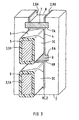
- Figure 3 shows a section corresponding to Figure 2 two electrical conductors arranged one above the other in the groove 8 3A, 3B.
- Each electrical conductor 3A, 3B is of one surrounding insulation 5.
- the lower Conductor 3A is up against a radial shift by an intermediate slide 9 with an intermediate slide surface 9A, 9B secured.
- the upper conductor 3B follows. This in turn will secured against radial displacement upwards by a Cover strip 7 with an inside 7A.
- the support surface In this embodiment, 2 is formed by the inside 7a of the cover strip 7, the intermediate slide surface 9A, 9B of the intermediate slide 9 and through the groove walls 8A, 8B and 8C.
- Figure 4 shows the contact area between electrical Conductor 3 and carrier body 1 in a section of a cross section perpendicular to the electrical conductor 3.
- a heated Condition especially when the impregnation material has hardened, the coating 4 between the external glow protection 6 of the electrical conductor surrounded by the insulation 5 3 and the groove wall 8b of the groove 8 in the carrier body 1 compressed.
- the impregnation material has hardened there is a cooling and thus a thermal Shrinkage of both the electrical conductor 3 and also of the carrier body 1.
- FIG. 5 There is a larger distance between the electrical conductor 3 and the carrier body 1 compared to heated state in Figure 4.
Landscapes
- Engineering & Computer Science (AREA)
- Power Engineering (AREA)
- Insulation, Fastening Of Motor, Generator Windings (AREA)
- Electrical Discharge Machining, Electrochemical Machining, And Combined Machining (AREA)
- Non-Insulated Conductors (AREA)
- Inorganic Insulating Materials (AREA)
- Insulating Bodies (AREA)
- Addition Polymer Or Copolymer, Post-Treatments, Or Chemical Modifications (AREA)
- Processes Specially Adapted For Manufacturing Cables (AREA)
- Manufacturing Of Electric Cables (AREA)
- Emergency Protection Circuit Devices (AREA)
- Resistance Heating (AREA)
Description
- FIG 1
- einen Trägerkörper,
- FIG 2
- einen Ausschnitt aus dem Trägerkörper aus Figur 1,
- FIG 3
- die Nut eines Trägerkörpers mit eingebauten elektrischen Leitern,
- FIG 4
- einen Ausschnitt eines Querschnitts eines an eine Nutwand grenzenden elektrischen Leiters, und
- FIG 5
- wie Figur 4, aber nach thermischer Schrumpfung.
Claims (15)
- Trägerkörper (1) der eine Trägerfläche (2) aufweist, an der ein elektrischer Leiter (3) einer elektrischen Wicklung (3C) anfügbar ist, welche elektrische Wicklung (3C) von einem Imprägnierstoff umgebbar ist,
dadurch gekennzeichnet, daß die Trägerfläche (2) zumindest teilweise mit einer Beschichtung (4) für einen Glimmschutz versehen ist. - Trägerkörper (1) nach Anspruch 1,
dadurch gekennzeichnet, daß die Beschichtung (4) so beschaffen ist, daß ein allenfalls geringfügiges Aneinanderhaften von der Beschichtung (4) und dem Imprägnierstoff erreichbar ist. - Trägerkörper (1) nach Anspruch 1,
dadurch gekennzeichnet, daß die Beschichtung (4) elektrisch schwach leitend ist. - Trägerkörper (1) nach einem der vorhergehenden Ansprüche,
dadurch gekennzeichnet, daß die Beschichtung (4) elastisch so deformierbar ist, daß ein, insbesondere durch thermische Ausdehnung, erzeugbarer Zwischenraum zwischen Trägerfläche (2) und elektrischem Leiter (3) durch die Beschichtung (4) ausfüllbar ist. - Trägerkörper (1) nach einem der vorhergehenden Ansprüche,
dadurch gekennzeichnet, daß die Beschichtung (4) Silikon enthält. - Trägerkörper (1) nach Anspruch 5,
dadurch gekennzeichnet, daß die Beschichtung (4) ein Silikonkautschuk oder ein Silikonlack ist, insbesondere ein bei Raumtemperatur vernetzender Silikonkautschuk bzw. Silikonlack. - Trägerkörper (1) nach einem der vorhergehenden Ansprüche,
dadurch gekennzeichnet, daß die Beschichtung (4) zwischen 10 µm und 1 mm dick ist. - Trägerkörper (1) nach einem der vorhergehenden Ansprüche,
gekennzeichnet durch ein Blechpaket (1) für eine Statorwicklung eines Generators, insbesondere eines Turbogenerators mit einer Leistung größer als 10 MVA. - Trägerkörper (1) der in einem Turbogenerator, insbesondere in einem Turbogenerator mit einer Leistung größer als 10 MVA, eingebaut ist, nach einem der vorhergehenden Ansprüche,
dadurch gekennzeichnet, daß der Turbogenerator eine Statorwicklung (3C) mit einem Statorstromleiter (3) aufweist, wobei die elektrische Wicklung (3C) die Statorwicklung (3C) und der elektrische Leiter (3) der Statorstromleiter (3) ist. - Trägerkörper (1) nach einem der vorhergehenden Ansprüche,
gekennzeichnet durch eine Oberfläche (1D), in welcher eine Nut (8) mit einer Nutwand (8A,8B,8C) vorgesehen ist, welche Nutwand (8A, 8B, 8C) die Trägerfläche (2) bildet. - Trägerkörper (1) nach Anspruch 10,
gekennzeichnet durch einen Deckstreifen (7), der die Nut (8) verschließt und eine zur Nut (8) gerichtete Innenseite (7A) aufweist, welche Innenseite (7A) zumindest teilweise mit der Beschichtung (4) versehen ist. - Trägerkörper (1) nach Anspruch 10 oder 11,
gekennzeichnet durch einen Zwischenschieber (9) mit einer Zwischenschieberoberfläche (9A, 9B), durch den die Nut (8) in zwei Teile aufgeteilt ist, wobei die Zwischenschieberoberfläche (9a, 9B) zumindest teilweise mit der Beschichtung (4) versehen ist. - Verfahren zur Herstellung eines Glimmschutzes für eine elektrische Wicklung (3C), welche einen Trägerkörper (1) mit einer Trägerfläche (2) umfaßt, an welcher Trägerfläche (2) ein elektrischer Leiter (3) angeordnet wird, wobei der Trägerkörper (1) und der elektrische Leiter (3) mit einem Imprägnierstoff, insbesondere einem Kunstharz, zumindest teilweise umgeben werden,
dadurch gekennzeichnet, daß die Trägerfläche (2) in einem Beschichtungsbereich (4A) mit einer Beschichtung (4) versehen wird, an der der Imprägnierstoff allenfalls geringfügig haftet. - Verfahren nach Anspruch 13,
dadurch gekennzeichnet, daß die Beschichtung (4) elektrisch schwach leitend ausgeführt wird. - Verfahren nach Anspruch 13 oder 14,
dadurch gekennzeichnet, daß als Beschichtung (4) ein Silikonkautschuk oder ein Silikonlack, insbesondere ein bei Raumtemperatur vernetzender Silikonkautschuk bzw. Silikonlack, aufgebracht wird.
Applications Claiming Priority (3)
| Application Number | Priority Date | Filing Date | Title |
|---|---|---|---|
| DE19619724 | 1996-05-15 | ||
| DE19619724 | 1996-05-15 | ||
| PCT/DE1997/000973 WO1997043818A1 (de) | 1996-05-15 | 1997-05-14 | Trägerkörper für eine elektrische wicklung und verfahren zur herstellung eines glimmschutzes |
Publications (2)
| Publication Number | Publication Date |
|---|---|
| EP0898806A1 EP0898806A1 (de) | 1999-03-03 |
| EP0898806B1 true EP0898806B1 (de) | 1999-10-27 |
Family
ID=7794463
Family Applications (2)
| Application Number | Title | Priority Date | Filing Date |
|---|---|---|---|
| EP97923779A Expired - Lifetime EP0898805B1 (de) | 1996-05-15 | 1997-04-30 | Leiterwicklungsanordnung für eine elektrische grossmaschine |
| EP97923815A Expired - Lifetime EP0898806B1 (de) | 1996-05-15 | 1997-05-14 | Trägerkörper für eine elektrische wicklung und verfahren zur herstellung eines glimmschutzes |
Family Applications Before (1)
| Application Number | Title | Priority Date | Filing Date |
|---|---|---|---|
| EP97923779A Expired - Lifetime EP0898805B1 (de) | 1996-05-15 | 1997-04-30 | Leiterwicklungsanordnung für eine elektrische grossmaschine |
Country Status (9)
| Country | Link |
|---|---|
| EP (2) | EP0898805B1 (de) |
| JP (2) | JP2000510316A (de) |
| KR (1) | KR20000011131A (de) |
| CN (2) | CN1129995C (de) |
| AT (2) | ATE211592T1 (de) |
| DE (2) | DE59706101D1 (de) |
| ES (1) | ES2139460T3 (de) |
| PL (1) | PL189061B1 (de) |
| WO (2) | WO1997043817A1 (de) |
Families Citing this family (18)
| Publication number | Priority date | Publication date | Assignee | Title |
|---|---|---|---|---|
| JP2002535948A (ja) * | 1999-01-18 | 2002-10-22 | シーメンス アクチエンゲゼルシヤフト | 導体、タービン発電機および導体に対するコロナシールド装置の製造方法 |
| DE19944664A1 (de) * | 1999-09-17 | 2001-08-09 | Von Roll Isola Winding Systems | Glimmschutzanordnung und Verfahren zu ihrer Herstellung |
| US6969940B2 (en) * | 2003-07-08 | 2005-11-29 | Baker Hughes Incorporated | High voltage slot liner for electrical motor |
| CN100386947C (zh) * | 2004-01-14 | 2008-05-07 | 东方电机股份有限公司 | 定子线棒涂敷型防晕结构层及其制造工艺 |
| CN100426630C (zh) * | 2006-08-31 | 2008-10-15 | 施之英 | 定子线圈主绝缘层与防晕层间缠vpi防晕阻隔层的方法 |
| CN101951087A (zh) * | 2010-09-15 | 2011-01-19 | 杨存高 | 高压电机定子线圈对地绝缘层制作方法及高压电机定子线圈和高压电机 |
| EP2587638A1 (de) * | 2011-10-26 | 2013-05-01 | Siemens Aktiengesellschaft | Außenglimmschutz für eine elektrische Maschine |
| EP2645373A1 (de) | 2012-03-26 | 2013-10-02 | Siemens Aktiengesellschaft | Material für Isolationssystem, Isolationssystem, Außenglimmschutz und eine elektrische Maschine |
| EP2645374A1 (de) | 2012-03-26 | 2013-10-02 | Siemens Aktiengesellschaft | Zweilagiges Hochspannungsisolationssystem und elektrische Maschine |
| EP2822153B8 (de) * | 2013-07-03 | 2017-07-26 | GE Renewable Technologies | Koronaentladungsschutz der Wickelköpfe in einer Elektromaschine |
| DE102014208857A1 (de) | 2014-05-12 | 2015-11-12 | Siemens Aktiengesellschaft | Glimmschutzsystem für eine Hochspannungsmaschine, Reparaturlack und Herstellungsverfahren |
| EP3001543A1 (de) * | 2014-09-29 | 2016-03-30 | Siemens Aktiengesellschaft | Aktivteil, Rotor, Stator, elektrische Maschine und Verfahren zur Herstellung eines solchen Aktivteils |
| CN104682598A (zh) * | 2015-03-24 | 2015-06-03 | 湘潭电机股份有限公司 | 一种交流高压电机定子线圈绕包匝间绝缘结构 |
| EP3240150A1 (de) * | 2016-04-25 | 2017-11-01 | Siemens Aktiengesellschaft | Elektrische maschine sowie verfahren zum auseinanderbauen und herstellen der elektrischen maschine |
| CN108878105B (zh) * | 2017-05-08 | 2021-07-30 | 台达电子工业股份有限公司 | 变压器 |
| CN108878118B (zh) | 2017-05-08 | 2021-06-11 | 台达电子工业股份有限公司 | 变压器 |
| JP7040428B2 (ja) * | 2018-12-03 | 2022-03-23 | トヨタ自動車株式会社 | ステータ |
| CN110601411A (zh) * | 2019-09-19 | 2019-12-20 | 中车株洲电机有限公司 | 一种定子槽部组件及其制造方法 |
Family Cites Families (11)
| Publication number | Priority date | Publication date | Assignee | Title |
|---|---|---|---|---|
| US2412851A (en) * | 1945-04-03 | 1946-12-17 | Gen Electric | Dynamoelectric machine and method of making the same |
| GB714311A (en) * | 1951-07-27 | 1954-08-25 | Gen Electric | Improvements relating to high voltage electrical apparatus with slot-embedded conductors |
| CA1016586A (en) * | 1974-02-18 | 1977-08-30 | Canadian General Electric Company Limited | Grounding of outer winding insulation to cores in dynamoelectric machines |
| JPS50151304A (de) * | 1974-05-29 | 1975-12-05 | ||
| GB1568704A (en) * | 1976-04-29 | 1980-06-04 | Ici Ltd | Polyester films |
| JPS56150939A (en) * | 1980-04-24 | 1981-11-21 | Toshiba Corp | Method of insulating iron core of rotary electrical machine and apparatus |
| JPS59117435A (ja) * | 1982-12-22 | 1984-07-06 | Fuji Electric Corp Res & Dev Ltd | 回転電機の高圧コイル |
| JPS59122332A (ja) * | 1982-12-28 | 1984-07-14 | Toshiba Corp | 巻線の固定法 |
| DE3636008A1 (de) * | 1985-12-11 | 1987-06-19 | Bbc Brown Boveri & Cie | Elektrische maschine mit einer in ganztraenktechnik hergestellten statorwicklung |
| JPH02156605A (ja) * | 1988-12-09 | 1990-06-15 | Hitachi Ltd | 電気機器用絶縁線輪 |
| DE4219064A1 (de) * | 1992-06-11 | 1993-12-16 | Asea Brown Boveri | Glimmschutzanordnung für die Statorwicklung einer elektrischen Maschine |
-
1997
- 1997-04-30 EP EP97923779A patent/EP0898805B1/de not_active Expired - Lifetime
- 1997-04-30 DE DE59706101T patent/DE59706101D1/de not_active Expired - Lifetime
- 1997-04-30 WO PCT/DE1997/000894 patent/WO1997043817A1/de not_active Ceased
- 1997-04-30 CN CN97195683A patent/CN1129995C/zh not_active Expired - Fee Related
- 1997-04-30 KR KR1019980709291A patent/KR20000011131A/ko not_active Withdrawn
- 1997-04-30 AT AT97923779T patent/ATE211592T1/de not_active IP Right Cessation
- 1997-04-30 JP JP09540379A patent/JP2000510316A/ja active Pending
- 1997-05-14 DE DE59700634T patent/DE59700634D1/de not_active Expired - Lifetime
- 1997-05-14 CN CN97195848A patent/CN1114983C/zh not_active Expired - Lifetime
- 1997-05-14 ES ES97923815T patent/ES2139460T3/es not_active Expired - Lifetime
- 1997-05-14 JP JP09540396A patent/JP2000510317A/ja active Pending
- 1997-05-14 PL PL97329688A patent/PL189061B1/pl unknown
- 1997-05-14 WO PCT/DE1997/000973 patent/WO1997043818A1/de not_active Ceased
- 1997-05-14 AT AT97923815T patent/ATE186161T1/de not_active IP Right Cessation
- 1997-05-14 EP EP97923815A patent/EP0898806B1/de not_active Expired - Lifetime
Also Published As
| Publication number | Publication date |
|---|---|
| JP2000510316A (ja) | 2000-08-08 |
| ES2139460T3 (es) | 2000-02-01 |
| CN1129995C (zh) | 2003-12-03 |
| CN1223750A (zh) | 1999-07-21 |
| PL329688A1 (en) | 1999-04-12 |
| DE59706101D1 (de) | 2002-02-28 |
| CN1223026A (zh) | 1999-07-14 |
| EP0898806A1 (de) | 1999-03-03 |
| WO1997043818A1 (de) | 1997-11-20 |
| EP0898805B1 (de) | 2002-01-02 |
| PL189061B1 (pl) | 2005-06-30 |
| ATE186161T1 (de) | 1999-11-15 |
| KR20000011131A (ko) | 2000-02-25 |
| JP2000510317A (ja) | 2000-08-08 |
| ATE211592T1 (de) | 2002-01-15 |
| EP0898805A1 (de) | 1999-03-03 |
| WO1997043817A1 (de) | 1997-11-20 |
| DE59700634D1 (de) | 1999-12-02 |
| CN1114983C (zh) | 2003-07-16 |
Similar Documents
| Publication | Publication Date | Title |
|---|---|---|
| EP0481984B1 (de) | Leiterwicklungsanordnung für eine elektrische grossmaschine | |
| EP0368038B2 (de) | Hochspannungsisoliersystem für elektriche Maschinen | |
| WO1997043818A1 (de) | Trägerkörper für eine elektrische wicklung und verfahren zur herstellung eines glimmschutzes | |
| EP0379012B1 (de) | Verfahren zur Herstellung des Stators einer elektrischen Grossmaschine | |
| DE69636892T2 (de) | Hochspannunstrockenspule | |
| DE29880161U1 (de) | Isolierter elektrischer Leiter | |
| WO2012152580A2 (de) | Verfahren zum herstellen eines elektrischen isolationssystems für eine elektrische maschine | |
| EP1060485A1 (de) | Mehrfachparallelleiter für elektrische maschinen und geräte | |
| DE2755050C2 (de) | Verfahren zur Herstellung eines Gitterstabes mit Innenglimmschutz | |
| EP1149457A1 (de) | Elektrischer leiter, turbogenerator und verfahren zur herstellung eines aussenglimmschutzes für einen elektrischen leiter | |
| EP0233538A2 (de) | Elektrischer Kondensator mit Abreisssicherung | |
| EP1995850A1 (de) | Endenglimmschutzanordnung | |
| EP3240150A1 (de) | Elektrische maschine sowie verfahren zum auseinanderbauen und herstellen der elektrischen maschine | |
| EP0839402B1 (de) | Wicklungselement für eine elektrische maschine | |
| WO1998014964A1 (de) | Mehrfachparallelleiter für wicklungen elektrischer maschinen und geräte | |
| DE2126852A1 (de) | Isolierter elektrischer Leiter | |
| DE10323099A1 (de) | Verfahren zum Herstellen einer Wicklung | |
| DE2427474B2 (de) | Metallisches Bauteil für elektrische Maschinen o.dgl. Geräte, insbesondere Transformatoren, und Verfahren zu seiner Herstellung | |
| EP0036911B1 (de) | Stabwicklung mit verdrillten Teilleitern für eine elektrische Maschine mit Nennspannungen grösser als 3,3 kV und Verfahren zur Herstellung der Stabwicklung | |
| DE2126853B2 (de) | Spulen für die Nutenwicklung einer elektrischen Maschine | |
| EP0795225B1 (de) | Verfahren zum herstellen eines mit potentialsteuerungen versehenen wicklungsstabes von hochspannungswicklungen für eine rotierende elektrische maschine | |
| DE102021206120A1 (de) | Verfahren zur Herstellung eines Stators für eine elektrische Maschine, Stator für eine elektrische Maschine und elektrische Maschine | |
| DE102019109517A1 (de) | Wicklung und Verfahren zur Herstellung einer Wicklung | |
| DE19634578A1 (de) | Endenglimmschutzanordnung für die Statorwicklung einer drehenden elektrischen Hochspannungsmaschine | |
| DE102019135528A1 (de) | Primärleiterkabel für ein System zur berührungslosen induktiven Energieübertragung und/oder Datenübertragung |
Legal Events
| Date | Code | Title | Description |
|---|---|---|---|
| PUAI | Public reference made under article 153(3) epc to a published international application that has entered the european phase |
Free format text: ORIGINAL CODE: 0009012 |
|
| 17P | Request for examination filed |
Effective date: 19981105 |
|
| AK | Designated contracting states |
Kind code of ref document: A1 Designated state(s): AT DE ES FR GB NL |
|
| GRAG | Despatch of communication of intention to grant |
Free format text: ORIGINAL CODE: EPIDOS AGRA |
|
| GRAG | Despatch of communication of intention to grant |
Free format text: ORIGINAL CODE: EPIDOS AGRA |
|
| GRAH | Despatch of communication of intention to grant a patent |
Free format text: ORIGINAL CODE: EPIDOS IGRA |
|
| 17Q | First examination report despatched |
Effective date: 19990329 |
|
| GRAH | Despatch of communication of intention to grant a patent |
Free format text: ORIGINAL CODE: EPIDOS IGRA |
|
| GRAA | (expected) grant |
Free format text: ORIGINAL CODE: 0009210 |
|
| AK | Designated contracting states |
Kind code of ref document: B1 Designated state(s): AT DE ES FR GB NL |
|
| REF | Corresponds to: |
Ref document number: 186161 Country of ref document: AT Date of ref document: 19991115 Kind code of ref document: T |
|
| REF | Corresponds to: |
Ref document number: 59700634 Country of ref document: DE Date of ref document: 19991202 |
|
| ET | Fr: translation filed | ||
| GBT | Gb: translation of ep patent filed (gb section 77(6)(a)/1977) |
Effective date: 19991130 |
|
| REG | Reference to a national code |
Ref country code: ES Ref legal event code: FG2A Ref document number: 2139460 Country of ref document: ES Kind code of ref document: T3 |
|
| PLBE | No opposition filed within time limit |
Free format text: ORIGINAL CODE: 0009261 |
|
| STAA | Information on the status of an ep patent application or granted ep patent |
Free format text: STATUS: NO OPPOSITION FILED WITHIN TIME LIMIT |
|
| 26N | No opposition filed | ||
| REG | Reference to a national code |
Ref country code: GB Ref legal event code: IF02 |
|
| PGFP | Annual fee paid to national office [announced via postgrant information from national office to epo] |
Ref country code: AT Payment date: 20020424 Year of fee payment: 6 |
|
| PGFP | Annual fee paid to national office [announced via postgrant information from national office to epo] |
Ref country code: NL Payment date: 20020514 Year of fee payment: 6 |
|
| PGFP | Annual fee paid to national office [announced via postgrant information from national office to epo] |
Ref country code: ES Payment date: 20020523 Year of fee payment: 6 |
|
| PG25 | Lapsed in a contracting state [announced via postgrant information from national office to epo] |
Ref country code: AT Free format text: LAPSE BECAUSE OF NON-PAYMENT OF DUE FEES Effective date: 20030514 |
|
| PG25 | Lapsed in a contracting state [announced via postgrant information from national office to epo] |
Ref country code: ES Free format text: LAPSE BECAUSE OF NON-PAYMENT OF DUE FEES Effective date: 20030516 |
|
| PG25 | Lapsed in a contracting state [announced via postgrant information from national office to epo] |
Ref country code: NL Free format text: LAPSE BECAUSE OF NON-PAYMENT OF DUE FEES Effective date: 20031201 |
|
| NLV4 | Nl: lapsed or anulled due to non-payment of the annual fee |
Effective date: 20031201 |
|
| REG | Reference to a national code |
Ref country code: ES Ref legal event code: FD2A Effective date: 20030516 |
|
| PGFP | Annual fee paid to national office [announced via postgrant information from national office to epo] |
Ref country code: DE Payment date: 20150720 Year of fee payment: 19 |
|
| REG | Reference to a national code |
Ref country code: FR Ref legal event code: PLFP Year of fee payment: 20 |
|
| PGFP | Annual fee paid to national office [announced via postgrant information from national office to epo] |
Ref country code: GB Payment date: 20160512 Year of fee payment: 20 |
|
| PGFP | Annual fee paid to national office [announced via postgrant information from national office to epo] |
Ref country code: FR Payment date: 20160512 Year of fee payment: 20 |
|
| REG | Reference to a national code |
Ref country code: DE Ref legal event code: R119 Ref document number: 59700634 Country of ref document: DE |
|
| PG25 | Lapsed in a contracting state [announced via postgrant information from national office to epo] |
Ref country code: DE Free format text: LAPSE BECAUSE OF NON-PAYMENT OF DUE FEES Effective date: 20161201 |
|
| REG | Reference to a national code |
Ref country code: GB Ref legal event code: PE20 Expiry date: 20170513 |
|
| PG25 | Lapsed in a contracting state [announced via postgrant information from national office to epo] |
Ref country code: GB Free format text: LAPSE BECAUSE OF EXPIRATION OF PROTECTION Effective date: 20170513 |