EP0897699A2 - Prothése dilatable radialement avec contrÔle axial du diamètre - Google Patents
Prothése dilatable radialement avec contrÔle axial du diamètre Download PDFInfo
- Publication number
- EP0897699A2 EP0897699A2 EP98202120A EP98202120A EP0897699A2 EP 0897699 A2 EP0897699 A2 EP 0897699A2 EP 98202120 A EP98202120 A EP 98202120A EP 98202120 A EP98202120 A EP 98202120A EP 0897699 A2 EP0897699 A2 EP 0897699A2
- Authority
- EP
- European Patent Office
- Prior art keywords
- prosthesis
- control member
- strands
- axial
- stent
- Prior art date
- Legal status (The legal status is an assumption and is not a legal conclusion. Google has not performed a legal analysis and makes no representation as to the accuracy of the status listed.)
- Withdrawn
Links
Images


Classifications
-
- A—HUMAN NECESSITIES
- A61—MEDICAL OR VETERINARY SCIENCE; HYGIENE
- A61F—FILTERS IMPLANTABLE INTO BLOOD VESSELS; PROSTHESES; DEVICES PROVIDING PATENCY TO, OR PREVENTING COLLAPSING OF, TUBULAR STRUCTURES OF THE BODY, e.g. STENTS; ORTHOPAEDIC, NURSING OR CONTRACEPTIVE DEVICES; FOMENTATION; TREATMENT OR PROTECTION OF EYES OR EARS; BANDAGES, DRESSINGS OR ABSORBENT PADS; FIRST-AID KITS
- A61F2/00—Filters implantable into blood vessels; Prostheses, i.e. artificial substitutes or replacements for parts of the body; Appliances for connecting them with the body; Devices providing patency to, or preventing collapsing of, tubular structures of the body, e.g. stents
- A61F2/82—Devices providing patency to, or preventing collapsing of, tubular structures of the body, e.g. stents
- A61F2/86—Stents in a form characterised by the wire-like elements; Stents in the form characterised by a net-like or mesh-like structure
- A61F2/88—Stents in a form characterised by the wire-like elements; Stents in the form characterised by a net-like or mesh-like structure the wire-like elements formed as helical or spiral coils
-
- A—HUMAN NECESSITIES
- A61—MEDICAL OR VETERINARY SCIENCE; HYGIENE
- A61F—FILTERS IMPLANTABLE INTO BLOOD VESSELS; PROSTHESES; DEVICES PROVIDING PATENCY TO, OR PREVENTING COLLAPSING OF, TUBULAR STRUCTURES OF THE BODY, e.g. STENTS; ORTHOPAEDIC, NURSING OR CONTRACEPTIVE DEVICES; FOMENTATION; TREATMENT OR PROTECTION OF EYES OR EARS; BANDAGES, DRESSINGS OR ABSORBENT PADS; FIRST-AID KITS
- A61F2/00—Filters implantable into blood vessels; Prostheses, i.e. artificial substitutes or replacements for parts of the body; Appliances for connecting them with the body; Devices providing patency to, or preventing collapsing of, tubular structures of the body, e.g. stents
- A61F2/82—Devices providing patency to, or preventing collapsing of, tubular structures of the body, e.g. stents
- A61F2/86—Stents in a form characterised by the wire-like elements; Stents in the form characterised by a net-like or mesh-like structure
- A61F2/90—Stents in a form characterised by the wire-like elements; Stents in the form characterised by a net-like or mesh-like structure characterised by a net-like or mesh-like structure
-
- A—HUMAN NECESSITIES
- A61—MEDICAL OR VETERINARY SCIENCE; HYGIENE
- A61F—FILTERS IMPLANTABLE INTO BLOOD VESSELS; PROSTHESES; DEVICES PROVIDING PATENCY TO, OR PREVENTING COLLAPSING OF, TUBULAR STRUCTURES OF THE BODY, e.g. STENTS; ORTHOPAEDIC, NURSING OR CONTRACEPTIVE DEVICES; FOMENTATION; TREATMENT OR PROTECTION OF EYES OR EARS; BANDAGES, DRESSINGS OR ABSORBENT PADS; FIRST-AID KITS
- A61F2/00—Filters implantable into blood vessels; Prostheses, i.e. artificial substitutes or replacements for parts of the body; Appliances for connecting them with the body; Devices providing patency to, or preventing collapsing of, tubular structures of the body, e.g. stents
- A61F2/95—Instruments specially adapted for placement or removal of stents or stent-grafts
- A61F2002/9505—Instruments specially adapted for placement or removal of stents or stent-grafts having retaining means other than an outer sleeve, e.g. male-female connector between stent and instrument
- A61F2002/9511—Instruments specially adapted for placement or removal of stents or stent-grafts having retaining means other than an outer sleeve, e.g. male-female connector between stent and instrument the retaining means being filaments or wires
-
- A—HUMAN NECESSITIES
- A61—MEDICAL OR VETERINARY SCIENCE; HYGIENE
- A61F—FILTERS IMPLANTABLE INTO BLOOD VESSELS; PROSTHESES; DEVICES PROVIDING PATENCY TO, OR PREVENTING COLLAPSING OF, TUBULAR STRUCTURES OF THE BODY, e.g. STENTS; ORTHOPAEDIC, NURSING OR CONTRACEPTIVE DEVICES; FOMENTATION; TREATMENT OR PROTECTION OF EYES OR EARS; BANDAGES, DRESSINGS OR ABSORBENT PADS; FIRST-AID KITS
- A61F2250/00—Special features of prostheses classified in groups A61F2/00 - A61F2/26 or A61F2/82 or A61F9/00 or A61F11/00 or subgroups thereof
- A61F2250/0014—Special features of prostheses classified in groups A61F2/00 - A61F2/26 or A61F2/82 or A61F9/00 or A61F11/00 or subgroups thereof having different values of a given property or geometrical feature, e.g. mechanical property or material property, at different locations within the same prosthesis
- A61F2250/0018—Special features of prostheses classified in groups A61F2/00 - A61F2/26 or A61F2/82 or A61F9/00 or A61F11/00 or subgroups thereof having different values of a given property or geometrical feature, e.g. mechanical property or material property, at different locations within the same prosthesis differing in elasticity, stiffness or compressibility
Definitions
- the present invention relates to tubular prostheses such as stents insertable into blood vessels and other body lumens, and more particularly to features in such prostheses for controlling the amount or nature of their radial expansion.
- a variety of treatment and diagnostic procedures involves devices intraluminally implanted into the body of a patient.
- stents such as disclosed in U.S. Patent No. 4,655,771 (Wallsten).
- the Wallsten devices are tubular, braided structures formed of helically wound thread elements.
- the stents are deployed using a delivery catheter such as disclosed in U.S. Patent No. 5,027,377 (Burton, et al.). With the stent positioned at the intended treatment site, an outer tube of the delivery catheter is withdrawn, allowing the stent to radially expand into a substantially conforming surface contact with a blood vessel wall or other lumen-defining tissue.
- An alternative stent construction features plastically deformable metallic strands, which also can be helically wound. Such stent does not require an outer tube or other feature to maintain it in a reduced-radius state during delivery. Radial expansion at the treatment site requires a dilatation balloon or other external expansion means.
- stents are self-expanding or plastically deformable, they characteristically have an open mesh or open frame construction, or otherwise are formed with multiple openings to facilitate radial enlargements and reductions, and to allow tissue ingrowth.
- Such stents typically expand axially or longitudinally as they radially contract, and conversely expand radially as they are axially shortened.
- Self-expanding stents frequently are favored, not only because they do not require a balloon or other external expansion device, but also because of the radially outward residual force exerted against the surrounding tissue by a properly sized stent once deployed.
- a variety of constructions are available, ranging from a single coil (e.g., of a memory metal such as Nitinol) to multiple monofilaments (metalic or polymeric) arranged in sets of oppositely directed helices.
- Self-expanding stents While the advantages of self-expanding stents are widely known, it would be beneficial to provide more positive control over the extent of a stent's radial expansion, once it is released from within a deployment device.
- Self-expanding stents characteristically have a relaxed (free of external stress) state toward which they expand when released. After delivery and release of a stent at a selected treatment site, it may appear that the relaxed state radius is less than that desired for the application. Corrective action, such as retrieving the stent and replacing it with a larger-diameter device, might be required.
- stents can be configured to have diameter gradients or irregular profiles, this capability does not address the desire to reconfigure a stent toward conformity with an unanticipated tissue irregularity at the treatment site.
- Implanted devices are subject to vessel constriction or closure if their radially outward acting restoring force is overcome by tissue contractions.
- a body insertable prosthesis including a control feature for determining the amount of radial expansion of the prosthesis upon its release from a deployment device.
- Another object is to provide a means for controllably varying the amount of radially acting restoring force in a self-expanding stent radially enlarged to a given diameter.
- a further object is to provide a tubular self-expanding prosthesis radially expandable over a selected portion of its length, either to the exclusion of or to a greater degree than a remaining portion of the device length.
- Yet another object is to provide a body insertable self-expanding tubular prosthesis usable in body lumens having a wider range of diameters.
- the prosthesis includes a body compatible and generally tubular prosthesis structure.
- the structure is enlargeable radially by an axial shortening thereof, and alternatively reducible radially by its axial elongation.
- At least one elongate control member is coupled to the prosthesis structure at a first coupling location.
- the control member further is joined to the prosthesis structure at a second coupling location, spaced apart axially from the first location in a manner that allows the control member to travel axially relative to the prosthesis structure, while remaining substantially axially fixed relative to the prosthesis structure at the first coupling location.
- an axial spacing between the first and second coupling locations is adjustable toward a selected amount corresponding to a selected radius profile over a region of the prosthesis structure between the coupling locations.
- the radius profile i.e. the variance or gradient (if any) in the radius of the prosthesis over the region between coupling locations, depends on the relaxed-state profile of the prosthesis as well as the axial spacing between the coupling locations. For example, a taper in the prosthesis generally is maintained as the coupling locations are brought closer together. In the case of a tubular prosthesis having the same radius over its complete length, the selected radius profile, typically, also exhibits a uniform radius over the region between the coupling locations.
- control member is slidently coupled to the prosthesis structure through a connector that is fixed to the prosthesis structure and receives the control member slidably.
- a preferred control member is a monofilament or strand extending axially along the prosthesis structure.
- the connector can be configured to have a tight, frictional hold on the strand, which tends to fix the strand with respect to the structure after the strand has been moved, typically pulled, to its desired axial position within the connector.
- an annular clamp or locking mechanism can be mounted slidably along the strand, for locking the strand into place.
- the strand can be constructed of metal or a suitable polymer.
- the strand can be resilient, or substantially inextensible.
- a resilient strand adds to the elastic restoring force exerted radially outwardly by a self-expanding stent surrounded by and compressed by vascular tissue. Specifically, the strand resists axial elongation of the prosthesis along the region between the first and second coupling locations.
- the coupling locations can be at the opposite ends of the prosthesis structure.
- one of the coupling locations is advantageously positioned along a medial region of the prosthesis structure. For example, forming the first coupling location at a distal end of the stent while forming the second coupling location at about the midpoint of the stent, enables a controlled radial expansion of the distal half of the stent with a negligible effect on the proximal half of the stent.
- One preferred stent construction employs a plurality of monofilament metal or polymeric strands, interbraided in at least two sets of oppositely directed helices. These structures frequently have exposed wire ends.
- a braided prosthesis structure including a plurality of structural strands, intermingled with one another to form a generally tubular prosthesis structure.
- the structure is enlargeable radially by an axial shortening, and alternatively reducible radially by an axial elongation.
- the structure has two opposite open ends.
- a plurality of connectors are secured integrally to the strands at at least one of the open ends, to selvege at least one open end.
- At least one of the connectors can be configured to slidably accept the strand, and further may be adapted to lock the strand into place once the appropriate axial position is determined.
- the prosthesis includes a body compatible, generally tubular prosthesis structure.
- the structure is enlargeable radially by an axial shortening, and alternatively is reducible radially by an axial elongation.
- the prosthesis further includes at least one control member.
- the control member is constructed of a recovery metal, with a nominal shape defining a nominal length between opposite first and second ends of the control member.
- the control member is plastically deformable to an altered shape defining an altered length between the opposite ends that is different than the nominal length. The control member tends to return to the nominal shape from the altered shape responsive to a predetermined change in temperature.
- the control member proximate its first and second ends, is joined integrally with respect to the prosthesis at first and second axially spaced apart locations. Accordingly, when the prosthesis and the plastically deformed control member are subjected to the temperature change, an axial distance between the first and second locations is selectively altered, thus selectively adjusting a radius profile of the prosthesis structure between the first and second locations.
- control members are attached to the prosthesis in an array of axially directed, circumferentially spaced apart members.
- Each control member resembles a sinusoidal curve in its nominal shape, and when plastically deformed is linear. Accordingly, plastically deforming the members axially elongates the prosthesis, reducing its radius as well.
- the control members return to the nominal shape in concert, axially contracting and radially enlarging the prosthesis.
- one or more axial members are coupled to a tubular prosthesis structure to control the degree of radial expansion and axial contraction of the structure.
- the control members can be inextensible to positively control expansion, or resilient to augment the elastic restoring force exerted by the helical windings or other non-axial elements of the structure.
- the control elements can be connected at predetermined locations, including medial locations along the prosthesis, to enable selective radial adjustments including tapers or gradients, and other irregular features.
- the axial members add to the ability of the prosthesis to resist closure or constriction caused by contractions of tissue around the treatment site.
- FIG. 1 a deployment device 16 for delivering a stent 18 to an intended fixation site or treatment site within a body lumen, then controllably releasing the stent for radial self-expansion and fixation within the body lumen.
- the deployment device includes an elongate and flexible outer catheter 20 constructed of a bio-compatible polymer such as polyurethane.
- a central lumen 22 runs the length of catheter 20.
- a distal end region 24 of the outer catheter surrounds stent 18.
- An inner catheter 26 is contained within lumen 22 and runs along the entire length of the outer catheter.
- Stent 18 surrounds inner catheter 26, confined between the inner and outer catheters.
- a lumen 30 through the inner catheter accommodates a flexible guide wire tracked by device 16 as it is advanced intra-lumenally toward the treatment site.
- Stent 18 is formed of resilient materials, and is shown elastically compressed into a radially-reduced and axially-elongated delivery state. Outer catheter 20 maintains the stent in the delivery state against its elastic restoring force.
- inner catheter 26 is held stationary while outer catheter 20 is withdrawn proximally.
- Detent 32 maintains the stent properly aligned as the stent radially self-expands toward an intimate contact with tissue at the fixation site.
- the stent does not expand completely to its relaxed state (i.e., its condition when not subject to any external force). Consequently, the stent exerts a residual force radially outwardly on surrounding tissue, which tends to acutely fix the prostheses.
- the stent has a diameter larger than the diameter of distal tip 28, so that the inner catheter and tip can be proximally withdrawn to leave the stent in place.
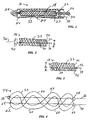
- stent 18 is shown in its nominal or relaxed state, indicating the absence of an external force.
- Stent 18 includes a framework or latticework 33 of resilient monofilament structural strands 34.
- the strands are arranged in two sets of parallel helices wound in opposite directions about a common longitudinal axis 36.
- the strands intersect one another to define a braid angle alpha ( ⁇ ) bisected by the longitudinal axis.
- the braid angle is in the range of about 60-150°, more preferably about 90-140°.
- the braid angle is defined with reference to the relaxed state of the latticework. Compression of the stent into the delivery state substantially reduces the braid angle. At the same time, the braid angle influences the relationship between radial compression and axial elongation of the stent. Smaller braid angles result in less axial shortening for a given amount of radial enlargement. Conversely, with a larger braid angle, the same radial expansion results in more axial shortening. For a given strand size and strength, a larger braid angle imparts greater resistance to radial compression and more positive acute fixation.
- Structural strands 34 are elastic, strong, biocompatible, hemocompatible, and resistant to corrosion and fatigue. Suitable materials include certain stainless spring steels, cobalt-based alloys, titanium alloys, and clad composites as disclosed in U.S. Patent No. 5,628,787. Several preferred cobalt-based alloys are sold under the brand names Elgiloy, Phynox, and MP35N.
- the strands also can be formed of polymers, including PET, polypropylene, PEEK, high density polyethylene, polysulfone, acetyl, PTFE, FEP, and polyurethane. Suitable strand diameters are about 0.002-0.015 inches (.05-.38 mm).
- Stent 18 also includes a control filament 38, coupled to the latticework at the proximal and distal ends of the latticework and extending proximally beyond the latticework.
- Control filament 38 preferably of monofilament construction, can be formed of the same materials used to form the latticework. Further, in certain applications it may be desired to provide a control filament having a modulus of elasticity much higher than the elastic modulus of the latticework material, even to the point that the control filament is considered inextensible rather than resilient.
- control filament materials can range beyond those suitable for the structural strands, although both must be strong, biocompatible, hemocompatible, and resistant to corrosion and fatigue.
- Control filament 38 is coupled to the latticework at two points spaced apart axially from one another: a distal end coupling 40 and a proximal end coupling 42.
- the distal end coupling is fixed, i.e., the distal end of the control filament is integral with the distal end of the latticework.
- distal coupling 40 is conveniently formed by thermal bonding. Specifically, the thermal bend is a weld as shown in Figure 2 for metal strands. Alternatively, a fusion bond can be formed when all of the strands are polymeric.
- Proximal end coupling 42 accommodates axial movement of the control filament relative to the latticework.
- proximal coupling 42 is a loop formed in one of the structural strands, with the control strand extending through the loop.
- stent 18 further incorporates a control feature that allows the user to set the axial position of control filament 38 relative to latticework 33. More particularly, this feature is a crimp 46 formed along the metal control filament proximally of loop 43. The crimp is formed after stent 18 is placed at the fixation site and allowed to radially expand into contact with surrounding tissue, and further after at least a slight additional axial shortening/radial expansion of the stent, so that the latticework bears against crimp 46 and maintains control filament 38 in tension. Increasing such further axial shortening increases the amount of tensile force along control filament 38, in turn increasing the tendency in stent 18 to resist radial compression.
- control filament 38 provides a tensile force that maintains the latticework at a larger diameter D 2 than the relaxed-state diameter D 1 shown in Figure 2.
- Figure 4 schematically illustrates an alternative stent 48 with a latticework 50 of interwoven helically wound structural strands.
- the latticework includes multiple strands, only a few of the strands are illustrated: a pair of strands 52 and 54 coupled to one another by a distal end connector 56 and a proximal end connector 58; and a substantially longer strand 60 having a distal end fold or loop 62, with its ends coupled by a proximal end connector 64.
- the connectors are located at the intersections of oppositely directed structural strands.
- Distal end connector 56 integrally couples the distal ends of structural strands 52 and 54, and the distal end of a control strand 66.
- a weld 68 integrally secures the distal end of a second control strand 70 to structural strand 60 along loop 62. While connector 56 and weld 68 are shown on the same device for convenience of illustration, a device typically would incorporate either one approach or the other. In either event, at the device distal end, the control strands are prevented from moving axially relative to the structural strands.
- distal connector 56 has openings for receiving the distal ends of the strands, in each case providing a substantially tight fit for a frictional hold on the associated strand end.
- the tight fit can be achieved, for example, using a shrink-fit polymer.
- an adhesive can secure each strand end.
- proximal end connector 58 has openings to receive the proximal ends of structural strands 52 and 54 in a tight or integral coupling as just described.
- an axial opening 72 through the connector is sufficiently large to allow the connector to the slide along control strand 66.
- control strand 66 does not slide freely, but only in response to the application of an external force.
- connector 58 incorporates a self-locking feature that facilitates setting a desired axial distance between the proximal and distal connectors, or between the proximal connector and a weld or other coupling, without the need for a crimp in the control strand.
- opening 72 can allow free sliding of the control strand, with a more tightly mounted locking sleeve 75 positionable to set the axial distance between connectors.
- stent 48 may be provided with multiple control strands distributed evenly about its circumference, or may require only a single control strand.
- Connectors 56 and 58 in addition to securing the control strands, also selvege the proximal and distal ends of the latticework to eliminate what otherwise would be exposed ends of the metal structural strands. When just a few control strands are required, additional connectors can be provided solely for joining the free ends of structural strands.
- Figure 7 schematically illustrates a pair of structural strands 76 of an alternative embodiment stent 78, coupled at their distal ends by a distal end connector 80, and at their proximal ends by a proximal connector 82.
- An axial control member 84 is integrally received within distal connector 80 and slides within proximal connector 82.
- control member 84 is formed with a larger diameter than its counterparts, and thus is sufficiently stiff in the axial direction to axially elongate (and radially contract) stent 78 from its relaxed state, by a sliding of the proximal connector proximally along the control member.
- FIGs 8 and 9 schematically illustrate, in part, the deployment of a stent 86 within a blood vessel 88 at a fixation location along a vessel wall 90.
- deployment proceeds in a manner that is known and not particularly germane to the present invention. More particularly, device 16 or another suitable device is advanced translumenally to an appropriate alignment near the fixation site, then manipulated to release stent 86, allowing its radial expansion into contact with tissue wall 90 as shown.
- An axially extending control filament 92 is coupled integrally at a distal coupling 94, and slides relative to the stent at a proximal coupling 96.
- a crimp can be formed in control filament 92 as in figure 3, or a self-locking connector as in figure 6 can be left in the position shown.
- a tensile force from the control filament augments the elastic restoring force in the coiled structural strands, to more effectively resist radial contraction of the vessel.
- a further advantage of the invention is realized by locking the stent proximal end along the control strand as shown in Figure 9, i.e. distally of the location shown in Figure 8. This increases the stent's resistance to radial contraction, first by increasing tension along the control filament, and second by axially shortening and radially enlarging the latticework to increase the braid angle.
- This latter feature is particularly beneficial in the event that the fixation site along vessel 88 is larger in diameter than anticipated, leading to deployment of a stent having less than the most preferred diameter.
- a stent without a control member i.e. relying solely on the restoring force within the structural strands, may not provide a restoring force sufficient for acute fixation or resistance to contraction. Retrieval of the stent and deployment of a larger size stent may be required.
- stent 86 can be reliably secured and offer sufficient resistance to vessel constriction, even if the vessel size is larger than anticipated before deployment.
- the proximal end of stent 86 simply is moved distally to a greater degree than previously thought necessary and fixed by a crimp or a self-locking connector, further radially enlarging the stent to provide sufficient fixation and resistance to contraction.
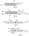
- Figure 10 illustrates a further alternative embodiment stent 100 with interbraided helical structural strands, in which a control member 102 is formed from a single strand, folded or doubled over upon itself to form a looped end 104 for the distal coupling.
- the doubled strand is placed through a loop 106 at the proximal end of the latticework.
- a further alternative stent 108 is formed of a latticework including oppositely directed interwoven helical structural strands 110.
- Stent 108 also incorporates a control member 112 that is doubled or looped as in Figure 10.
- free ends 114 and 116 of the doubled control member are welded or otherwise integrally secured to a distal end of the latticework, and the control member is retained slidably in proximal end loops or clamps at 118 and 120.
- the proximal, looped end 122 of the control member can be pulled while the proximal end of stent 108 is held stationary, to axially shorten and radially enlarge the stent.
- Figures 12 and 13 illustrate another alternative embodiment stent 124 formed by interbraided oppositely directed helical structural strands.
- a control strand 126 is integrally secured to the distal end of stent 124 by a connector 125. Further, control strand 126 is slidably coupled to the latticework through a connector 128 similar to connector 58 and Figure 6, positioned medially along the stent rather than at its proximal end. In this arrangement, control strand 126 can be manipulated to selectively axially shorten and radially expand only a distal region of the stent, i.e. the region between connectors 125 and 128. Figure 13 illustrates the result of selectively locking the control strand to provide a larger distal radius.
- Figure 14 illustrates a stent 130 in which a control strand 132 is fixed at 134 along a medial region of the stent, and slidably secured at 136 to the proximal end of the stent, thus to selectively radially enlarge only a proximal region.
- further control strands can be provided to enlarge further selected regions along the stent length, affording considerable flexibility in the stent's radius profile (i.e. the variance in stent radii over the stent length) to conform to body lumen irregularities.
- Figures 15 and 16 illustrate a further alternative embodiment stent 138 including a latticework of interbraided helical strands, and several control members 140 formed of a recovery metal, for example, a titanium-nickel alloy sold under the name "Nitinol.”
- the recovery metal members are plastically deformable away from a nominal shape, so long as they remain below a predetermined threshold temperature. When heated to the threshold or above, the metal members assume the nominal shape.
- control members 140 are shown in the nominal shape: a crimped, axially shortened, somewhat sinusoidal configuration. Each of the control members is integrally secured, at its proximal and distal ends, to the proximal and distal ends of latticework 142, respectively. Accordingly, the latticework axially expands and contracts along with the control members.
- control members 140 are shown plastically deformed to an elongated, linear state, axially elongating and radially reducing the latticework to facilitate intraluminal delivery of the stent. Once deployed, control members 140 are heated at least to the threshold temperature, whereupon they return to the shortened state illustrated in Figure 15, thus to axially shorten and radially enlarge the stent.
- this approach affords more control over the degree of radial expansion imparted by the control members. Radial enlargement is accomplished without physical manipulation of the stent, requiring only heating of the control members. This version, however, lacks the capability of adjusting the axial setting of the stent along the control member or members, to selectively vary the degree of radial enlargement.
- the inclined, broken line 144 plots the restoring force due to the structural strands alone.
- a broken line 146 similarly plots the restoring force due to the control member alone.
- a solid line 148 is the resultant restoring force of the structural strands and control member combined. To the left of the vertical axis, the resultant force and structural strand force coincide, indicating a slack control member that contributes no restoring force. To the right of this axis, the resultant restoring force represents the combined effect of increased tension in the control member and increased bending stress in the coiled structural strands as the coil radii become smaller.
- the chart in Figure 18 represents a stent with balanced, non-zero restoring forces in the nominal state. More particularly, an axial control strand is in tension, exerting a restoring force tending to axially shorten the stent. At the same time the helical structural strands exert a radial force, due to bending, tending to radially reduce/axially elongate the stent. Linear plots of the force of the structural strands and the force of the control strand are shown at 150 and 152, respectively. The resultant force is indicated by a solid line 154. Again, a coincidence of the resultant line and the structural strand force line indicates slack in the control strand, beginning at a pre-determined axial length less than the nominal length.
- the chart in Figure 19 represents a stent configuration in which the nominal, relaxed state is controlled solely by the structural strands, because of slack in the axial control strand.
- the structural strand force and control strand force are represented separately at 156 and 158, and their combined effect is shown by a solid line 160.
- a salient advantage of this configuration is that a stent can be designed to exert a gentle pressure against the surrounding tissue in a vessel slightly smaller than the nominal radius, yet also can exert considerably increased resistance when a muscular contraction or other event threatens to severely constrict the vessel.
- the respective plots of control member restoring force can represent a combined force of several control members acting in concert. Further, if the control members involved were instead the larger-diameter type with substantial axial rigidity as shown in Figure 7, the plots of structural strand force and resultant force would not coincide at larger radii as shown. Rather, at such radii the control members, under compression, would tend to resist further radial enlargement.
- axial control members are coupled to tubular self-expanding prostheses to control the degree and nature of their radial expansion.
- Control members of substantially inextensible materials or recovery metals can be used to set definite limits on radial expansion.
- more resilient control members are used to augment the restoring force provided by the helically wound structural strands of the stent. The coupling of control strands at intermediate locations along the stent facilitates selective radial expansions to accommodate body lumen irregularities.
Landscapes
- Health & Medical Sciences (AREA)
- Engineering & Computer Science (AREA)
- Biomedical Technology (AREA)
- Cardiology (AREA)
- Oral & Maxillofacial Surgery (AREA)
- Transplantation (AREA)
- Heart & Thoracic Surgery (AREA)
- Vascular Medicine (AREA)
- Life Sciences & Earth Sciences (AREA)
- Animal Behavior & Ethology (AREA)
- General Health & Medical Sciences (AREA)
- Public Health (AREA)
- Veterinary Medicine (AREA)
- Prostheses (AREA)
- Media Introduction/Drainage Providing Device (AREA)
Applications Claiming Priority (2)
| Application Number | Priority Date | Filing Date | Title |
|---|---|---|---|
| US5523897P | 1997-08-12 | 1997-08-12 | |
| US55238P | 1997-08-12 |
Publications (2)
| Publication Number | Publication Date |
|---|---|
| EP0897699A2 true EP0897699A2 (fr) | 1999-02-24 |
| EP0897699A3 EP0897699A3 (fr) | 1999-12-01 |
Family
ID=21996590
Family Applications (1)
| Application Number | Title | Priority Date | Filing Date |
|---|---|---|---|
| EP98202120A Withdrawn EP0897699A3 (fr) | 1997-08-12 | 1998-06-25 | Prothése dilatable radialement avec contrÔle axial du diamètre |
Country Status (3)
| Country | Link |
|---|---|
| US (1) | US5984957A (fr) |
| EP (1) | EP0897699A3 (fr) |
| JP (1) | JPH1176420A (fr) |
Cited By (10)
| Publication number | Priority date | Publication date | Assignee | Title |
|---|---|---|---|---|
| WO2009102441A1 (fr) * | 2008-02-11 | 2009-08-20 | William A. Cook Australia Pty. Ltd. | Appareil de formation de courbe et greffe endovasculaire incurvable |
| WO2009126227A2 (fr) | 2008-04-09 | 2009-10-15 | William Cook Europe Aps | Endoprothèse vasculaire, appareil et procédé d’adaptation |
| US7704276B2 (en) * | 2002-11-15 | 2010-04-27 | Synecor, Llc | Endoprostheses and methods of manufacture |
| CN102573709A (zh) * | 2009-07-15 | 2012-07-11 | 戈尔企业控股股份有限公司 | 具有反颈缩性质的管子 |
| JP2017153596A (ja) * | 2016-02-29 | 2017-09-07 | 株式会社ジェイ・エム・エス | ステント |
| WO2017157081A1 (fr) * | 2016-03-15 | 2017-09-21 | 北京奇伦天佑创业投资有限公司 | Endoprothèse recouverte dotée de ramifications et son système d'implantation |
| EP3189816A4 (fr) * | 2014-09-01 | 2018-04-11 | JMS Co., Ltd. | Endoprothèse en résine synthétique |
| EP3406227A4 (fr) * | 2016-01-19 | 2019-02-27 | JMS Co., Ltd. | Stent en résine synthétique |
| US20200229955A1 (en) * | 2017-11-06 | 2020-07-23 | Ea Pharma Co., Ltd. | Stent and medical device comprising same |
| US11559384B2 (en) | 2018-06-05 | 2023-01-24 | Boston Scientific Scimed, Inc. | Stent with selectively curved region |
Families Citing this family (275)
| Publication number | Priority date | Publication date | Assignee | Title |
|---|---|---|---|---|
| US6006134A (en) | 1998-04-30 | 1999-12-21 | Medtronic, Inc. | Method and device for electronically controlling the beating of a heart using venous electrical stimulation of nerve fibers |
| US6015432A (en) * | 1998-02-25 | 2000-01-18 | Cordis Corporation | Wire reinforced vascular prosthesis |
| US20040254635A1 (en) | 1998-03-30 | 2004-12-16 | Shanley John F. | Expandable medical device for delivery of beneficial agent |
| US6241762B1 (en) | 1998-03-30 | 2001-06-05 | Conor Medsystems, Inc. | Expandable medical device with ductile hinges |
| US7208010B2 (en) | 2000-10-16 | 2007-04-24 | Conor Medsystems, Inc. | Expandable medical device for delivery of beneficial agent |
| US6293967B1 (en) | 1998-10-29 | 2001-09-25 | Conor Medsystems, Inc. | Expandable medical device with ductile hinges |
| US6905743B1 (en) * | 1999-02-25 | 2005-06-14 | Boston Scientific Scimed, Inc. | Dimensionally stable balloons |
| US6445958B1 (en) | 1999-04-15 | 2002-09-03 | Intermedics, Inc. | Steerable coronary sinus defibrillation lead |
| US8016877B2 (en) | 1999-11-17 | 2011-09-13 | Medtronic Corevalve Llc | Prosthetic valve for transluminal delivery |
| US7018406B2 (en) | 1999-11-17 | 2006-03-28 | Corevalve Sa | Prosthetic valve for transluminal delivery |
| US8579966B2 (en) | 1999-11-17 | 2013-11-12 | Medtronic Corevalve Llc | Prosthetic valve for transluminal delivery |
| US6547761B2 (en) * | 2000-01-07 | 2003-04-15 | Scimed Life Systems, Inc. | Drainage catheter |
| US8241274B2 (en) | 2000-01-19 | 2012-08-14 | Medtronic, Inc. | Method for guiding a medical device |
| US7749245B2 (en) | 2000-01-27 | 2010-07-06 | Medtronic, Inc. | Cardiac valve procedure methods and devices |
| WO2002005888A1 (fr) | 2000-06-30 | 2002-01-24 | Viacor Incorporated | Filtre intravasculaire avec mecanisme de piegeage de debris |
| JP2004506469A (ja) | 2000-08-18 | 2004-03-04 | アトリテック, インコーポレイテッド | 心耳からの血流をろ過するための拡張可能な埋め込みデバイス |
| US20020028712A1 (en) * | 2000-08-18 | 2002-03-07 | Sportstec, Inc. | Apparatuses and methods for playing a golf-type game |
| EP1935380B1 (fr) | 2000-10-16 | 2010-05-12 | Conor Medsystems, Inc. | Dispositif médical extensible destiné à l'apport d'un agent utile |
| US6764507B2 (en) | 2000-10-16 | 2004-07-20 | Conor Medsystems, Inc. | Expandable medical device with improved spatial distribution |
| US20040088037A1 (en) * | 2000-12-27 | 2004-05-06 | American Medical Systems, Inc. | Method and apparatus for making a braided stent with spherically ended wires |
| US20040073294A1 (en) | 2002-09-20 | 2004-04-15 | Conor Medsystems, Inc. | Method and apparatus for loading a beneficial agent into an expandable medical device |
| EP1258230A3 (fr) | 2001-03-29 | 2003-12-10 | CardioSafe Ltd | Dispositif de cathéter à ballon |
| US6821291B2 (en) | 2001-06-01 | 2004-11-23 | Ams Research Corporation | Retrievable stent and method of use thereof |
| US6926732B2 (en) | 2001-06-01 | 2005-08-09 | Ams Research Corporation | Stent delivery device and method |
| US7674245B2 (en) | 2001-06-07 | 2010-03-09 | Cardiac Pacemakers, Inc. | Method and apparatus for an adjustable shape guide catheter |
| US8623077B2 (en) | 2001-06-29 | 2014-01-07 | Medtronic, Inc. | Apparatus for replacing a cardiac valve |
| US8771302B2 (en) | 2001-06-29 | 2014-07-08 | Medtronic, Inc. | Method and apparatus for resecting and replacing an aortic valve |
| US7544206B2 (en) | 2001-06-29 | 2009-06-09 | Medtronic, Inc. | Method and apparatus for resecting and replacing an aortic valve |
| FR2826863B1 (fr) | 2001-07-04 | 2003-09-26 | Jacques Seguin | Ensemble permettant la mise en place d'une valve prothetique dans un conduit corporel |
| FR2828091B1 (fr) | 2001-07-31 | 2003-11-21 | Seguin Jacques | Ensemble permettant la mise en place d'une valve prothetique dans un conduit corporel |
| JP4822626B2 (ja) * | 2001-07-31 | 2011-11-24 | マニー株式会社 | シャント挿入具 |
| US7097659B2 (en) | 2001-09-07 | 2006-08-29 | Medtronic, Inc. | Fixation band for affixing a prosthetic heart valve to tissue |
| GB0121980D0 (en) | 2001-09-11 | 2001-10-31 | Cathnet Science Holding As | Expandable stent |
| US7351255B2 (en) | 2001-12-03 | 2008-04-01 | Xtent, Inc. | Stent delivery apparatus and method |
| US7270668B2 (en) | 2001-12-03 | 2007-09-18 | Xtent, Inc. | Apparatus and methods for delivering coiled prostheses |
| US7892273B2 (en) | 2001-12-03 | 2011-02-22 | Xtent, Inc. | Custom length stent apparatus |
| US20040186551A1 (en) | 2003-01-17 | 2004-09-23 | Xtent, Inc. | Multiple independent nested stent structures and methods for their preparation and deployment |
| US20030135266A1 (en) | 2001-12-03 | 2003-07-17 | Xtent, Inc. | Apparatus and methods for delivery of multiple distributed stents |
| US8080048B2 (en) | 2001-12-03 | 2011-12-20 | Xtent, Inc. | Stent delivery for bifurcated vessels |
| US7309350B2 (en) | 2001-12-03 | 2007-12-18 | Xtent, Inc. | Apparatus and methods for deployment of vascular prostheses |
| US7294146B2 (en) | 2001-12-03 | 2007-11-13 | Xtent, Inc. | Apparatus and methods for delivery of variable length stents |
| US7137993B2 (en) | 2001-12-03 | 2006-11-21 | Xtent, Inc. | Apparatus and methods for delivery of multiple distributed stents |
| US7147656B2 (en) | 2001-12-03 | 2006-12-12 | Xtent, Inc. | Apparatus and methods for delivery of braided prostheses |
| US7182779B2 (en) | 2001-12-03 | 2007-02-27 | Xtent, Inc. | Apparatus and methods for positioning prostheses for deployment from a catheter |
| US6755812B2 (en) * | 2001-12-11 | 2004-06-29 | Cardiac Pacemakers, Inc. | Deflectable telescoping guide catheter |
| US7717899B2 (en) * | 2002-01-28 | 2010-05-18 | Cardiac Pacemakers, Inc. | Inner and outer telescoping catheter delivery system |
| US20030145122A1 (en) * | 2002-01-30 | 2003-07-31 | International Business Machines Corporation | Apparatus and method of allowing multiple partitions of a partitioned computer system to use a single network adapter |
| US8721713B2 (en) | 2002-04-23 | 2014-05-13 | Medtronic, Inc. | System for implanting a replacement valve |
| US6932829B2 (en) * | 2002-06-24 | 2005-08-23 | Cordis Corporation | Centering catheter |
| CA2495155A1 (fr) | 2002-08-15 | 2004-02-26 | Gmp Cardiac Care, Inc. | Endoprothese-greffon a rails |
| US6887266B2 (en) * | 2002-11-14 | 2005-05-03 | Synecor, Llc | Endoprostheses and methods of manufacture |
| US7285287B2 (en) | 2002-11-14 | 2007-10-23 | Synecor, Llc | Carbon dioxide-assisted methods of providing biocompatible intraluminal prostheses |
| WO2004045450A2 (fr) * | 2002-11-15 | 2004-06-03 | Synecor, Llc | Endoprotheses ameliorees et procedes de fabrication |
| EP1560548A2 (fr) * | 2002-11-15 | 2005-08-10 | GMP Cardiac Care, Inc. | Endoprothese a rail pour la reparation d'un anevrisme de l'aorte abdominale |
| US6932930B2 (en) | 2003-03-10 | 2005-08-23 | Synecor, Llc | Intraluminal prostheses having polymeric material with selectively modified crystallinity and methods of making same |
| EP2272544A1 (fr) | 2003-03-28 | 2011-01-12 | Conor Medsystems, Inc. | Dispositif médicinal implantable ayant un gradient de concentration de substance active |
| US7241308B2 (en) | 2003-06-09 | 2007-07-10 | Xtent, Inc. | Stent deployment systems and methods |
| US7785653B2 (en) | 2003-09-22 | 2010-08-31 | Innovational Holdings Llc | Method and apparatus for loading a beneficial agent into an expandable medical device |
| US9579194B2 (en) | 2003-10-06 | 2017-02-28 | Medtronic ATS Medical, Inc. | Anchoring structure with concave landing zone |
| US7553324B2 (en) | 2003-10-14 | 2009-06-30 | Xtent, Inc. | Fixed stent delivery devices and methods |
| CA2484906C (fr) * | 2003-10-17 | 2012-12-04 | Tyco Healthcare Group Lp | Dispositif d'acces chirurgical et fabrication connexe |
| US7186265B2 (en) | 2003-12-10 | 2007-03-06 | Medtronic, Inc. | Prosthetic cardiac valves and systems and methods for implanting thereof |
| US8287584B2 (en) | 2005-11-14 | 2012-10-16 | Sadra Medical, Inc. | Medical implant deployment tool |
| US7824442B2 (en) | 2003-12-23 | 2010-11-02 | Sadra Medical, Inc. | Methods and apparatus for endovascularly replacing a heart valve |
| US20120041550A1 (en) | 2003-12-23 | 2012-02-16 | Sadra Medical, Inc. | Methods and Apparatus for Endovascular Heart Valve Replacement Comprising Tissue Grasping Elements |
| US20050137694A1 (en) | 2003-12-23 | 2005-06-23 | Haug Ulrich R. | Methods and apparatus for endovascularly replacing a patient's heart valve |
| US9005273B2 (en) | 2003-12-23 | 2015-04-14 | Sadra Medical, Inc. | Assessing the location and performance of replacement heart valves |
| US8182528B2 (en) | 2003-12-23 | 2012-05-22 | Sadra Medical, Inc. | Locking heart valve anchor |
| US7959666B2 (en) | 2003-12-23 | 2011-06-14 | Sadra Medical, Inc. | Methods and apparatus for endovascularly replacing a heart valve |
| US8828078B2 (en) | 2003-12-23 | 2014-09-09 | Sadra Medical, Inc. | Methods and apparatus for endovascular heart valve replacement comprising tissue grasping elements |
| EP2526898B1 (fr) | 2003-12-23 | 2013-04-17 | Sadra Medical, Inc. | Valvule cardiaque repositionnable |
| US20050137687A1 (en) | 2003-12-23 | 2005-06-23 | Sadra Medical | Heart valve anchor and method |
| US7748389B2 (en) | 2003-12-23 | 2010-07-06 | Sadra Medical, Inc. | Leaflet engagement elements and methods for use thereof |
| US7326236B2 (en) | 2003-12-23 | 2008-02-05 | Xtent, Inc. | Devices and methods for controlling and indicating the length of an interventional element |
| US8603160B2 (en) | 2003-12-23 | 2013-12-10 | Sadra Medical, Inc. | Method of using a retrievable heart valve anchor with a sheath |
| US7824443B2 (en) | 2003-12-23 | 2010-11-02 | Sadra Medical, Inc. | Medical implant delivery and deployment tool |
| US9526609B2 (en) | 2003-12-23 | 2016-12-27 | Boston Scientific Scimed, Inc. | Methods and apparatus for endovascularly replacing a patient's heart valve |
| US7329279B2 (en) | 2003-12-23 | 2008-02-12 | Sadra Medical, Inc. | Methods and apparatus for endovascularly replacing a patient's heart valve |
| US8579962B2 (en) | 2003-12-23 | 2013-11-12 | Sadra Medical, Inc. | Methods and apparatus for performing valvuloplasty |
| US11278398B2 (en) | 2003-12-23 | 2022-03-22 | Boston Scientific Scimed, Inc. | Methods and apparatus for endovascular heart valve replacement comprising tissue grasping elements |
| US7381219B2 (en) | 2003-12-23 | 2008-06-03 | Sadra Medical, Inc. | Low profile heart valve and delivery system |
| US7780725B2 (en) | 2004-06-16 | 2010-08-24 | Sadra Medical, Inc. | Everting heart valve |
| US7445631B2 (en) | 2003-12-23 | 2008-11-04 | Sadra Medical, Inc. | Methods and apparatus for endovascularly replacing a patient's heart valve |
| US8840663B2 (en) | 2003-12-23 | 2014-09-23 | Sadra Medical, Inc. | Repositionable heart valve method |
| US8343213B2 (en) | 2003-12-23 | 2013-01-01 | Sadra Medical, Inc. | Leaflet engagement elements and methods for use thereof |
| US9254213B2 (en) | 2004-01-09 | 2016-02-09 | Rubicon Medical, Inc. | Stent delivery device |
| ITTO20040135A1 (it) | 2004-03-03 | 2004-06-03 | Sorin Biomedica Cardio Spa | Protesi valvolare cardiaca |
| US7323006B2 (en) | 2004-03-30 | 2008-01-29 | Xtent, Inc. | Rapid exchange interventional devices and methods |
| AU2005234793B2 (en) | 2004-04-23 | 2012-01-19 | 3F Therapeutics, Inc. | Implantable prosthetic valve |
| US8623067B2 (en) | 2004-05-25 | 2014-01-07 | Covidien Lp | Methods and apparatus for luminal stenting |
| US8617234B2 (en) * | 2004-05-25 | 2013-12-31 | Covidien Lp | Flexible vascular occluding device |
| JP2008502378A (ja) | 2004-05-25 | 2008-01-31 | チェストナット メディカル テクノロジーズ インコーポレイテッド | フレキシブルな血管閉鎖デバイス |
| CA2758946C (fr) | 2004-05-25 | 2014-10-21 | Tyco Healthcare Group Lp | Implantation d'endoprotheses vasculaires pour l'anevrysme |
| US20050288766A1 (en) | 2004-06-28 | 2005-12-29 | Xtent, Inc. | Devices and methods for controlling expandable prostheses during deployment |
| US8317859B2 (en) | 2004-06-28 | 2012-11-27 | J.W. Medical Systems Ltd. | Devices and methods for controlling expandable prostheses during deployment |
| US20060052867A1 (en) | 2004-09-07 | 2006-03-09 | Medtronic, Inc | Replacement prosthetic heart valve, system and method of implant |
| WO2006034436A2 (fr) | 2004-09-21 | 2006-03-30 | Stout Medical Group, L.P. | Dispositif de support expansible et procede d'utilisation |
| US8562672B2 (en) | 2004-11-19 | 2013-10-22 | Medtronic, Inc. | Apparatus for treatment of cardiac valves and method of its manufacture |
| DE102005003632A1 (de) | 2005-01-20 | 2006-08-17 | Fraunhofer-Gesellschaft zur Förderung der angewandten Forschung e.V. | Katheter für die transvaskuläre Implantation von Herzklappenprothesen |
| ITTO20050074A1 (it) | 2005-02-10 | 2006-08-11 | Sorin Biomedica Cardio Srl | Protesi valvola cardiaca |
| US7402168B2 (en) | 2005-04-11 | 2008-07-22 | Xtent, Inc. | Custom-length stent delivery system with independently operable expansion elements |
| US7962208B2 (en) | 2005-04-25 | 2011-06-14 | Cardiac Pacemakers, Inc. | Method and apparatus for pacing during revascularization |
| WO2006116761A2 (fr) * | 2005-04-27 | 2006-11-02 | Stout Medical Group, L.P. | Dispositif support expansible et son procede d'utilisation |
| US7914569B2 (en) | 2005-05-13 | 2011-03-29 | Medtronics Corevalve Llc | Heart valve prosthesis and methods of manufacture and use |
| US7320702B2 (en) | 2005-06-08 | 2008-01-22 | Xtent, Inc. | Apparatus and methods for deployment of multiple custom-length prostheses (III) |
| US7938851B2 (en) | 2005-06-08 | 2011-05-10 | Xtent, Inc. | Devices and methods for operating and controlling interventional apparatus |
| WO2007009107A2 (fr) | 2005-07-14 | 2007-01-18 | Stout Medical Group, P.L. | Dispositif de support dilatable et sa methode d'utilisation |
| EP1920920B1 (fr) * | 2005-08-25 | 2013-12-04 | Toray Battery Separator Film Co., Ltd. | Membrane microporeuse à couches multiples en polyéthylène, séparateur de batterie l'utilisant et batterie |
| US7712606B2 (en) | 2005-09-13 | 2010-05-11 | Sadra Medical, Inc. | Two-part package for medical implant |
| US20070078510A1 (en) | 2005-09-26 | 2007-04-05 | Ryan Timothy R | Prosthetic cardiac and venous valves |
| US20070213813A1 (en) | 2005-12-22 | 2007-09-13 | Symetis Sa | Stent-valves for valve replacement and associated methods and systems for surgery |
| US9078781B2 (en) | 2006-01-11 | 2015-07-14 | Medtronic, Inc. | Sterile cover for compressible stents used in percutaneous device delivery systems |
| EP1986568B1 (fr) | 2006-02-03 | 2017-04-05 | Covidien LP | Procédés et dispositifs servant à rétablir la circulation sanguine dans un système vasculaire bloqué |
| WO2007097983A2 (fr) | 2006-02-14 | 2007-08-30 | Sadra Medical, Inc. | Systemes et procedes pour installer un implant medical |
| US8152833B2 (en) | 2006-02-22 | 2012-04-10 | Tyco Healthcare Group Lp | Embolic protection systems having radiopaque filter mesh |
| WO2007109621A2 (fr) | 2006-03-20 | 2007-09-27 | Xtent, Inc. | Appareil et procédés destinés à la mise en place de segments prothétiques reliés entre eux |
| US8075615B2 (en) | 2006-03-28 | 2011-12-13 | Medtronic, Inc. | Prosthetic cardiac valve formed from pericardium material and methods of making same |
| US7625403B2 (en) | 2006-04-04 | 2009-12-01 | Medtronic Vascular, Inc. | Valved conduit designed for subsequent catheter delivered valve therapy |
| US7524331B2 (en) | 2006-04-06 | 2009-04-28 | Medtronic Vascular, Inc. | Catheter delivered valve having a barrier to provide an enhanced seal |
| US7740655B2 (en) | 2006-04-06 | 2010-06-22 | Medtronic Vascular, Inc. | Reinforced surgical conduit for implantation of a stented valve therein |
| US7591848B2 (en) | 2006-04-06 | 2009-09-22 | Medtronic Vascular, Inc. | Riveted stent valve for percutaneous use |
| WO2007131002A2 (fr) | 2006-05-01 | 2007-11-15 | Stout Medical Group, L.P. | Dispositif de soutien expansible et méthode d'utilisation |
| US11304800B2 (en) | 2006-09-19 | 2022-04-19 | Medtronic Ventor Technologies Ltd. | Sinus-engaging valve fixation member |
| US8348995B2 (en) | 2006-09-19 | 2013-01-08 | Medtronic Ventor Technologies, Ltd. | Axial-force fixation member for valve |
| US8834564B2 (en) | 2006-09-19 | 2014-09-16 | Medtronic, Inc. | Sinus-engaging valve fixation member |
| WO2008047354A2 (fr) | 2006-10-16 | 2008-04-24 | Ventor Technologies Ltd. | Système d'administration transapicale avec dérivation de débordement ventriculo-artérielle |
| US9622888B2 (en) | 2006-11-16 | 2017-04-18 | W. L. Gore & Associates, Inc. | Stent having flexibly connected adjacent stent elements |
| AU2007329243B2 (en) | 2006-12-06 | 2014-04-03 | Medtronic CV Luxembourg S.a.r.l | System and method for transapical delivery of an annulus anchored self-expanding valve |
| US7871436B2 (en) | 2007-02-16 | 2011-01-18 | Medtronic, Inc. | Replacement prosthetic heart valves and methods of implantation |
| US20080199510A1 (en) | 2007-02-20 | 2008-08-21 | Xtent, Inc. | Thermo-mechanically controlled implants and methods of use |
| US8486132B2 (en) | 2007-03-22 | 2013-07-16 | J.W. Medical Systems Ltd. | Devices and methods for controlling expandable prostheses during deployment |
| US7896915B2 (en) | 2007-04-13 | 2011-03-01 | Jenavalve Technology, Inc. | Medical device for treating a heart valve insufficiency |
| FR2915087B1 (fr) | 2007-04-20 | 2021-11-26 | Corevalve Inc | Implant de traitement d'une valve cardiaque, en particulier d'une valve mitrale, materiel inculant cet implant et materiel de mise en place de cet implant. |
| CA2692962C (fr) * | 2007-07-27 | 2016-09-13 | Microvention, Inc. | Bobine detachable integrant une resistance a l'etirement |
| US8747458B2 (en) | 2007-08-20 | 2014-06-10 | Medtronic Ventor Technologies Ltd. | Stent loading tool and method for use thereof |
| US10856970B2 (en) | 2007-10-10 | 2020-12-08 | Medtronic Ventor Technologies Ltd. | Prosthetic heart valve for transfemoral delivery |
| US9848981B2 (en) | 2007-10-12 | 2017-12-26 | Mayo Foundation For Medical Education And Research | Expandable valve prosthesis with sealing mechanism |
| US8926688B2 (en) | 2008-01-11 | 2015-01-06 | W. L. Gore & Assoc. Inc. | Stent having adjacent elements connected by flexible webs |
| US8157852B2 (en) | 2008-01-24 | 2012-04-17 | Medtronic, Inc. | Delivery systems and methods of implantation for prosthetic heart valves |
| US9149358B2 (en) | 2008-01-24 | 2015-10-06 | Medtronic, Inc. | Delivery systems for prosthetic heart valves |
| DK2254514T3 (en) | 2008-01-24 | 2018-12-17 | Medtronic Inc | STENTS FOR HEART VALVE PROSTHESIS |
| US9089422B2 (en) | 2008-01-24 | 2015-07-28 | Medtronic, Inc. | Markers for prosthetic heart valves |
| EP2254513B1 (fr) | 2008-01-24 | 2015-10-28 | Medtronic, Inc. | Stents pour valvules cardiaques prothétiques |
| US9393115B2 (en) | 2008-01-24 | 2016-07-19 | Medtronic, Inc. | Delivery systems and methods of implantation for prosthetic heart valves |
| ES2903231T3 (es) | 2008-02-26 | 2022-03-31 | Jenavalve Tech Inc | Stent para el posicionamiento y anclaje de una prótesis valvular en un sitio de implantación en el corazón de un paciente |
| US9044318B2 (en) | 2008-02-26 | 2015-06-02 | Jenavalve Technology Gmbh | Stent for the positioning and anchoring of a valvular prosthesis |
| EP3915525A1 (fr) | 2008-02-28 | 2021-12-01 | Medtronic, Inc. | Systèmes de prothèse de valve cardiaque |
| US9101503B2 (en) | 2008-03-06 | 2015-08-11 | J.W. Medical Systems Ltd. | Apparatus having variable strut length and methods of use |
| US8313525B2 (en) | 2008-03-18 | 2012-11-20 | Medtronic Ventor Technologies, Ltd. | Valve suturing and implantation procedures |
| US8430927B2 (en) | 2008-04-08 | 2013-04-30 | Medtronic, Inc. | Multiple orifice implantable heart valve and methods of implantation |
| US8312825B2 (en) | 2008-04-23 | 2012-11-20 | Medtronic, Inc. | Methods and apparatuses for assembly of a pericardial prosthetic heart valve |
| US8696743B2 (en) | 2008-04-23 | 2014-04-15 | Medtronic, Inc. | Tissue attachment devices and methods for prosthetic heart valves |
| US8840661B2 (en) | 2008-05-16 | 2014-09-23 | Sorin Group Italia S.R.L. | Atraumatic prosthetic heart valve prosthesis |
| WO2010031060A1 (fr) | 2008-09-15 | 2010-03-18 | Medtronic Ventor Technologies Ltd. | Valvule cardiaque prosthétique ayant des identifiants pour faciliter le positionnement radiographique |
| US8721714B2 (en) | 2008-09-17 | 2014-05-13 | Medtronic Corevalve Llc | Delivery system for deployment of medical devices |
| JP5635515B2 (ja) | 2008-09-25 | 2014-12-03 | アドバンスド バイファケーション システムズ, インコーポレイテッド | 部分的圧着ステント |
| US11298252B2 (en) | 2008-09-25 | 2022-04-12 | Advanced Bifurcation Systems Inc. | Stent alignment during treatment of a bifurcation |
| US8821562B2 (en) | 2008-09-25 | 2014-09-02 | Advanced Bifurcation Systems, Inc. | Partially crimped stent |
| US12076258B2 (en) | 2008-09-25 | 2024-09-03 | Advanced Bifurcation Systems Inc. | Selective stent crimping |
| US8828071B2 (en) | 2008-09-25 | 2014-09-09 | Advanced Bifurcation Systems, Inc. | Methods and systems for ostial stenting of a bifurcation |
| EP2617388B2 (fr) | 2008-10-10 | 2019-11-06 | Boston Scientific Scimed, Inc. | Dispositifs médicaux et systèmes de délivrance destinés à délivrer des dispositifs médicaux |
| US8137398B2 (en) | 2008-10-13 | 2012-03-20 | Medtronic Ventor Technologies Ltd | Prosthetic valve having tapered tip when compressed for delivery |
| US8986361B2 (en) | 2008-10-17 | 2015-03-24 | Medtronic Corevalve, Inc. | Delivery system for deployment of medical devices |
| US20100211176A1 (en) | 2008-11-12 | 2010-08-19 | Stout Medical Group, L.P. | Fixation device and method |
| US9408708B2 (en) | 2008-11-12 | 2016-08-09 | Stout Medical Group, L.P. | Fixation device and method |
| EP2201911B1 (fr) | 2008-12-23 | 2015-09-30 | Sorin Group Italia S.r.l. | Valve prothétique extensible dotée d'appendices d'ancrage |
| WO2010102307A1 (fr) | 2009-03-06 | 2010-09-10 | Lazarus Effect, Inc. | Systèmes d'extraction et leur procédé d'utilisation |
| CN101856277B (zh) * | 2009-04-10 | 2012-02-01 | 王涛 | 一种可回收的单向活瓣覆膜支架 |
| EP2246011B1 (fr) | 2009-04-27 | 2014-09-03 | Sorin Group Italia S.r.l. | Conduit vasculaire prosthétique |
| CA3186201A1 (fr) | 2009-05-20 | 2010-11-25 | Lyra Therapeutics, Inc. | Dispositif medical autodeployable comportant des brins et des revetements polymeriques |
| US8992601B2 (en) | 2009-05-20 | 2015-03-31 | 480 Biomedical, Inc. | Medical implants |
| US8888840B2 (en) * | 2009-05-20 | 2014-11-18 | Boston Scientific Scimed, Inc. | Drug eluting medical implant |
| US9265633B2 (en) | 2009-05-20 | 2016-02-23 | 480 Biomedical, Inc. | Drug-eluting medical implants |
| US20110319987A1 (en) | 2009-05-20 | 2011-12-29 | Arsenal Medical | Medical implant |
| US9309347B2 (en) | 2009-05-20 | 2016-04-12 | Biomedical, Inc. | Bioresorbable thermoset polyester/urethane elastomers |
| US8372133B2 (en) | 2009-10-05 | 2013-02-12 | 480 Biomedical, Inc. | Polymeric implant delivery system |
| US8808369B2 (en) | 2009-10-05 | 2014-08-19 | Mayo Foundation For Medical Education And Research | Minimally invasive aortic valve replacement |
| US9226826B2 (en) | 2010-02-24 | 2016-01-05 | Medtronic, Inc. | Transcatheter valve structure and methods for valve delivery |
| CN103037815B (zh) | 2010-03-24 | 2015-05-13 | 高级分支系统股份有限公司 | 通过临时张开侧分支来处理分叉部的方法和系统 |
| AU2011232361B2 (en) | 2010-03-24 | 2015-05-28 | Advanced Bifurcation Systems Inc. | Stent alignment during treatment of a bifurcation |
| EP2549952A4 (fr) | 2010-03-24 | 2017-01-04 | Advanced Bifurcation Systems, Inc. | Système et procédé pour traiter une bifurcation |
| US8652204B2 (en) | 2010-04-01 | 2014-02-18 | Medtronic, Inc. | Transcatheter valve with torsion spring fixation and related systems and methods |
| US9326870B2 (en) * | 2010-04-23 | 2016-05-03 | Medtronic Vascular, Inc. | Biodegradable stent having non-biodegradable end portions and mechanisms for increased stent hoop strength |
| US8535380B2 (en) | 2010-05-13 | 2013-09-17 | Stout Medical Group, L.P. | Fixation device and method |
| IT1400327B1 (it) | 2010-05-21 | 2013-05-24 | Sorin Biomedica Cardio Srl | Dispositivo di supporto per protesi valvolari e corrispondente corredo. |
| JP2013526388A (ja) | 2010-05-25 | 2013-06-24 | イエナバルブ テクノロジー インク | 人工心臓弁、及び人工心臓弁とステントを備える経カテーテル搬送体内プロテーゼ |
| WO2012009675A2 (fr) | 2010-07-15 | 2012-01-19 | Lazarus Effect, Inc. | Système d'extraction et procédés d'utilisation associé |
| EP2608747A4 (fr) | 2010-08-24 | 2015-02-11 | Flexmedex Llc | Dispositif de soutien et procédé d'utilisation associé |
| EP2611388B1 (fr) | 2010-09-01 | 2022-04-27 | Medtronic Vascular Galway | Structure de support de valvule prothétique |
| CA2808673C (fr) | 2010-09-10 | 2019-07-02 | Symetis Sa | Dispositifs de remplacement de valve, dispositif d'acheminement pour dispositif de remplacement de valve et procede de fabrication d'un dispositif de remplacement de valve |
| WO2012037327A1 (fr) * | 2010-09-16 | 2012-03-22 | Mayo Foundation For Medical Education And Research | Stent à diamètre variable mécaniquement ajustable |
| US9149286B1 (en) | 2010-11-12 | 2015-10-06 | Flexmedex, LLC | Guidance tool and method for use |
| EP4424283A2 (fr) | 2011-02-08 | 2024-09-04 | Advanced Bifurcation Systems Inc. | Système et procédés de traitement d'une bifurcation à l'aide d'un stent entièrement serti |
| EP2672925B1 (fr) | 2011-02-08 | 2017-05-03 | Advanced Bifurcation Systems, Inc. | Appareil comprenant lusieurs endoprothèses et plusieurs ballonnets pour traiter des bifurcations |
| EP2486894B1 (fr) | 2011-02-14 | 2021-06-09 | Sorin Group Italia S.r.l. | Dispositif d'ancrage sans suture pour prothèses valvulaires cardiaques |
| EP2486893B1 (fr) | 2011-02-14 | 2017-07-05 | Sorin Group Italia S.r.l. | Dispositif d'ancrage sans suture pour prothèses valvulaires cardiaques |
| EP4119095A1 (fr) | 2011-03-21 | 2023-01-18 | Cephea Valve Technologies, Inc. | Appareil à soupape basé sur disque |
| EP2520251A1 (fr) | 2011-05-05 | 2012-11-07 | Symetis SA | Procédé et appareil pour compresser des valvules d'endoprothèse |
| WO2012162437A1 (fr) | 2011-05-23 | 2012-11-29 | Lazarus Effect, Inc. | Systèmes d'extraction et procédés pour l'utilisation de ceux-ci |
| EP2731550B1 (fr) | 2011-07-12 | 2016-02-24 | Boston Scientific Scimed, Inc. | Système de couplage pour une valvule de remplacement |
| US11026708B2 (en) | 2011-07-26 | 2021-06-08 | Thrombx Medical, Inc. | Intravascular thromboembolectomy device and method using the same |
| JP2014529445A (ja) | 2011-08-23 | 2014-11-13 | フレックスメデックス,エルエルシー | 組織除去装置及び方法 |
| US9131926B2 (en) | 2011-11-10 | 2015-09-15 | Boston Scientific Scimed, Inc. | Direct connect flush system |
| US8940014B2 (en) | 2011-11-15 | 2015-01-27 | Boston Scientific Scimed, Inc. | Bond between components of a medical device |
| US8951243B2 (en) | 2011-12-03 | 2015-02-10 | Boston Scientific Scimed, Inc. | Medical device handle |
| US9510945B2 (en) | 2011-12-20 | 2016-12-06 | Boston Scientific Scimed Inc. | Medical device handle |
| US9277993B2 (en) | 2011-12-20 | 2016-03-08 | Boston Scientific Scimed, Inc. | Medical device delivery systems |
| EP2842517A1 (fr) | 2011-12-29 | 2015-03-04 | Sorin Group Italia S.r.l. | Kit pour l'implantation de conduits vasculaires prosthétiques |
| WO2013112547A1 (fr) | 2012-01-25 | 2013-08-01 | Boston Scientific Scimed, Inc. | Ensemble de valvule avec un joint bioabsorbant et un implant de valvule remplaçable |
| US9883941B2 (en) | 2012-06-19 | 2018-02-06 | Boston Scientific Scimed, Inc. | Replacement heart valve |
| US9114001B2 (en) | 2012-10-30 | 2015-08-25 | Covidien Lp | Systems for attaining a predetermined porosity of a vascular device |
| US9452070B2 (en) | 2012-10-31 | 2016-09-27 | Covidien Lp | Methods and systems for increasing a density of a region of a vascular device |
| US9943427B2 (en) | 2012-11-06 | 2018-04-17 | Covidien Lp | Shaped occluding devices and methods of using the same |
| US9157174B2 (en) | 2013-02-05 | 2015-10-13 | Covidien Lp | Vascular device for aneurysm treatment and providing blood flow into a perforator vessel |
| JP6561044B2 (ja) | 2013-05-03 | 2019-08-14 | メドトロニック,インコーポレイテッド | 弁搬送ツール |
| US9561103B2 (en) | 2013-07-17 | 2017-02-07 | Cephea Valve Technologies, Inc. | System and method for cardiac valve repair and replacement |
| JP6563394B2 (ja) | 2013-08-30 | 2019-08-21 | イェーナヴァルヴ テクノロジー インコーポレイテッド | 人工弁のための径方向に折り畳み自在のフレーム及び当該フレームを製造するための方法 |
| ES2733317T3 (es) | 2014-03-04 | 2019-11-28 | Thrombx Medical Inc | Dispositivo de trombectomía intravascular que tiene una serie de elementos de aprehensión de coágulos |
| US9901445B2 (en) | 2014-11-21 | 2018-02-27 | Boston Scientific Scimed, Inc. | Valve locking mechanism |
| US10299948B2 (en) | 2014-11-26 | 2019-05-28 | W. L. Gore & Associates, Inc. | Balloon expandable endoprosthesis |
| EP4306080A3 (fr) | 2014-12-09 | 2024-04-10 | Cephea Valve Technologies, Inc. | Valvules cardiaques de remplacement et procédé de fabrication |
| US10449043B2 (en) | 2015-01-16 | 2019-10-22 | Boston Scientific Scimed, Inc. | Displacement based lock and release mechanism |
| US9861477B2 (en) | 2015-01-26 | 2018-01-09 | Boston Scientific Scimed Inc. | Prosthetic heart valve square leaflet-leaflet stitch |
| US9788942B2 (en) | 2015-02-03 | 2017-10-17 | Boston Scientific Scimed Inc. | Prosthetic heart valve having tubular seal |
| US10201417B2 (en) | 2015-02-03 | 2019-02-12 | Boston Scientific Scimed Inc. | Prosthetic heart valve having tubular seal |
| CN107405470A (zh) | 2015-02-11 | 2017-11-28 | 柯惠有限合伙公司 | 带可扩张尖端的医疗装置和方法 |
| US10285809B2 (en) | 2015-03-06 | 2019-05-14 | Boston Scientific Scimed Inc. | TAVI anchoring assist device |
| US10426617B2 (en) | 2015-03-06 | 2019-10-01 | Boston Scientific Scimed, Inc. | Low profile valve locking mechanism and commissure assembly |
| US10080652B2 (en) | 2015-03-13 | 2018-09-25 | Boston Scientific Scimed, Inc. | Prosthetic heart valve having an improved tubular seal |
| CN107530168B (zh) | 2015-05-01 | 2020-06-09 | 耶拿阀门科技股份有限公司 | 在心脏瓣膜替换中具有降低的起搏器比例的装置和方法 |
| EP3294220B1 (fr) | 2015-05-14 | 2023-12-06 | Cephea Valve Technologies, Inc. | Dispositifs et systèmes de mise en place de valve cardiaque |
| WO2016183526A1 (fr) | 2015-05-14 | 2016-11-17 | Cephea Valve Technologies, Inc. | Valvules mitrales de remplacement |
| US10195392B2 (en) | 2015-07-02 | 2019-02-05 | Boston Scientific Scimed, Inc. | Clip-on catheter |
| WO2017004377A1 (fr) | 2015-07-02 | 2017-01-05 | Boston Scientific Scimed, Inc. | Cône avant réglable |
| US10179041B2 (en) | 2015-08-12 | 2019-01-15 | Boston Scientific Scimed Icn. | Pinless release mechanism |
| US10136991B2 (en) | 2015-08-12 | 2018-11-27 | Boston Scientific Scimed Inc. | Replacement heart valve implant |
| US10779940B2 (en) | 2015-09-03 | 2020-09-22 | Boston Scientific Scimed, Inc. | Medical device handle |
| JP6597171B2 (ja) * | 2015-10-22 | 2019-10-30 | 株式会社ジェイ・エム・エス | ステントデリバリーシステム |
| US10342660B2 (en) | 2016-02-02 | 2019-07-09 | Boston Scientific Inc. | Tensioned sheathing aids |
| US10245136B2 (en) | 2016-05-13 | 2019-04-02 | Boston Scientific Scimed Inc. | Containment vessel with implant sheathing guide |
| US10583005B2 (en) | 2016-05-13 | 2020-03-10 | Boston Scientific Scimed, Inc. | Medical device handle |
| EP3454795B1 (fr) | 2016-05-13 | 2023-01-11 | JenaValve Technology, Inc. | Système d'implantation de prothèse de valve cardiaque pour la pose d'une prothèse de valve cardiaque avec une gaine d'introduction et système de chargement |
| US10201416B2 (en) | 2016-05-16 | 2019-02-12 | Boston Scientific Scimed, Inc. | Replacement heart valve implant with invertible leaflets |
| US10568752B2 (en) | 2016-05-25 | 2020-02-25 | W. L. Gore & Associates, Inc. | Controlled endoprosthesis balloon expansion |
| US11331187B2 (en) | 2016-06-17 | 2022-05-17 | Cephea Valve Technologies, Inc. | Cardiac valve delivery devices and systems |
| JP7114482B2 (ja) * | 2016-11-30 | 2022-08-08 | 株式会社ジェイ・エム・エス | ステント |
| EP4209196A1 (fr) | 2017-01-23 | 2023-07-12 | Cephea Valve Technologies, Inc. | Valvules mitrales de remplacement |
| CN110621260B (zh) | 2017-01-23 | 2022-11-25 | 科菲瓣膜技术有限公司 | 置换的二尖瓣 |
| JP7094965B2 (ja) | 2017-01-27 | 2022-07-04 | イエナバルブ テクノロジー インク | 心臓弁模倣 |
| JP6880976B2 (ja) * | 2017-04-19 | 2021-06-02 | 株式会社ジェイ・エム・エス | ステント |
| US10722257B2 (en) | 2017-05-12 | 2020-07-28 | Covidien Lp | Retrieval of material from vessel lumens |
| US10709464B2 (en) | 2017-05-12 | 2020-07-14 | Covidien Lp | Retrieval of material from vessel lumens |
| US11191555B2 (en) | 2017-05-12 | 2021-12-07 | Covidien Lp | Retrieval of material from vessel lumens |
| US11298145B2 (en) | 2017-05-12 | 2022-04-12 | Covidien Lp | Retrieval of material from vessel lumens |
| US11129630B2 (en) | 2017-05-12 | 2021-09-28 | Covidien Lp | Retrieval of material from vessel lumens |
| WO2018226915A1 (fr) | 2017-06-08 | 2018-12-13 | Boston Scientific Scimed, Inc. | Structure de support de commissure d'implant de valvule cardiaque |
| WO2018232044A1 (fr) | 2017-06-12 | 2018-12-20 | Covidien Lp | Outils de gainage pour dispositifs de traitement, ainsi que procédés et systèmes associés |
| US10478322B2 (en) | 2017-06-19 | 2019-11-19 | Covidien Lp | Retractor device for transforming a retrieval device from a deployed position to a delivery position |
| US10575864B2 (en) | 2017-06-22 | 2020-03-03 | Covidien Lp | Securing element for resheathing an intravascular device and associated systems and methods |
| US10898325B2 (en) | 2017-08-01 | 2021-01-26 | Boston Scientific Scimed, Inc. | Medical implant locking mechanism |
| WO2019035966A1 (fr) | 2017-08-16 | 2019-02-21 | Boston Scientific Scimed, Inc. | Ensemble commissure de valvule cardiaque de remplacement |
| CA3075398A1 (fr) | 2017-09-11 | 2019-03-14 | Thrombx Medical, Inc. | Dispositifs et methodes de thrombo-embolectomie intravasculaire |
| JP7047106B2 (ja) | 2018-01-19 | 2022-04-04 | ボストン サイエンティフィック サイムド,インコーポレイテッド | フィードバックループ付医療装置送達システム |
| JP7055882B2 (ja) | 2018-01-19 | 2022-04-18 | ボストン サイエンティフィック サイムド,インコーポレイテッド | トランスカテーテル弁システム用誘導モード留置センサ |
| EP3749252A1 (fr) | 2018-02-07 | 2020-12-16 | Boston Scientific Scimed, Inc. | Système de pose de dispositif médical avec élément d'alignement |
| US11065009B2 (en) | 2018-02-08 | 2021-07-20 | Covidien Lp | Vascular expandable devices |
| US11065136B2 (en) | 2018-02-08 | 2021-07-20 | Covidien Lp | Vascular expandable devices |
| EP3758651B1 (fr) | 2018-02-26 | 2022-12-07 | Boston Scientific Scimed, Inc. | Marqueur radio-opaque intégré dans un joint adaptatif |
| EP3793478A1 (fr) | 2018-05-15 | 2021-03-24 | Boston Scientific Scimed, Inc. | Ensemble commissure de valvule cardiaque de remplacement |
| CN112437649A (zh) | 2018-05-23 | 2021-03-02 | 索林集团意大利有限责任公司 | 心脏瓣膜假体 |
| WO2019236491A1 (fr) * | 2018-06-04 | 2019-12-12 | Boston Scientific Scimed, Inc. | Endoprothèse amovible |
| WO2019241477A1 (fr) | 2018-06-13 | 2019-12-19 | Boston Scientific Scimed, Inc. | Dispositif de pose de valvule cardiaque de remplacement |
| CN113164271A (zh) | 2018-09-24 | 2021-07-23 | 波士顿科学国际有限公司 | 可重新定位且可移除的支架 |
| WO2020123486A1 (fr) | 2018-12-10 | 2020-06-18 | Boston Scientific Scimed, Inc. | Système d'administration de dispositif médical comprenant un élément de résistance |
| US11439504B2 (en) | 2019-05-10 | 2022-09-13 | Boston Scientific Scimed, Inc. | Replacement heart valve with improved cusp washout and reduced loading |
Citations (3)
| Publication number | Priority date | Publication date | Assignee | Title |
|---|---|---|---|---|
| GB2189150A (en) * | 1986-04-21 | 1987-10-21 | Medinvent Sa | Prosthesis and process for its manufacture |
| US5015253A (en) * | 1989-06-15 | 1991-05-14 | Cordis Corporation | Non-woven endoprosthesis |
| US5064435A (en) * | 1990-06-28 | 1991-11-12 | Schneider (Usa) Inc. | Self-expanding prosthesis having stable axial length |
Family Cites Families (8)
| Publication number | Priority date | Publication date | Assignee | Title |
|---|---|---|---|---|
| US5507767A (en) * | 1992-01-15 | 1996-04-16 | Cook Incorporated | Spiral stent |
| US5549663A (en) * | 1994-03-09 | 1996-08-27 | Cordis Corporation | Endoprosthesis having graft member and exposed welded end junctions, method and procedure |
| US5765418A (en) * | 1994-05-16 | 1998-06-16 | Medtronic, Inc. | Method for making an implantable medical device from a refractory metal |
| JPH09215753A (ja) * | 1996-02-08 | 1997-08-19 | Schneider Usa Inc | チタン合金製自己拡張型ステント |
| US5891191A (en) * | 1996-04-30 | 1999-04-06 | Schneider (Usa) Inc | Cobalt-chromium-molybdenum alloy stent and stent-graft |
| US5817126A (en) * | 1997-03-17 | 1998-10-06 | Surface Genesis, Inc. | Compound stent |
| US5824054A (en) * | 1997-03-18 | 1998-10-20 | Endotex Interventional Systems, Inc. | Coiled sheet graft stent and methods of making and use |
| US5824053A (en) * | 1997-03-18 | 1998-10-20 | Endotex Interventional Systems, Inc. | Helical mesh endoprosthesis and methods of use |
-
1998
- 1998-05-15 US US09/079,806 patent/US5984957A/en not_active Expired - Lifetime
- 1998-06-25 EP EP98202120A patent/EP0897699A3/fr not_active Withdrawn
- 1998-07-15 JP JP20087998A patent/JPH1176420A/ja not_active Withdrawn
Patent Citations (3)
| Publication number | Priority date | Publication date | Assignee | Title |
|---|---|---|---|---|
| GB2189150A (en) * | 1986-04-21 | 1987-10-21 | Medinvent Sa | Prosthesis and process for its manufacture |
| US5015253A (en) * | 1989-06-15 | 1991-05-14 | Cordis Corporation | Non-woven endoprosthesis |
| US5064435A (en) * | 1990-06-28 | 1991-11-12 | Schneider (Usa) Inc. | Self-expanding prosthesis having stable axial length |
Cited By (15)
| Publication number | Priority date | Publication date | Assignee | Title |
|---|---|---|---|---|
| US7704276B2 (en) * | 2002-11-15 | 2010-04-27 | Synecor, Llc | Endoprostheses and methods of manufacture |
| WO2009102441A1 (fr) * | 2008-02-11 | 2009-08-20 | William A. Cook Australia Pty. Ltd. | Appareil de formation de courbe et greffe endovasculaire incurvable |
| US7976575B2 (en) | 2008-02-11 | 2011-07-12 | William A. Cook Australia Pty. Ltd. | Curve forming apparatus and curvable stent graft |
| WO2009126227A2 (fr) | 2008-04-09 | 2009-10-15 | William Cook Europe Aps | Endoprothèse vasculaire, appareil et procédé d’adaptation |
| WO2009126227A3 (fr) * | 2008-04-09 | 2009-12-10 | William Cook Europe Aps | Endoprothèse vasculaire, appareil et procédé d’adaptation |
| US8043356B2 (en) | 2008-04-09 | 2011-10-25 | Cook Medical Technologies Llc | Stent-graft and apparatus and fitting method |
| CN102573709A (zh) * | 2009-07-15 | 2012-07-11 | 戈尔企业控股股份有限公司 | 具有反颈缩性质的管子 |
| EP3189816A4 (fr) * | 2014-09-01 | 2018-04-11 | JMS Co., Ltd. | Endoprothèse en résine synthétique |
| US10265204B2 (en) | 2014-09-01 | 2019-04-23 | Jms Co., Ltd. | Synthetic resin stent |
| EP3406227A4 (fr) * | 2016-01-19 | 2019-02-27 | JMS Co., Ltd. | Stent en résine synthétique |
| US10744010B2 (en) | 2016-01-19 | 2020-08-18 | Jms Co., Ltd. | Synthetic resin stent |
| JP2017153596A (ja) * | 2016-02-29 | 2017-09-07 | 株式会社ジェイ・エム・エス | ステント |
| WO2017157081A1 (fr) * | 2016-03-15 | 2017-09-21 | 北京奇伦天佑创业投资有限公司 | Endoprothèse recouverte dotée de ramifications et son système d'implantation |
| US20200229955A1 (en) * | 2017-11-06 | 2020-07-23 | Ea Pharma Co., Ltd. | Stent and medical device comprising same |
| US11559384B2 (en) | 2018-06-05 | 2023-01-24 | Boston Scientific Scimed, Inc. | Stent with selectively curved region |
Also Published As
| Publication number | Publication date |
|---|---|
| EP0897699A3 (fr) | 1999-12-01 |
| US5984957A (en) | 1999-11-16 |
| JPH1176420A (ja) | 1999-03-23 |
Similar Documents
| Publication | Publication Date | Title |
|---|---|---|
| US5984957A (en) | Radially expanded prostheses with axial diameter control | |
| US10426643B2 (en) | Stents with attached looped ends | |
| EP0536164B1 (fr) | Prothese auto-expansive avec longueur axiale stable | |
| JP3280034B2 (ja) | よじれに抗するステント移植片 | |
| AU2008319288B2 (en) | Flexible stent graft | |
| US6635080B1 (en) | Prosthesis for repair of body passages | |
| EP0357003B2 (fr) | Endoprothèse expansible radialement | |
| CA2258732C (fr) | Reconstitution prothetique de conduits du corps humain | |
| CA2278128C (fr) | Extenseur vasculaire a extension autonome et de petite section | |
| EP0880949A1 (fr) | Stent-greffe avec bifurcation | |
| EP1477129A2 (fr) | Stent à greffer résistant au pliage | |
| JP2008149155A (ja) | ステントデバイス | |
| WO1999065419A1 (fr) | Prothese endovasculaire bifurquee a dilatation automatique | |
| WO1997021403A9 (fr) | Stent a greffer resistant aux plis | |
| JPH08299456A (ja) | フック付きの体内用人工装具を再捕捉する方法及び装置 |
Legal Events
| Date | Code | Title | Description |
|---|---|---|---|
| PUAI | Public reference made under article 153(3) epc to a published international application that has entered the european phase |
Free format text: ORIGINAL CODE: 0009012 |
|
| AK | Designated contracting states |
Kind code of ref document: A2 Designated state(s): AT BE CH CY DE DK ES FI FR GB GR IE IT LI LU MC NL PT SE |
|
| AX | Request for extension of the european patent |
Free format text: AL;LT;LV;MK;RO;SI |
|
| PUAL | Search report despatched |
Free format text: ORIGINAL CODE: 0009013 |
|
| RTI1 | Title (correction) |
Free format text: RADIALLY EXPANDABLE PROTHESIS WITH AXIAL DIAMETER CONTROL |
|
| AK | Designated contracting states |
Kind code of ref document: A3 Designated state(s): AT BE CH CY DE DK ES FI FR GB GR IE IT LI LU MC NL PT SE |
|
| AX | Request for extension of the european patent |
Free format text: AL;LT;LV;MK;RO;SI |
|
| 17P | Request for examination filed |
Effective date: 20000525 |
|
| AKX | Designation fees paid |
Free format text: DE FR GB IT |
|
| RBV | Designated contracting states (corrected) |
Designated state(s): AT BE CH CY DE DK ES FI FR GB GR IE IT LI LU MC NL PT SE |
|
| 17Q | First examination report despatched |
Effective date: 20030806 |
|
| STAA | Information on the status of an ep patent application or granted ep patent |
Free format text: STATUS: THE APPLICATION IS DEEMED TO BE WITHDRAWN |
|
| 18D | Application deemed to be withdrawn |
Effective date: 20031217 |